EP0365871B1 - Méthode de production d'un matériau pour joints et joint hautement compressible - Google Patents
Méthode de production d'un matériau pour joints et joint hautement compressible Download PDFInfo
- Publication number
- EP0365871B1 EP0365871B1 EP19890118272 EP89118272A EP0365871B1 EP 0365871 B1 EP0365871 B1 EP 0365871B1 EP 19890118272 EP19890118272 EP 19890118272 EP 89118272 A EP89118272 A EP 89118272A EP 0365871 B1 EP0365871 B1 EP 0365871B1
- Authority
- EP
- European Patent Office
- Prior art keywords
- sheets
- gasket
- forming
- thickness
- ptfe
- Prior art date
- Legal status (The legal status is an assumption and is not a legal conclusion. Google has not performed a legal analysis and makes no representation as to the accuracy of the status listed.)
- Expired - Lifetime
Links
- 239000000463 material Substances 0.000 title claims abstract description 56
- 238000000034 method Methods 0.000 title claims abstract description 16
- 229920001343 polytetrafluoroethylene Polymers 0.000 claims abstract description 50
- 239000011521 glass Substances 0.000 claims description 24
- 239000002131 composite material Substances 0.000 claims description 18
- 239000002245 particle Substances 0.000 claims description 15
- 239000011230 binding agent Substances 0.000 claims description 7
- 238000003490 calendering Methods 0.000 claims description 7
- -1 polytetrafluorethylene Polymers 0.000 claims description 6
- 239000007788 liquid Substances 0.000 claims description 4
- 238000002156 mixing Methods 0.000 claims description 3
- 238000001914 filtration Methods 0.000 claims description 2
- 238000005245 sintering Methods 0.000 claims description 2
- 238000011084 recovery Methods 0.000 abstract description 4
- 239000004810 polytetrafluoroethylene Substances 0.000 abstract 3
- 238000013023 gasketing Methods 0.000 description 32
- 239000000126 substance Substances 0.000 description 12
- 239000000945 filler Substances 0.000 description 8
- 239000000203 mixture Substances 0.000 description 6
- 230000015572 biosynthetic process Effects 0.000 description 5
- 239000010425 asbestos Substances 0.000 description 4
- 229910052895 riebeckite Inorganic materials 0.000 description 4
- 238000007789 sealing Methods 0.000 description 4
- 238000000926 separation method Methods 0.000 description 4
- 239000000853 adhesive Substances 0.000 description 3
- 230000001070 adhesive effect Effects 0.000 description 3
- 239000007799 cork Substances 0.000 description 3
- 230000006378 damage Effects 0.000 description 3
- 229920000295 expanded polytetrafluoroethylene Polymers 0.000 description 3
- 238000001125 extrusion Methods 0.000 description 3
- 238000011068 loading method Methods 0.000 description 3
- 239000000843 powder Substances 0.000 description 3
- 239000002904 solvent Substances 0.000 description 3
- VYPSYNLAJGMNEJ-UHFFFAOYSA-N Silicium dioxide Chemical compound O=[Si]=O VYPSYNLAJGMNEJ-UHFFFAOYSA-N 0.000 description 2
- 230000000712 assembly Effects 0.000 description 2
- 238000000429 assembly Methods 0.000 description 2
- 230000006835 compression Effects 0.000 description 2
- 238000007906 compression Methods 0.000 description 2
- 238000012669 compression test Methods 0.000 description 2
- 230000032798 delamination Effects 0.000 description 2
- 230000002045 lasting effect Effects 0.000 description 2
- 238000004519 manufacturing process Methods 0.000 description 2
- 241001330988 Palmyra Species 0.000 description 1
- 230000015556 catabolic process Effects 0.000 description 1
- 239000003518 caustics Substances 0.000 description 1
- 238000010276 construction Methods 0.000 description 1
- 238000011109 contamination Methods 0.000 description 1
- 238000006731 degradation reaction Methods 0.000 description 1
- 230000002708 enhancing effect Effects 0.000 description 1
- 230000007613 environmental effect Effects 0.000 description 1
- 239000012530 fluid Substances 0.000 description 1
- 230000005484 gravity Effects 0.000 description 1
- 238000010348 incorporation Methods 0.000 description 1
- 238000009434 installation Methods 0.000 description 1
- 230000014759 maintenance of location Effects 0.000 description 1
- 239000011159 matrix material Substances 0.000 description 1
- 230000000737 periodic effect Effects 0.000 description 1
- 239000000377 silicon dioxide Substances 0.000 description 1
Images
Classifications
-
- F—MECHANICAL ENGINEERING; LIGHTING; HEATING; WEAPONS; BLASTING
- F16—ENGINEERING ELEMENTS AND UNITS; GENERAL MEASURES FOR PRODUCING AND MAINTAINING EFFECTIVE FUNCTIONING OF MACHINES OR INSTALLATIONS; THERMAL INSULATION IN GENERAL
- F16J—PISTONS; CYLINDERS; SEALINGS
- F16J15/00—Sealings
- F16J15/02—Sealings between relatively-stationary surfaces
- F16J15/06—Sealings between relatively-stationary surfaces with solid packing compressed between sealing surfaces
- F16J15/10—Sealings between relatively-stationary surfaces with solid packing compressed between sealing surfaces with non-metallic packing
- F16J15/104—Sealings between relatively-stationary surfaces with solid packing compressed between sealing surfaces with non-metallic packing characterised by structure
-
- B—PERFORMING OPERATIONS; TRANSPORTING
- B29—WORKING OF PLASTICS; WORKING OF SUBSTANCES IN A PLASTIC STATE IN GENERAL
- B29C—SHAPING OR JOINING OF PLASTICS; SHAPING OF MATERIAL IN A PLASTIC STATE, NOT OTHERWISE PROVIDED FOR; AFTER-TREATMENT OF THE SHAPED PRODUCTS, e.g. REPAIRING
- B29C67/00—Shaping techniques not covered by groups B29C39/00 - B29C65/00, B29C70/00 or B29C73/00
- B29C67/02—Moulding by agglomerating
- B29C67/04—Sintering
-
- F—MECHANICAL ENGINEERING; LIGHTING; HEATING; WEAPONS; BLASTING
- F16—ENGINEERING ELEMENTS AND UNITS; GENERAL MEASURES FOR PRODUCING AND MAINTAINING EFFECTIVE FUNCTIONING OF MACHINES OR INSTALLATIONS; THERMAL INSULATION IN GENERAL
- F16L—PIPES; JOINTS OR FITTINGS FOR PIPES; SUPPORTS FOR PIPES, CABLES OR PROTECTIVE TUBING; MEANS FOR THERMAL INSULATION IN GENERAL
- F16L23/00—Flanged joints
- F16L23/16—Flanged joints characterised by the sealing means
- F16L23/18—Flanged joints characterised by the sealing means the sealing means being rings
-
- F—MECHANICAL ENGINEERING; LIGHTING; HEATING; WEAPONS; BLASTING
- F16—ENGINEERING ELEMENTS AND UNITS; GENERAL MEASURES FOR PRODUCING AND MAINTAINING EFFECTIVE FUNCTIONING OF MACHINES OR INSTALLATIONS; THERMAL INSULATION IN GENERAL
- F16L—PIPES; JOINTS OR FITTINGS FOR PIPES; SUPPORTS FOR PIPES, CABLES OR PROTECTIVE TUBING; MEANS FOR THERMAL INSULATION IN GENERAL
- F16L49/00—Connecting arrangements, e.g. joints, specially adapted for pipes of brittle material, e.g. glass, earthenware
- F16L49/04—Flanged joints
-
- Y—GENERAL TAGGING OF NEW TECHNOLOGICAL DEVELOPMENTS; GENERAL TAGGING OF CROSS-SECTIONAL TECHNOLOGIES SPANNING OVER SEVERAL SECTIONS OF THE IPC; TECHNICAL SUBJECTS COVERED BY FORMER USPC CROSS-REFERENCE ART COLLECTIONS [XRACs] AND DIGESTS
- Y10—TECHNICAL SUBJECTS COVERED BY FORMER USPC
- Y10S—TECHNICAL SUBJECTS COVERED BY FORMER USPC CROSS-REFERENCE ART COLLECTIONS [XRACs] AND DIGESTS
- Y10S277/00—Seal for a joint or juncture
- Y10S277/935—Seal made of a particular material
- Y10S277/936—Composite
- Y10S277/937—Glass particles or filament
-
- Y—GENERAL TAGGING OF NEW TECHNOLOGICAL DEVELOPMENTS; GENERAL TAGGING OF CROSS-SECTIONAL TECHNOLOGIES SPANNING OVER SEVERAL SECTIONS OF THE IPC; TECHNICAL SUBJECTS COVERED BY FORMER USPC CROSS-REFERENCE ART COLLECTIONS [XRACs] AND DIGESTS
- Y10—TECHNICAL SUBJECTS COVERED BY FORMER USPC
- Y10S—TECHNICAL SUBJECTS COVERED BY FORMER USPC CROSS-REFERENCE ART COLLECTIONS [XRACs] AND DIGESTS
- Y10S277/00—Seal for a joint or juncture
- Y10S277/935—Seal made of a particular material
- Y10S277/944—Elastomer or plastic
- Y10S277/945—Containing fluorine
- Y10S277/946—PTFE
-
- Y—GENERAL TAGGING OF NEW TECHNOLOGICAL DEVELOPMENTS; GENERAL TAGGING OF CROSS-SECTIONAL TECHNOLOGIES SPANNING OVER SEVERAL SECTIONS OF THE IPC; TECHNICAL SUBJECTS COVERED BY FORMER USPC CROSS-REFERENCE ART COLLECTIONS [XRACs] AND DIGESTS
- Y10—TECHNICAL SUBJECTS COVERED BY FORMER USPC
- Y10T—TECHNICAL SUBJECTS COVERED BY FORMER US CLASSIFICATION
- Y10T428/00—Stock material or miscellaneous articles
- Y10T428/25—Web or sheet containing structurally defined element or component and including a second component containing structurally defined particles
- Y10T428/252—Glass or ceramic [i.e., fired or glazed clay, cement, etc.] [porcelain, quartz, etc.]
-
- Y—GENERAL TAGGING OF NEW TECHNOLOGICAL DEVELOPMENTS; GENERAL TAGGING OF CROSS-SECTIONAL TECHNOLOGIES SPANNING OVER SEVERAL SECTIONS OF THE IPC; TECHNICAL SUBJECTS COVERED BY FORMER USPC CROSS-REFERENCE ART COLLECTIONS [XRACs] AND DIGESTS
- Y10—TECHNICAL SUBJECTS COVERED BY FORMER USPC
- Y10T—TECHNICAL SUBJECTS COVERED BY FORMER US CLASSIFICATION
- Y10T428/00—Stock material or miscellaneous articles
- Y10T428/31504—Composite [nonstructural laminate]
- Y10T428/3154—Of fluorinated addition polymer from unsaturated monomers
- Y10T428/31544—Addition polymer is perhalogenated
Definitions
- the present invention relates to a method for forming a gasket material including forming first and second sheets of an unsintered binder material having fully embedded, hollow, rigid collapsible particles dispersed therein and bonded thereto, then forming a third sheet of unsintered film material and positioning said third sheet between said first and second sheets to form a three-layered structure and a highly compressible gasket assembly comprising a unitary body having opposite, spaced first and second surfaces defining a thickness dimension therebetween made by use of the method.
- US-A- 3524794 illustrates a composite fluid sealing gasket as being mentioned above designed to provide both high conformability under pressure conditions and a high resistance to relaxation or compression-set.
- This gasket includes a layer formed of hollow, rigid, collapsible particles which are fully embedded in an elastomeric binder. The particles are hollow glassy spheroids (microbubbles) which collapse in response to pressure.
- Two layers of elastomeric binder with embedded microbubbles may be bonded to a central, strength-imparting film, which may be elastomeric or non-elastomeric, to form a laminate.
- PTFE polytetrafluorethylene
- envelope gaskets are subject to a number of disadvantages.
- the envelope jacked often will fold over on itself during installation of the gasket, thereby creating creases in the gasket that cause leaks.
- there may be pin hole leaks in the envelope itself causing caustic material to attack the envelope filler form outside resulting in degradation of the filler.
- the envelope jacket of PTFE will separate from the deformable filler material and ripples or folds may occur merely from stretching the envelope over the filler.
- the jacked may stress or creep which requires periodic bolt retorquing.
- envelope gasket A major disadvantage of envelope gasket is that the least compressible component, namely, the PTFE envelope is outermost, and this element is not highly deformable under low flange pressure loads. Too often, when a glass lined flange is torqued sufficiently to cause an envelope gasket to provide an effective seal, destruction of the glass lining for the flange results.
- a homogenous PTFE gasketing material filled with microbubbles i.e., glass microballoons
- This material as illustrated by Garlock Style 3504 gasketing manufactured by Garlock, Inc. of Palmyra, New York, uses glass microballoons to impart compressibility (25% to 35%) to a PTFE binder, thereby providing a more deformable gasket without the disadvantages experienced by multiple component gaskets.
- This homogenous PTFE gasketing material exhibits enhanced compressibility and sealing characteristics due to the incorporation of microballoons, while maintaining the resistance to chemicals and the enhanced temperature characteristics provided by PTFE.
- the addition of the microballoons to the PTFE lowers the tensile strength properties which would be provided by pure PTFE gasketing.
- the gasketing material is compressible and highly deformable to assure a tight, lasting seal under low flange loading conditions even when subjected to minimal pressure.
- Another object of the present invention is to provide a novel and improved high compressibility composite PTFE gasketing material which has excellent compressibility and recovery characteristics with improved creep relaxation resistance and tensile strength properties.
- the compressibility of the gasketing material is in excess of 45% and the material has an enhanced thickness and shape retention characteristic at elevated temperature under high external loads.
- Yet a further object of the present invention is to provide a novel and improved high compressibility composite PTFE gasketing material and method for making the same wherein at least one layer of unsintered PTFE filled with glass microballoons is calendered with an unfilled layer of PTFE, dried and then free-sintered at a temperature above the gel point of PTFE to fuse the PTFE layers and eliminate the possibility of separation or delamination.
- a still further object of the present invention is to provide a novel and improved high compressibility composite PTFE gasketing material formed initially from three layers of material.
- the gasketing includes two outer layers of initially unsintered PTFE filled with glass microballoons. These two outer layers are combined with an inner layer of pure PTFE by sintering to provide an essentially unitary structure with no definable laminated layers to delaminate or facilitate the ingress of corrosive material between layers.
- the outer layers of the gasket exhibit high deformability and compressibility, but the center layer imparts improved resistance to creep relaxation and extrusion and excellent tensile strength properties to the gasket structure.
- the center PTFE layer constitutes 50-60% of the overall thickness of the total gasket, while the outer compressible layers each constitute 20-25% of the total gasket thickness.
- the method of the present invention is directed to the production of a gasket structure having unique properties which render the gasket particularly adapted for use in highly corrosive chemical environments where only minimal flange pressure is available to load the gasket. It has been found that for effective use in these environments, the gasket cannot be a true laminate having a plurality of layers which are adhesively joined, for adhesive joinder of gasket layers in this environment results in possible adhesive contamination problems and layer separation as well as the formation of leak paths between the layers of the laminate.
- a three-layer laminate is first formed which is subsequently united into a unitary gasket structure.
- polytetrafluorethylene (PTFE) in fine powdered form and suitable glass microballoons are mixed with Stoddard solvent or another suitable liquid in a high-speed mixer to obtain a blend.
- PTFE powder employed in the formation of the blend can be any suitable powder commonly used in the manufacture of PTFE gasketing materials, such, for example, as T-60 fine manufactured by DuPont.
- microballoons are added in an amount sufficient to constitute between 15-25% by weight of the blend, and ideally form between 18-21% of the total blend.
- the microballoons have an average particle size of 75 microns, a specific gravity of between .20-.23 and a softening point of 982° C (1800°F).
- Microballoons designated as Extendospheres XL100 manufactured by P.A. Industries of Chattanooga, Tennessee are exemplary of the type of microballoons particularly adapted for use in the gasketing material of the present invention.
- the blend is filtered to remove the Stoddard solvent and pressed to form a cake which is then calendered to form sheets.
- Each of these sheets consists of microballoons internally embedded in an unsintered PTFE matrix.
- this third sheet will be at least twice the thickness of the microballoon filled sheets and may be formed by mixing PTFE powder with Stoddard solvent, filtering out the excess liquid and calendaring the resultant cake into sheet form to form an unsintered PTFE sheet. If desirable, known fillers such as silica can be mixed with the PTFE in the formation of the third sheet to obtain specific sheet properties in a manner known to the gasketing art, but in a preferred embodiment, this third sheet is an unfilled PTFE sheet.
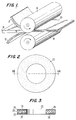
- the microballoon filled sheets 10 and 12 are positioned on either side of the PTFE sheet 14, and these sheets are calendered between calendering rolls 16 and 18 to form a laminate 20.
- the microballoon filled sheets 10 and 12 are each formed to be within the range of from 20-25% of the overall thickness of the resultant gasket material, while the central PTFE sheet 14 is within the range of from 50-60% of the overall gasket thickness. This is important, for if the sheets 10 and 12 are each formed to be below 20% of the overall gasket thickness, the finished composite sheet looses compressibility, while if they are formed to be above 25%, creep resistance and tensile strength are sacrificed in the finished product.
- the laminate 20 When initially formed, the laminate 20 is unsintered, but once formed, the laminate is sintered by subjecting it to temperatures above the gel point of PTFE.
- This gel point temperature is normally about 650°F, but before this temperature is reached, the PTFE in the sheets 10, 12 and 14 softens and becomes adhesive, and once the gel point is exceeded, a laminate no longer exists as the PTFE in the three original layers is now chemically fused. This eliminates any possibility of separation or delamination in the final gasketing material, as a unitary PTFE gasket has been formed.
- gaskets of any shape may then be formed from the gasketing material, with a round gasket 22 for use in sealing a pipe flange being shown.
- this round gasket has outer surface areas 24 and 25 which contain embedded microballoons 26 and a central area 28 which contains no microballoons but which imparts stability and tensile strength to the gasket.
- the central area 28 is within the range of from 50-60% of the total gasket thickness, while the outer areas 24 and 25 are each within the range of from 20-25% of the total gasket thickness.
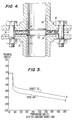
- the gasket 22 is shown in place between the flanges of two glass lined pipe sections 30 and 32.
- Each of these pipe sections includes a glass lining 34 which, as illustrated, extends out over the opposed flanges.
- the gasket 22 is positioned between the flanges, and then the flanges are bolted together by bolts 36.
- the surface of the glass lining 34 in glass lined pipes used for chemical applications is somewhat wavy, and this wavy surface must be effectively sealed.
- the bolts 36 load the pipe flanges to an extent sufficient to cause conventional chemically resistant gaskets, such as pure PTFE gaskets, to seal the wavy glass surface, the resultant pressure often destroys or damages the glass lining.
- the gasketing material used is PTFE completely filled with microballoons, tensile strength, resistance to creep relaxation or extrusion, and recovery characteristics are sacrificed in the interest of compressibility.
- the graph of Figure 5 illustrates the superior resistance to creep relaxation exhibited by the gasket material of the present invention when compared with a PTFE gasket wherein microballoons are mixed throughout the gasket.
- the gasket of the present invention was subjected to the same pressure load and temperature as a gasket of equal thickness with microballoons dispersed throughout, the results indicated by the graph of Figure 5 were obtained.
- Line A illustrates the creep relaxation experienced by the gasketing material of the present invention at various temperatures
- Line B illustrates a more significant creep relaxation which occurred with the microballoon filled gasketing material.
- the gasketing material of the present invention has an overall tested compressibility in the range of from 45-50% with an average compressibility of 46.6%. Maximum compressibility occurs in the outer areas 24 and 25 of the gasket which constitute from 40-50% of the total gasket thickness. This soft, deformable exterior promotes sealing at low bolt loads, and deformation occurs easily to fill irregularities in flange surfaces. The stable inner area 28 of the gasket minimizes traditional cold flow and provides excellent pressure resistance.
- the improved gasketing material of the present invention is industrial well applicable. It operates effectively in corrosive environments where temperatures within the range of from -212° C to + 260° C (-350°F to +500°F) are prevalent. Since the gasketing material does not comprise a laminate subject to separation, it can be employed in high vacuum surfaces without the fear of the gasket, or any part of the gasket, being pulled into the vessel or pipeline. The gasketing material operates effectively to seal the uneven surfaces of glass lined pipes without requiring flange pressure in an amount sufficient to damage the glass lining.
Landscapes
- Engineering & Computer Science (AREA)
- General Engineering & Computer Science (AREA)
- Mechanical Engineering (AREA)
- Sealing Material Composition (AREA)
- Gasket Seals (AREA)
- Laminated Bodies (AREA)
- Compositions Of Macromolecular Compounds (AREA)
Claims (15)
- Procédé pour former une matière de joint comprenant une étape de formation d'une première et seconde feuilles (10, 12) d'un matériau d'agrégation non-fritté comportant des particules (26) complètement enrobées, creuses, solides, compressibles, dispersées à l'intérieur du matériau et liées à celui-ci, puis une étape de formation d'une troisième feuille (14) faite d'une couche non frittée et de placement entre la première et la seconde feuilles (10, 12) pour former une structure à trois couches (20), caractérisé en ce que la première, la seconde et la troisième feuilles (10, 12, 14) sont formées de polytétrafluoréthylène non-fritté, la troisième feuille (14) étant formée avec une épaisseur qui est au moins deux fois celle de chacune desdites première et seconde feuilles (10, 12), et en ce que ladite structure à trois couches (20) est frittée à des températures au-dessus du point de gel du polytétrafluoréthèylène pour fusionner les trois couches en une structure de joint unitaire.
- Procédé selon la revendication 1, caractérisé en ce que la première et la seconde feuilles (10, 12) sont formées avec une épaisseur dans une plage de 20 % à 25 % de l'épaisseur totale de la structure à trois couches (20).
- Procédé selon la revendication 1, caractérisé en ce que la formation de chacune des première et seconde feuilles (10, 12) est telle que les particules creuses (26) forment de 15 % à 25 % du poids de ces feuilles.
- Procédé selon la revendication 1, caractérisé en ce que la formation des première et seconde feuilles (10, 12) est telle que les particules creuses (26) forment de 18 % à 21 % du poids de ces feuilles.
- Procédé selon la revendication 4, caractérisé en ce que chacune des première et seconde feuilles (10, 12) est formée, avec une épaisseur se situant dans une plage de 20 % à 25 % de l'épaisseur totale de la structure à trois couches (20).
- Procédé selon la revendication 1, caractérisé en ce que la formation de chacune des première et seconde feuilles (10, 12) est obtenue en mélangeant un polytétrafluoréthylène en poudre avec un liquide et des microbilles de verre (26), en mélangeant le composite résultant pour disperser les microbilles de verre, en filtrant le composite pour ôter de celui-ci l'excès de liquide et en limitant le composite pour former une feuille (10, 12) contenant des particules.
- Procédé selon la revendication 6, caractérisé en ce que les microbilles (26) sont ajoutées en quantité suffisante pour former 15 % à 25 % du poids desdites feuilles contenant des particules (10, 12).
- Procédé selon la revendication 7, caractérisé en ce que la première et la seconde feuilles (10, 12) sont formées avec une épaisseur se situant dans une plage de 20 % à 25 % de l'épaisseur totale de ladite structure à trois couches (20).
- Ensemble de joint hautement compressible comportant un corps unitaire (22), comprenant une première et une seconde surfaces espacées et opposées définissant entre elles une dimension d'épaisseur, selon le procédé des revendications de 1 à 8, caractérisé en ce que ledit corps (22) est formé essentiellement d'un unique matériau d'agrégation en polytétrafluoréthylène et comprenant au moins une première surface (24) adjacente à la première des surfaces externes et délimitée par cette surface, une seconde surface (28) unitaire avec la première surface (24), et une troisième surface (25) adjacente à la seconde surface externe et limitée par cette surface et formée unitairement avec ladite seconde surface (28), ladite seconde surface (28) étant agencée entre la première et la troisième surfaces (24, 25), et moins compressible en réponse à une force et d'une plus grande limite élastique à la traction que les première et troisième surfaces (24, 25), lesdites première et troisième surfaces (24, 25) contenant des particules (26) complètement enrobées, creuses, compressibles, dispersées à l'intérieur de ce matériau et liées à celui-ci, ladite seconde surface (28) ne comprenant pas de particules compressibles.
- Ensemble de joint hautement compressible selon la revendication 9, caractérisé en ce que la seconde surface (28) est plus épaisse que la première et la troisième surfaces (24, 25).
- Ensemble de joint hautement compressible selon la revendication 10, caractérisé en ce que les particules compressibles (26) forment de 15 % à 25 % du poids des première et troisième surfaces (24, 25).
- Ensemble de joint hautement compressible selon la revendication 11, caractérisé en ce que les particules compressibles (26) sont des microbilles de verre.
- Ensemble de joint hautement compressible selon les revendications 9 et 10, caractérisé en ce que la première et la troisième surfaces (24, 25) sont chacune d'une épaisseur se situant dans une plage de 20 % à 25 % de l'épaisseur totale du corps (22) dans ladite dimension d'épaisseur.
- Ensemble de joint hautement compressible selon la revendication 13, caractérisé en ce que les particules compressibles (26) forment de 15 % à 25 % du poids des première et troisième surfaces (24, 25).
- Ensemble de joint hautement compressible selon la revendication 14, caractérisé en ce que les particules compressibles sont des microbilles de verre (26), le corps (22) étant compressible dans ladite dimension d'épaisseur, dans une plage de 45 % à 50 %.
Priority Applications (1)
| Application Number | Priority Date | Filing Date | Title |
|---|---|---|---|
| AT89118272T ATE98345T1 (de) | 1988-10-04 | 1989-10-03 | Herstellungsverfahren fuer dichtungsmaterial und hochkomprimierbare abdichtung. |
Applications Claiming Priority (2)
| Application Number | Priority Date | Filing Date | Title |
|---|---|---|---|
| US07/253,185 US4900629A (en) | 1988-10-04 | 1988-10-04 | High compressibility gasket material |
| US253185 | 1988-10-04 |
Publications (2)
| Publication Number | Publication Date |
|---|---|
| EP0365871A1 EP0365871A1 (fr) | 1990-05-02 |
| EP0365871B1 true EP0365871B1 (fr) | 1993-12-08 |
Family
ID=22959229
Family Applications (1)
| Application Number | Title | Priority Date | Filing Date |
|---|---|---|---|
| EP19890118272 Expired - Lifetime EP0365871B1 (fr) | 1988-10-04 | 1989-10-03 | Méthode de production d'un matériau pour joints et joint hautement compressible |
Country Status (8)
| Country | Link |
|---|---|
| US (1) | US4900629A (fr) |
| EP (1) | EP0365871B1 (fr) |
| JP (1) | JPH02218784A (fr) |
| AT (1) | ATE98345T1 (fr) |
| AU (1) | AU622221B2 (fr) |
| CA (1) | CA1337873C (fr) |
| DE (1) | DE68911265T2 (fr) |
| ES (1) | ES2048807T3 (fr) |
Families Citing this family (40)
| Publication number | Priority date | Publication date | Assignee | Title |
|---|---|---|---|---|
| JPH0767693B2 (ja) * | 1988-03-08 | 1995-07-26 | 大日本インキ化学工業株式会社 | シートモールディングコンパウンドとその製造方法およびその成形品 |
| US5032335A (en) * | 1989-07-12 | 1991-07-16 | Mather Seal Company | Manufacture of sealing elements of composite sintered polymeric material |
| GB9003416D0 (en) * | 1990-02-15 | 1990-04-11 | Tba Industrial Products Ltd | Sheet sealing materials |
| US5354611A (en) * | 1990-02-21 | 1994-10-11 | Rogers Corporation | Dielectric composite |
| GB9206960D0 (en) * | 1992-03-31 | 1992-05-13 | Tba Industrial Products Ltd | Sheet sealing material |
| US5399307A (en) * | 1993-06-18 | 1995-03-21 | Dalton; Robert E. | Methods of compression molding two or more polytetrafluoroethylene resin layers |
| JPH09507802A (ja) * | 1994-10-31 | 1997-08-12 | ダブリュ.エル.ゴア アンド アソシエイツ,インコーポレイティド | ポリテトラフルオロエチレン剛性シート材 |
| US5964465A (en) * | 1996-03-13 | 1999-10-12 | W. L. Gore & Associates, Inc. | Low creep polytetrafluoroethylene form-in-place gasketing elements |
| US6485809B1 (en) | 1999-08-11 | 2002-11-26 | W. L. Gore & Associates Gmbh | Low stress to seal gasket |
| DE19964627B4 (de) * | 1999-08-31 | 2012-08-02 | STE Gesellschaft für Dichtungstechnik mbH | Dichtung und Verfahren zu deren Herstellung |
| DE19941410B4 (de) * | 1999-08-31 | 2011-05-05 | STE Gesellschaft für Dichtungstechnik mbH | Beschichtung und Verfahren zu deren Herstellung |
| DE10019678A1 (de) | 2000-04-19 | 2001-10-25 | Sgl Carbon Ag | Flächiges Halbzeug und Verfahren zu dessen Herstellung |
| JP2002243041A (ja) * | 2001-02-19 | 2002-08-28 | Japan Gore Tex Inc | テープ状シール材及びその製造方法 |
| US6790213B2 (en) * | 2002-01-07 | 2004-09-14 | C.R. Bard, Inc. | Implantable prosthesis |
| DE10347081A1 (de) * | 2003-10-10 | 2005-05-12 | Frenzelit Werke Gmbh & Co Kg | Flachdichtungswerkstoff mit Zuschlagsstoff zur aktiven topographischen Regulierung der Krafteinleitung |
| WO2005057056A2 (fr) * | 2003-12-05 | 2005-06-23 | Garlock Sealing Technologies, Llc | Joint de forme non arrondie avec elements d'assistance d'installation |
| DE102004041043B3 (de) * | 2004-08-25 | 2006-03-30 | Klinger Ag | Laminiertes Dichtungsmaterial und Verfahren zu seiner Herstellung |
| US7314898B2 (en) * | 2004-12-29 | 2008-01-01 | 3M Innovative Properties Company | Microsphere-filled polytetrafluoroethylene compositions |
| US7455301B2 (en) * | 2006-03-02 | 2008-11-25 | Virginia Sealing Products, Inc. | Seamless corrugated insert gasket and method of forming the same |
| US8852486B2 (en) * | 2006-11-06 | 2014-10-07 | Garlock Sealing Technologies, Llc | Low-stress molded gasket and method of making same |
| CN101627081A (zh) * | 2007-02-06 | 2010-01-13 | 卡勒克密封技术有限责任公司 | 充填有氮化硼的聚四氟乙烯 |
| CA2966657C (fr) | 2008-10-03 | 2019-07-02 | C.R. Bard, Inc. | Prothese implantable |
| US9371129B1 (en) | 2011-02-03 | 2016-06-21 | 4M Company | Lightweight aircraft seal material |
| US9701388B2 (en) | 2011-05-11 | 2017-07-11 | Aviation Devices & Electronic Components, Llc | Gasket having a pliable resilient body with a perimeter having characteristics different than the body |
| WO2012174426A1 (fr) | 2011-06-17 | 2012-12-20 | Aviation Devices & Electronic Components, L.L.C. | Joint d'étanchéité collant sur un seul côté |
| US8863625B2 (en) | 2011-06-21 | 2014-10-21 | Aviation Devices & Electronics Components, LLC | Elastomeric gasket squeeze out removal method and kit |
| US8691033B1 (en) | 2011-07-06 | 2014-04-08 | Aviation Devices & Electronic Components, Llc | Positioning a workpiece on a sticky gasket |
| US9702464B1 (en) | 2011-10-03 | 2017-07-11 | The Patent Well LLC | Non-planar stick gaskets for receipt between a base and a workpiece |
| DE102011116162A1 (de) * | 2011-10-14 | 2013-04-18 | Eagleburgmann Germany Gmbh & Co. Kg | Gleitring einer Gleitringdichtungsanordnung mit laufzeitverlängernden Eigenschaften sowie Verfahren zu dessen Herstellung |
| US9751244B2 (en) | 2012-05-15 | 2017-09-05 | The Patent Well LLC | Elastomeric gasket for fuel access door of an aircraft wing and a method for making the same |
| US9303447B1 (en) | 2012-05-15 | 2016-04-05 | Aviation Devices & Electronic Components LLC | Elastomeric gasket for fuel access door of an aircraft wing and a method for making the same |
| US9671023B2 (en) | 2012-07-10 | 2017-06-06 | Aviation Devices & Electronic Components, Llc | Spacer and gasket assembly for use on an aircraft |
| US9016697B2 (en) | 2012-07-10 | 2015-04-28 | Aviation Devices & Electronic Components, Llc | Spacer and gasket assembly for use on an aircraft |
| FR3008339B1 (fr) * | 2013-07-15 | 2015-08-07 | Commissariat Energie Atomique | Procede de mise en forme d'une plaque en un polytetrafluoroethylene fritte et restructure et ses applications |
| US20150115548A1 (en) * | 2013-10-29 | 2015-04-30 | Virginia Sealing Products, Inc. | Composite gasket |
| CA2981852A1 (fr) * | 2015-04-08 | 2016-10-13 | Aviation Devices & Electronic Components, L.L.C. | Treillis metallique comportant un revetement de conversion a faible resistance electrique pour une utilisation avec des structures d'aeronef |
| CN107513271A (zh) * | 2017-08-31 | 2017-12-26 | 太仓卡斯特姆新材料有限公司 | 一种低压缩抗变形橡胶密封圈 |
| CN109501424B (zh) * | 2018-12-26 | 2023-09-12 | 江苏金由新材料有限公司 | 一种ptfe复合密封垫片及其制备工艺 |
| EP4211359A2 (fr) | 2020-09-08 | 2023-07-19 | Dover Pumps & Process Solutions Segment, Inc. | Structures composites à gradient fonctionnel |
| WO2022056162A1 (fr) | 2020-09-09 | 2022-03-17 | Waukesha Bearings Corporation | Structures composites pour des systèmes de compresseur de gaz à pistons |
Family Cites Families (6)
| Publication number | Priority date | Publication date | Assignee | Title |
|---|---|---|---|---|
| US2299805A (en) * | 1941-12-26 | 1942-10-27 | Detroit Gasket & Mfg Company | Packing |
| US2428771A (en) * | 1944-06-16 | 1947-10-14 | Armstrong Cork Co | Method of making sheet gasket material |
| US2584959A (en) * | 1948-09-14 | 1952-02-05 | Raybestos Manhattan Inc | Cork containing composite sheet material |
| US3231460A (en) * | 1963-03-21 | 1966-01-25 | Raybestos Manhattan Inc | Sheet material |
| US3524794A (en) * | 1966-08-04 | 1970-08-18 | Minnesota Mining & Mfg | Fluid sealing gasket |
| US3901315A (en) * | 1974-04-11 | 1975-08-26 | Del Norte Technology | Downhole valve |
-
1988
- 1988-10-04 US US07/253,185 patent/US4900629A/en not_active Expired - Lifetime
-
1989
- 1989-09-28 CA CA 613969 patent/CA1337873C/fr not_active Expired - Lifetime
- 1989-09-28 AU AU42414/89A patent/AU622221B2/en not_active Expired
- 1989-10-02 JP JP1255367A patent/JPH02218784A/ja active Pending
- 1989-10-03 ES ES89118272T patent/ES2048807T3/es not_active Expired - Lifetime
- 1989-10-03 DE DE68911265T patent/DE68911265T2/de not_active Expired - Fee Related
- 1989-10-03 EP EP19890118272 patent/EP0365871B1/fr not_active Expired - Lifetime
- 1989-10-03 AT AT89118272T patent/ATE98345T1/de not_active IP Right Cessation
Also Published As
| Publication number | Publication date |
|---|---|
| ATE98345T1 (de) | 1993-12-15 |
| EP0365871A1 (fr) | 1990-05-02 |
| US4900629A (en) | 1990-02-13 |
| AU622221B2 (en) | 1992-04-02 |
| JPH02218784A (ja) | 1990-08-31 |
| AU4241489A (en) | 1990-04-12 |
| ES2048807T3 (es) | 1994-04-01 |
| DE68911265D1 (de) | 1994-01-20 |
| CA1337873C (fr) | 1996-01-02 |
| DE68911265T2 (de) | 1994-06-09 |
Similar Documents
| Publication | Publication Date | Title |
|---|---|---|
| EP0365871B1 (fr) | Méthode de production d'un matériau pour joints et joint hautement compressible | |
| US4961891A (en) | Method of making high compressibility gasket material | |
| US5551706A (en) | Composite gasket for sealing flanges and method for making and using same | |
| US6092811A (en) | Hybrid gasket | |
| US5421594A (en) | Gasket | |
| US5492336A (en) | O-ring gasket material and method for making and using same | |
| CA2157283C (fr) | Garniture d'etancheite en materiau composite enveloppee | |
| US5615896A (en) | Rubber encapsulated vee ring seal | |
| US4913951A (en) | Fabrication of reinforced PTFE gasketing material | |
| US9618122B2 (en) | Low-stress molded gasket and method of making same | |
| US4214761A (en) | Packing construction | |
| US5792525A (en) | Creep resistant shaped article of densified expanded polytetrafluoroethylene | |
| PL188472B1 (pl) | Uszczelka płaska z tworzywa warstwowego | |
| US20030090067A1 (en) | Rubber and wire mesh ring | |
| WO1995030851A1 (fr) | Garniture d'etancheite | |
| KR960701322A (ko) | 시이트상 가스킷 | |
| US20030003290A1 (en) | Sealing material in the form of tape, and production thereof | |
| US6399204B1 (en) | Flexible multi-layer gasketing product | |
| WO2007087643A2 (fr) | Joint enroule en spirale anti-flambage a faible tension | |
| JP2005337401A (ja) | フッ素樹脂包みガスケット | |
| JP2004245286A (ja) | 接触面積が低減されたガスケット | |
| JP2003106456A (ja) | フッ素樹脂包みガスケット | |
| KR101094149B1 (ko) | 팽창흑연제 개스킷 및 그 제조방법 | |
| JPH08109368A (ja) | 複合ガスケット | |
| US20230243426A1 (en) | Composite gasket with non-metallic insert |
Legal Events
| Date | Code | Title | Description |
|---|---|---|---|
| PUAI | Public reference made under article 153(3) epc to a published international application that has entered the european phase |
Free format text: ORIGINAL CODE: 0009012 |
|
| AK | Designated contracting states |
Kind code of ref document: A1 Designated state(s): AT BE CH DE ES FR GB GR IT LI LU NL SE |
|
| 17P | Request for examination filed |
Effective date: 19901019 |
|
| 17Q | First examination report despatched |
Effective date: 19920428 |
|
| GRAA | (expected) grant |
Free format text: ORIGINAL CODE: 0009210 |
|
| AK | Designated contracting states |
Kind code of ref document: B1 Designated state(s): AT BE CH DE ES FR GB GR IT LI LU NL SE |
|
| PG25 | Lapsed in a contracting state [announced via postgrant information from national office to epo] |
Ref country code: BE Effective date: 19931208 |
|
| REF | Corresponds to: |
Ref document number: 98345 Country of ref document: AT Date of ref document: 19931215 Kind code of ref document: T |
|
| REF | Corresponds to: |
Ref document number: 68911265 Country of ref document: DE Date of ref document: 19940120 |
|
| ITF | It: translation for a ep patent filed | ||
| ET | Fr: translation filed | ||
| REG | Reference to a national code |
Ref country code: ES Ref legal event code: FG2A Ref document number: 2048807 Country of ref document: ES Kind code of ref document: T3 |
|
| REG | Reference to a national code |
Ref country code: GR Ref legal event code: FG4A Free format text: 3010987 |
|
| PLBE | No opposition filed within time limit |
Free format text: ORIGINAL CODE: 0009261 |
|
| STAA | Information on the status of an ep patent application or granted ep patent |
Free format text: STATUS: NO OPPOSITION FILED WITHIN TIME LIMIT |
|
| 26N | No opposition filed | ||
| EAL | Se: european patent in force in sweden |
Ref document number: 89118272.7 |
|
| REG | Reference to a national code |
Ref country code: CH Ref legal event code: PUE Owner name: GARLOCK, INC. TRANSFER- COLTEC NORTH CAROLINA INC. Ref country code: CH Ref legal event code: NV Representative=s name: BOVARD AG PATENTANWAELTE |
|
| PGFP | Annual fee paid to national office [announced via postgrant information from national office to epo] |
Ref country code: AT Payment date: 19990920 Year of fee payment: 11 |
|
| PGFP | Annual fee paid to national office [announced via postgrant information from national office to epo] |
Ref country code: CH Payment date: 19990924 Year of fee payment: 11 |
|
| PGFP | Annual fee paid to national office [announced via postgrant information from national office to epo] |
Ref country code: ES Payment date: 19991008 Year of fee payment: 11 |
|
| PGFP | Annual fee paid to national office [announced via postgrant information from national office to epo] |
Ref country code: LU Payment date: 19991013 Year of fee payment: 11 |
|
| PGFP | Annual fee paid to national office [announced via postgrant information from national office to epo] |
Ref country code: GR Payment date: 19991020 Year of fee payment: 11 |
|
| REG | Reference to a national code |
Ref country code: FR Ref legal event code: TP |
|
| PG25 | Lapsed in a contracting state [announced via postgrant information from national office to epo] |
Ref country code: LU Free format text: LAPSE BECAUSE OF NON-PAYMENT OF DUE FEES Effective date: 20001003 Ref country code: AT Free format text: LAPSE BECAUSE OF NON-PAYMENT OF DUE FEES Effective date: 20001003 |
|
| PG25 | Lapsed in a contracting state [announced via postgrant information from national office to epo] |
Ref country code: ES Free format text: LAPSE BECAUSE OF NON-PAYMENT OF DUE FEES Effective date: 20001004 |
|
| PG25 | Lapsed in a contracting state [announced via postgrant information from national office to epo] |
Ref country code: LI Free format text: LAPSE BECAUSE OF NON-PAYMENT OF DUE FEES Effective date: 20001031 Ref country code: GR Free format text: LAPSE BECAUSE OF NON-PAYMENT OF DUE FEES Effective date: 20001031 Ref country code: CH Free format text: LAPSE BECAUSE OF NON-PAYMENT OF DUE FEES Effective date: 20001031 |
|
| REG | Reference to a national code |
Ref country code: CH Ref legal event code: PL |
|
| REG | Reference to a national code |
Ref country code: GB Ref legal event code: IF02 |
|
| PGFP | Annual fee paid to national office [announced via postgrant information from national office to epo] |
Ref country code: FR Payment date: 20020918 Year of fee payment: 14 |
|
| PGFP | Annual fee paid to national office [announced via postgrant information from national office to epo] |
Ref country code: SE Payment date: 20020919 Year of fee payment: 14 Ref country code: NL Payment date: 20020919 Year of fee payment: 14 |
|
| PGFP | Annual fee paid to national office [announced via postgrant information from national office to epo] |
Ref country code: GB Payment date: 20020927 Year of fee payment: 14 |
|
| PGFP | Annual fee paid to national office [announced via postgrant information from national office to epo] |
Ref country code: DE Payment date: 20021031 Year of fee payment: 14 |
|
| PG25 | Lapsed in a contracting state [announced via postgrant information from national office to epo] |
Ref country code: GB Free format text: LAPSE BECAUSE OF NON-PAYMENT OF DUE FEES Effective date: 20031003 |
|
| PG25 | Lapsed in a contracting state [announced via postgrant information from national office to epo] |
Ref country code: SE Free format text: LAPSE BECAUSE OF NON-PAYMENT OF DUE FEES Effective date: 20031004 |
|
| REG | Reference to a national code |
Ref country code: ES Ref legal event code: FD2A Effective date: 20011113 |
|
| PG25 | Lapsed in a contracting state [announced via postgrant information from national office to epo] |
Ref country code: NL Free format text: LAPSE BECAUSE OF NON-PAYMENT OF DUE FEES Effective date: 20040501 Ref country code: DE Free format text: LAPSE BECAUSE OF NON-PAYMENT OF DUE FEES Effective date: 20040501 |
|
| GBPC | Gb: european patent ceased through non-payment of renewal fee |
Effective date: 20031003 |
|
| EUG | Se: european patent has lapsed | ||
| PG25 | Lapsed in a contracting state [announced via postgrant information from national office to epo] |
Ref country code: FR Free format text: LAPSE BECAUSE OF NON-PAYMENT OF DUE FEES Effective date: 20040630 |
|
| NLV4 | Nl: lapsed or anulled due to non-payment of the annual fee |
Effective date: 20040501 |
|
| REG | Reference to a national code |
Ref country code: FR Ref legal event code: ST |
|
| PG25 | Lapsed in a contracting state [announced via postgrant information from national office to epo] |
Ref country code: IT Free format text: LAPSE BECAUSE OF NON-PAYMENT OF DUE FEES Effective date: 20051003 |