EP0540499A2 - Stufenloses Reissrollengetriebe - Google Patents
Stufenloses Reissrollengetriebe Download PDFInfo
- Publication number
- EP0540499A2 EP0540499A2 EP93100533A EP93100533A EP0540499A2 EP 0540499 A2 EP0540499 A2 EP 0540499A2 EP 93100533 A EP93100533 A EP 93100533A EP 93100533 A EP93100533 A EP 93100533A EP 0540499 A2 EP0540499 A2 EP 0540499A2
- Authority
- EP
- European Patent Office
- Prior art keywords
- transmission
- toric
- traction roller
- shaft
- pivot
- Prior art date
- Legal status (The legal status is an assumption and is not a legal conclusion. Google has not performed a legal analysis and makes no representation as to the accuracy of the status listed.)
- Withdrawn
Links
- 230000005540 biological transmission Effects 0.000 title claims abstract description 94
- 230000033001 locomotion Effects 0.000 claims abstract description 9
- 230000000977 initiatory effect Effects 0.000 claims abstract description 3
- 230000007246 mechanism Effects 0.000 claims description 10
- 230000008878 coupling Effects 0.000 claims description 2
- 238000010168 coupling process Methods 0.000 claims description 2
- 238000005859 coupling reaction Methods 0.000 claims description 2
- 239000012530 fluid Substances 0.000 description 6
- 239000002184 metal Substances 0.000 description 2
- 230000006835 compression Effects 0.000 description 1
- 238000007906 compression Methods 0.000 description 1
- 230000036316 preload Effects 0.000 description 1
Images




Classifications
-
- F—MECHANICAL ENGINEERING; LIGHTING; HEATING; WEAPONS; BLASTING
- F16—ENGINEERING ELEMENTS AND UNITS; GENERAL MEASURES FOR PRODUCING AND MAINTAINING EFFECTIVE FUNCTIONING OF MACHINES OR INSTALLATIONS; THERMAL INSULATION IN GENERAL
- F16H—GEARING
- F16H15/00—Gearings for conveying rotary motion with variable gear ratio, or for reversing rotary motion, by friction between rotary members
- F16H15/02—Gearings for conveying rotary motion with variable gear ratio, or for reversing rotary motion, by friction between rotary members without members having orbital motion
- F16H15/04—Gearings providing a continuous range of gear ratios
- F16H15/06—Gearings providing a continuous range of gear ratios in which a member A of uniform effective diameter mounted on a shaft may co-operate with different parts of a member B
- F16H15/32—Gearings providing a continuous range of gear ratios in which a member A of uniform effective diameter mounted on a shaft may co-operate with different parts of a member B in which the member B has a curved friction surface formed as a surface of a body of revolution generated by a curve which is neither a circular arc centered on its axis of revolution nor a straight line
- F16H15/36—Gearings providing a continuous range of gear ratios in which a member A of uniform effective diameter mounted on a shaft may co-operate with different parts of a member B in which the member B has a curved friction surface formed as a surface of a body of revolution generated by a curve which is neither a circular arc centered on its axis of revolution nor a straight line with concave friction surface, e.g. a hollow toroid surface
- F16H15/38—Gearings providing a continuous range of gear ratios in which a member A of uniform effective diameter mounted on a shaft may co-operate with different parts of a member B in which the member B has a curved friction surface formed as a surface of a body of revolution generated by a curve which is neither a circular arc centered on its axis of revolution nor a straight line with concave friction surface, e.g. a hollow toroid surface with two members B having hollow toroid surfaces opposite to each other, the member or members A being adjustably mounted between the surfaces
-
- F—MECHANICAL ENGINEERING; LIGHTING; HEATING; WEAPONS; BLASTING
- F16—ENGINEERING ELEMENTS AND UNITS; GENERAL MEASURES FOR PRODUCING AND MAINTAINING EFFECTIVE FUNCTIONING OF MACHINES OR INSTALLATIONS; THERMAL INSULATION IN GENERAL
- F16H—GEARING
- F16H15/00—Gearings for conveying rotary motion with variable gear ratio, or for reversing rotary motion, by friction between rotary members
- F16H15/02—Gearings for conveying rotary motion with variable gear ratio, or for reversing rotary motion, by friction between rotary members without members having orbital motion
- F16H15/04—Gearings providing a continuous range of gear ratios
- F16H15/06—Gearings providing a continuous range of gear ratios in which a member A of uniform effective diameter mounted on a shaft may co-operate with different parts of a member B
- F16H15/32—Gearings providing a continuous range of gear ratios in which a member A of uniform effective diameter mounted on a shaft may co-operate with different parts of a member B in which the member B has a curved friction surface formed as a surface of a body of revolution generated by a curve which is neither a circular arc centered on its axis of revolution nor a straight line
- F16H15/36—Gearings providing a continuous range of gear ratios in which a member A of uniform effective diameter mounted on a shaft may co-operate with different parts of a member B in which the member B has a curved friction surface formed as a surface of a body of revolution generated by a curve which is neither a circular arc centered on its axis of revolution nor a straight line with concave friction surface, e.g. a hollow toroid surface
- F16H15/38—Gearings providing a continuous range of gear ratios in which a member A of uniform effective diameter mounted on a shaft may co-operate with different parts of a member B in which the member B has a curved friction surface formed as a surface of a body of revolution generated by a curve which is neither a circular arc centered on its axis of revolution nor a straight line with concave friction surface, e.g. a hollow toroid surface with two members B having hollow toroid surfaces opposite to each other, the member or members A being adjustably mounted between the surfaces
- F16H2015/383—Gearings providing a continuous range of gear ratios in which a member A of uniform effective diameter mounted on a shaft may co-operate with different parts of a member B in which the member B has a curved friction surface formed as a surface of a body of revolution generated by a curve which is neither a circular arc centered on its axis of revolution nor a straight line with concave friction surface, e.g. a hollow toroid surface with two members B having hollow toroid surfaces opposite to each other, the member or members A being adjustably mounted between the surfaces with two or more sets of toroid gearings arranged in parallel
Definitions
- the invention relates to an infinitely variable traction roller transmission in which power is transmitted through traction rollers pivotally supported in a housing between toric input and output discs.
- the traction rollers are mounted on support structures which, when pivoted, cause engagement of the traction rollers with the toric discs in circles of varying diameters depending on the desired transmission ratio.
- the pivotal traction roller support structures are so supported that they can be moved axially for initiating a change in the transmission ratio.
- too traction rollers may be supported opposite one another by flexible tension sheets as shown in U.S. Patent 4,086,820 which issued May 2, 1978 to Charles E. Kraus.
- the traction roller support members are pivotally supported with respect to the transmission housing by means of antifriction bearing segments which are disposed at opposite ends of the support members and directly mounted on the housing.
- Such bearing segments however are quite expensive and therefore the arrangement as a whole becomes too expensive for small transmissions.
- each traction roller is supported by a pivotal support trunnion which has support rollers disposed at opposite ends thereof and supported on partial circular tracks disposed on the housing's inner surface for direct trunnion support.
- the traction rollers are supported on the pivot trunnions by force transmitting means which, for inexpensive transmissions, include stacks of Belleville springs.
- the housing tracks may have a center of curvature which is slightly off-set with regard to the pivot axis of the trunnions in order to provide greater compression of the Belleville spring, that is, greater disc engagement forces in one pivotal end position of the pivot trunnions than in their opposite pivotal end positions.
- Such support structure is relatively inexpensive and yet with the arrangement with displaced support track the engagement forces applied to the traction rollers by the traction roller support structure depend on the pivot position of the traction roller support trunnion such that--depending on the use of the transmission--they are relatively high in one pivot end position and relatively low in the opposite pivot end position.
- This arrangement although relatively simple and inexpensive, still requires a high pressure fluid source and high pressure operating cylinders and pistons for transmission ratio control and although the high pressure control structures are relatively simple they were the cause of a number of operational difficulties and furthermore they require a special high pressure fluid pump since operating fluids of similarly high pressures are generally not available.
- an infinitely variable traction roller transmission comprising: a housing; coaxial input and output shafts rotatably supported in said housing; a main transmission shaft rotatably supported in said housing in parallel spaced relationship with said input and output shafts, said main transmission shaft being operatively connected to said input shaft for rotation therewith; two toric traction roller transmission structures including outer and inner toric discs disposed on said main shaft and having their axially outer toric discs mounted for rotation with said main transmission shaft and their inner toric discs mounted for rotation with a first hollow transmission shaft surrounding said main transmission shaft between said toric traction roller transmission structures, each of said toric traction roller transmission structures including motion transmitting traction rollers in engagement with the toric discs of said toric traction roller transmission structures and supported on pivot trunnions disposed opposite one another with respect to a plane defined by the axes of said input and output and said main transmission shafts and including means associated with said trunnions for causing pivoting of said trunnions in
- a simple traction roller transmission as shown in Fig. 1 consists of a housing 10 having coaxial input and output shafts 12, 14 rotatably supported therein by bearings 16 and 18. Associated with the input and output shafts 12, 14 are toric discs 20, 22 which are so arranged opposite one another that a toric cavity 24 of circular cross-section is defined therebetween. Within the toric cavity 24 traction rollers 26, 28 are rotatably supported in engagement with the toric traction discs 20, 22. The traction rollers 26, 28 are supported in the housing 10 by pivot trunnions 30 and 32 which are pivotally supported directly on the housing walls by way of trunnion rollers 34 and 36 running on hard metal track members 38, 40 received in track cavities 42, 44 formed in the housing 10.
- Each of the pivot trunnions 30, 32 carries a traction roller bearing 46 for rotatably supporting the associated traction rollers 26, 28 which are forced into firm engagement with the traction discs 20 and 22 by way of the trunnion rollers 34, 36, the traction discs 20 and 22 being axially supported by axial thrust bearings 48 and 50.
- the engagement forces of the traction rollers 26, 28 with the toric traction discs 20, 22 depend on the loading applied by the track members 38, 40 which are adjustably mounted by preload adjustment screws 52.
- the circular support grooves 54 in the track members 38, 40 may be slightly eccentric with respect to the center circle of curvature of the toric cavity 24 in order to provide larger contact forces for the traction rollers in one pivotal end position of the pivot trunnions 30 and 32, specifically, in the position for lowest output shaft speed and highest output shaft torque as shown in Fig. 1.
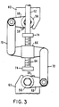
- Fig. 2 shows the support arrangement for the pivot trunnions 30 and 32 which at their control ends 56 are slidably engaged by appropriate grooves 58 formed in inwardly projecting housing wall portions 60. They are held in position by a ratio control rod or screw 62 supported in the housing 10 and provided with a threaded portion 64 carrying an adjustment member 66 to which the ends 56 of the pivot trunnions 30 and 32 are linked as shown clearly in Fig. 3.
- the pivot trunnion ends 56 have precess arms 68 mounted thereon so as to project radially in opposite directions with respect to the pivot axes of the trunnions and the axis of the control rod 62.
- the ends of the precess arms 68 are linked to the oppositely projecting ends of the adjusting member 66 by links 70.
- the transmission ratio can be controlled with this arrangement in a simple manner: Rotating the control rod 62 by way of a hand wheel 72, for example, causes the adjusting member 66 to move axially on the threaded portion 64 and, by way of links 70 provides for tilting of the pivot trunnions 30 and 32 and the traction rollers 26, 28 into a precessing position with respect to the toric discs 20, 22.
- the precessing position causes the traction rollers 26, 28 to walk to different circles of engagement with the toric discs 20, 22, to a larger circle of engagement with one and a smaller circle of engagement with the other, thereby pivoting the pivot trunnions 30 and 32 while changing the transmission ratio.
- Stop members 74 may be provided on the control shaft which determine the pivot end positions of the pivot trunnions, that is, the transmission ratio limits.
- Figs. 1 to 3 The arrangement disclosed with regard to Figs. 1 to 3 is a simple mechanical arrangement which is therefore inexpensive and reliable. However arrangements capable of transmitting substantially more power are feasible with relatively little more complicated arrangements, for example, as shown in Fig. 4.
- twin traction roller structures are utilized for higher power transmissions and in order to avoid the need for heavy and expensive axial thrust bearings for the toric discs.
- the two outer toric discs 102 and 104 are firmly mounted on the main transmission shaft 106 by way of mounting sleeves 108 and 110, the sleeve 108 being provided with a gear structure to be driven thereby.
- the inner discs 112 and 114 are mounted on a hollow transmission shaft 116 through which the main transmission shaft 106 extends and which carries an output gear 118, the hollow transmission shaft 116 being supported by bearings 120.
- the metal track members 122 for the traction roller support trunnion rollers 123 are provided with an adjustable backup structure including a wedge 124 disposed on an inclined backup plate 126 and including needle bearing structures 128 to facilitate wedging movement.
- Pistons 130 disposed in cylinders 132 abut the wedges for hydraulic operation of the wedges so as to provide the required contact forces between the traction rollers 134 and the discs 102, 104 and 112, 114. In this manner the hydraulic fluid pressure necessary for operating the pistons 130 is only relatively low which eliminates the need for high pressure fluid pumps and high pressure piston seals. Also jerky motions are not directly applied to the pistons.
- the transmission ratio control arrangement is essentially the same as the one shown in Fig. 3 for a single-unit traction roller transmission.
- the operating mechanisms for the two toric disc structures are attached to the opposite ends of an operating arm 150 to which the individual adjustment members 166 are mounted so that they are movable in unison by the operating arm and the mechanism for moving the operating arm 150.
- this mechanism consists of a threaded rod 162 but it may also be a hydraulic mechanism.
- Fig. 6 is a cross-sectional view along line VI-VI of Fig. 5 which cross-sectional view gives a full view of the transmission mechanism. The figure does not show the housing since it is not needed for an understanding.
- Fig. 6 shows the transmission input shaft 170 which at its outer end carries an input gear 172 which is in engagement with the gear structure 174 on the sleeve 108 of Fig. 5.
- the input shaft 170 is provided with a clutching structure 176 which includes a clutch bell 178 mounted on one end of an intermediate shaft 180 which extends through a hollow transmission shaft 182.
- the hollow transmission shaft 182 carries a gear 184 which is in engagement with the gear 118 mounted on the hollow traction roller transmission shaft 116 and which is driven thereby at a relative speed, variable depending on the ratio setting of pivotal traction rollers 134.
- the hollow transmission shaft 182 is provided at its end with a sun roller structure 186 which forms the center roller of a planetary type traction roller transmission of the type disclosed in applicant's patent application Serial No. 07/188,132.
- the planetary type traction roller transmission includes a traction ring 188 which is mounted for rotation with the transmission output shaft 190 and has a race 192 spaced from the surface of the sun roller 186 with planetary rollers 194 being disposed in the annular space between the traction ring 188 and the sun roller 186.
- the planetary rollers 194 are supported by a carrier 196 which is firmly mounted on the other end of the intermediate shaft 180.
- the planetary roller carrier 196 is either rotated together with the input shaft 170 (forward) or it is held non-rotatable (for reverse) under the control of the clutch structure 176.
- the intermediate transmission shaft 180 is operatively connected to the clutch plate support member 206 which is mounted on the input shaft 170 so that the intermediate shaft 180 and the planetary traction roller carrier rotate with the input shaft for forward rotation of the output shaft 190. If however the clutch plates 200 and 202 are disengaged and the reverse brake band 208 engages the carrier 210 for the clutch plates 202, which carrier is connected with the clutch bell 178, the intermediate shaft 180 is locked and so is the planetary traction roller carrier 196 which then provides for reverse rotation of the ring 188 and the output shaft 190.
- Fig. 6 shows the arrangement as shown in Fig. 6 how space-efficient the arrangement actually is. It is seen that the clutch structure 176 extends into the otherwise unused toric space defined between the toric discs of one set of toric transmission discs and the planetary traction roller ring 188 extends into the toric space defined between the toric discs of the other set of toric transmission discs so that the distance between the two sets of shafts and also the transmission volume are only relatively small.
- Fig. 6 also shows the ratio control mechanism for the two toric traction roller transmission structures wherein, as also shown in Fig. 5, one operating arm 150 has its opposite ends connected to the two ratio control mechanisms for concurrent operation thereof, the operating arm 150 being movable by the rod 162.
- the rod 162 may be movable by mechanical means or it may be operable by hydraulic means such as a hydraulic cylinder and piston structure which preferably is large enough such that its operating fluid pressure requirements are essentially the same as those of the operating pistons and cylinders 130, 132 for the wedges 124.
- the support rollers 36 may be slightly curved in axial direction as shown in Fig. 2 or, although a planetary type traction roller transmission is shown, a gear type planetary traction roller transmission may be utilized.
Landscapes
- Engineering & Computer Science (AREA)
- General Engineering & Computer Science (AREA)
- Mechanical Engineering (AREA)
- Friction Gearing (AREA)
Applications Claiming Priority (2)
| Application Number | Priority Date | Filing Date | Title |
|---|---|---|---|
| US259043 | 1988-10-17 | ||
| US07/259,043 US4964312A (en) | 1988-10-17 | 1988-10-17 | Infinitely variable traction roller transmission |
Related Parent Applications (1)
| Application Number | Title | Priority Date | Filing Date |
|---|---|---|---|
| EP89118275.0 Division | 1989-10-03 |
Publications (2)
| Publication Number | Publication Date |
|---|---|
| EP0540499A2 true EP0540499A2 (de) | 1993-05-05 |
| EP0540499A3 EP0540499A3 (en) | 1993-07-28 |
Family
ID=22983265
Family Applications (2)
| Application Number | Title | Priority Date | Filing Date |
|---|---|---|---|
| EP19930100533 Withdrawn EP0540499A3 (en) | 1988-10-17 | 1989-10-03 | Infinitely variable traction roller transmission |
| EP89118275A Expired - Lifetime EP0365872B1 (de) | 1988-10-17 | 1989-10-03 | Stufenloses Reibrad-Getriebe |
Family Applications After (1)
| Application Number | Title | Priority Date | Filing Date |
|---|---|---|---|
| EP89118275A Expired - Lifetime EP0365872B1 (de) | 1988-10-17 | 1989-10-03 | Stufenloses Reibrad-Getriebe |
Country Status (4)
| Country | Link |
|---|---|
| US (1) | US4964312A (de) |
| EP (2) | EP0540499A3 (de) |
| DE (1) | DE68908334T2 (de) |
| ES (1) | ES2044007T3 (de) |
Cited By (2)
| Publication number | Priority date | Publication date | Assignee | Title |
|---|---|---|---|---|
| DE10034453A1 (de) * | 2000-07-15 | 2002-01-24 | Zahnradfabrik Friedrichshafen | Stufenloses Reibradgetriebe |
| US8083637B2 (en) | 2006-06-02 | 2011-12-27 | Nsk Ltd. | Toroidal continuously variable transmission |
Families Citing this family (49)
| Publication number | Priority date | Publication date | Assignee | Title |
|---|---|---|---|---|
| US4911030A (en) * | 1989-01-30 | 1990-03-27 | Excelermatic Inc. | Traction roller transmission ratio control arrangement |
| US4996891A (en) * | 1989-10-30 | 1991-03-05 | Excelermatic Inc. | Infinitely variable traction roller transmission |
| US4974466A (en) * | 1989-11-27 | 1990-12-04 | Excelermatic Inc. | Infinitely variable traction roller transmission |
| US5203748A (en) * | 1990-05-09 | 1993-04-20 | Canon Kabushiki Kaisha | Rotary driving system and robot operating thereon |
| US5085089A (en) * | 1991-02-06 | 1992-02-04 | Excelermatic Inc. | Infinitely variable traction roller transmission |
| US5368529A (en) * | 1992-06-29 | 1994-11-29 | Nsk Ltd. | Toroidal type continuously variable transmission |
| US5540631A (en) * | 1992-12-16 | 1996-07-30 | The Torax Company, Inc. | Continuously variable transmission with a hydraulic control system |
| US5330396A (en) * | 1992-12-16 | 1994-07-19 | The Torax Company, Inc. | Loading device for continuously variable transmission |
| JP3496350B2 (ja) | 1995-07-24 | 2004-02-09 | 日産自動車株式会社 | トロイダル型無段変速機 |
| US5916057A (en) * | 1997-05-27 | 1999-06-29 | Excelermalic Inc. | Zero spin infinitely variable traction roller transmission |
| JP2003049914A (ja) * | 2001-08-07 | 2003-02-21 | Nsk Ltd | トロイダル型無段変速機 |
| US7011600B2 (en) | 2003-02-28 | 2006-03-14 | Fallbrook Technologies Inc. | Continuously variable transmission |
| MX364884B (es) | 2004-10-05 | 2019-05-10 | Fallbrook Intellectual Property Company Llc Star | Transmisión continuamente variable. |
| KR20130018976A (ko) | 2005-10-28 | 2013-02-25 | 폴브룩 테크놀로지즈 인크 | 전기 기계 동력 전달 방법 |
| US20070155567A1 (en) | 2005-11-22 | 2007-07-05 | Fallbrook Technologies Inc. | Continuously variable transmission |
| CN102226464B (zh) | 2005-12-09 | 2013-04-17 | 福博科技术公司 | 一种用于变速器的轴向力产生机构 |
| EP1811202A1 (de) | 2005-12-30 | 2007-07-25 | Fallbrook Technologies, Inc. | Stufenloses Getriebe |
| US7882762B2 (en) | 2006-01-30 | 2011-02-08 | Fallbrook Technologies Inc. | System for manipulating a continuously variable transmission |
| US7341105B2 (en) | 2006-06-20 | 2008-03-11 | Holcim (Us) Inc. | Cementitious compositions for oil well cementing applications |
| CN102269056B (zh) | 2006-06-26 | 2013-10-23 | 福博科技术公司 | 无级变速器 |
| WO2008022455A1 (en) * | 2006-08-23 | 2008-02-28 | S.O.E. Technologies Inc. | Mechanical cvt drive train and control method for earth working vehicle |
| EP2089642B1 (de) | 2006-11-08 | 2013-04-10 | Fallbrook Intellectual Property Company LLC | Klemmkraftgenerator |
| EP2125469A2 (de) | 2007-02-01 | 2009-12-02 | Fallbrook Technologies Inc. | System und verfahren zur getriebe- und/oder antriebsmotorsteuerung |
| CN101657653B (zh) | 2007-02-12 | 2014-07-16 | 福博科知识产权有限责任公司 | 一种传动装置 |
| WO2008101070A2 (en) | 2007-02-16 | 2008-08-21 | Fallbrook Technologies Inc. | Infinitely variable transmissions, continuously variable transmissions, methods, assemblies, subassemblies, and components therefor |
| EP2142826B1 (de) | 2007-04-24 | 2015-10-28 | Fallbrook Intellectual Property Company LLC | Elektrische zugvorrichtungen |
| US8641577B2 (en) | 2007-06-11 | 2014-02-04 | Fallbrook Intellectual Property Company Llc | Continuously variable transmission |
| KR20100046166A (ko) | 2007-07-05 | 2010-05-06 | 폴브룩 테크놀로지즈 인크 | 연속 가변 변속기 |
| CN103939602B (zh) | 2007-11-16 | 2016-12-07 | 福博科知识产权有限责任公司 | 用于变速传动装置的控制器 |
| EP2234869B1 (de) | 2007-12-21 | 2012-07-04 | Fallbrook Technologies Inc. | Automatikgetriebe und verfahren dafür |
| WO2009111328A1 (en) | 2008-02-29 | 2009-09-11 | Fallbrook Technologies Inc. | Continuously and/or infinitely variable transmissions and methods therefor |
| US8317651B2 (en) | 2008-05-07 | 2012-11-27 | Fallbrook Intellectual Property Company Llc | Assemblies and methods for clamping force generation |
| JP5457438B2 (ja) | 2008-06-06 | 2014-04-02 | フォールブルック インテレクチュアル プロパティー カンパニー エルエルシー | 無限可変変速機、及び無限可変変速機用の制御システム |
| CN107246463A (zh) | 2008-06-23 | 2017-10-13 | 福博科知识产权有限责任公司 | 无级变速器 |
| WO2010017242A1 (en) | 2008-08-05 | 2010-02-11 | Fallbrook Technologies Inc. | Methods for control of transmission and prime mover |
| US8469856B2 (en) | 2008-08-26 | 2013-06-25 | Fallbrook Intellectual Property Company Llc | Continuously variable transmission |
| US8167759B2 (en) | 2008-10-14 | 2012-05-01 | Fallbrook Technologies Inc. | Continuously variable transmission |
| KR101718754B1 (ko) | 2009-04-16 | 2017-03-22 | 폴브룩 인텔렉츄얼 프로퍼티 컴퍼니 엘엘씨 | 무단 변속기를 위한 고정자 조립체 및 시프팅 장치 |
| US8512195B2 (en) | 2010-03-03 | 2013-08-20 | Fallbrook Intellectual Property Company Llc | Infinitely variable transmissions, continuously variable transmissions, methods, assemblies, subassemblies, and components therefor |
| US8888643B2 (en) | 2010-11-10 | 2014-11-18 | Fallbrook Intellectual Property Company Llc | Continuously variable transmission |
| WO2012138610A1 (en) | 2011-04-04 | 2012-10-11 | Fallbrook Intellectual Property Company Llc | Auxiliary power unit having a continuously variable transmission |
| EP2769122A4 (de) * | 2011-10-20 | 2017-07-05 | Paul D. Okulov | Stufenloser antrieb mit abwechselnd lenkbaren rollen |
| JP6175450B2 (ja) | 2012-01-23 | 2017-08-02 | フォールブルック インテレクチュアル プロパティー カンパニー エルエルシー | 無限可変変速機、連続可変変速機、方法、組立体、部分組立体およびその構成要素 |
| CN109018173B (zh) | 2013-04-19 | 2021-05-28 | 福博科知识产权有限责任公司 | 无级变速器 |
| US10047861B2 (en) | 2016-01-15 | 2018-08-14 | Fallbrook Intellectual Property Company Llc | Systems and methods for controlling rollback in continuously variable transmissions |
| US10458526B2 (en) | 2016-03-18 | 2019-10-29 | Fallbrook Intellectual Property Company Llc | Continuously variable transmissions, systems and methods |
| US10023266B2 (en) | 2016-05-11 | 2018-07-17 | Fallbrook Intellectual Property Company Llc | Systems and methods for automatic configuration and automatic calibration of continuously variable transmissions and bicycles having continuously variable transmissions |
| US11215268B2 (en) | 2018-11-06 | 2022-01-04 | Fallbrook Intellectual Property Company Llc | Continuously variable transmissions, synchronous shifting, twin countershafts and methods for control of same |
| US11174922B2 (en) | 2019-02-26 | 2021-11-16 | Fallbrook Intellectual Property Company Llc | Reversible variable drives and systems and methods for control in forward and reverse directions |
Family Cites Families (17)
| Publication number | Priority date | Publication date | Assignee | Title |
|---|---|---|---|---|
| FR580189A (fr) * | 1923-04-19 | 1924-10-31 | Dispositif de transmission entre arbres coaxiaux | |
| GB476589A (en) * | 1935-06-15 | 1937-12-13 | Jakob Arter | Improvements in or relating to frictional change speed gears |
| US2079683A (en) * | 1936-02-27 | 1937-05-11 | Chilton Roland | Transmission |
| US2425188A (en) * | 1943-12-18 | 1947-08-05 | Honigman Hans | Motion transmitting means and adjustment thereof |
| DE817984C (de) * | 1948-10-02 | 1951-10-22 | Troester A J Fa | Stufenloses UEbersetzungsgetriebe |
| US3486391A (en) * | 1968-09-19 | 1969-12-30 | Excelermatic | Toroidal type transmission |
| US3822610A (en) * | 1972-08-31 | 1974-07-09 | R Erban | Traction roller transmission with torque loading means |
| US4086820A (en) * | 1976-06-25 | 1978-05-02 | Excelermatic, Inc. | Infinitely variable traction roller transmission |
| EP0043184B1 (de) * | 1980-05-31 | 1985-02-20 | Bl Technology Limited | Steuereinrichtungen für stufenlose Übersetzungsgetriebe |
| JPS58160664A (ja) * | 1982-03-18 | 1983-09-24 | Nippon Seiko Kk | トロイダル形無段変速機の変速装置 |
| JPS6127359A (ja) * | 1984-07-19 | 1986-02-06 | Yamaha Motor Co Ltd | 車両用トロイダル形無段変速機 |
| US4693134A (en) * | 1985-06-20 | 1987-09-15 | Excelermatic Inc. | High-powered vehicle drive train |
| US4702118A (en) * | 1986-09-22 | 1987-10-27 | Excelermatic Inc. | Hydraulically controlled infinitely variable traction roller transmission |
| US4846008A (en) * | 1986-12-29 | 1989-07-11 | Excelermatic Inc. | Traction roller transmission |
| US4830578A (en) * | 1987-10-26 | 1989-05-16 | Excelermatic Inc. | Hydraulic control arrangement for an infinitely variable transmission drive |
| US4858484A (en) * | 1987-10-26 | 1989-08-22 | Excelermatic Inc. | Infinitely variable traction roller transmission |
| US4885955A (en) * | 1989-03-27 | 1989-12-12 | Excelermatic Inc. | Multimode infinitely variable transmission |
-
1988
- 1988-10-17 US US07/259,043 patent/US4964312A/en not_active Expired - Lifetime
-
1989
- 1989-10-03 DE DE89118275T patent/DE68908334T2/de not_active Expired - Fee Related
- 1989-10-03 ES ES89118275T patent/ES2044007T3/es not_active Expired - Lifetime
- 1989-10-03 EP EP19930100533 patent/EP0540499A3/en not_active Withdrawn
- 1989-10-03 EP EP89118275A patent/EP0365872B1/de not_active Expired - Lifetime
Cited By (4)
| Publication number | Priority date | Publication date | Assignee | Title |
|---|---|---|---|---|
| DE10034453A1 (de) * | 2000-07-15 | 2002-01-24 | Zahnradfabrik Friedrichshafen | Stufenloses Reibradgetriebe |
| US6878091B2 (en) | 2000-07-15 | 2005-04-12 | Zf Friedrichshafen Ag | Infinitely variable friction gear |
| US8083637B2 (en) | 2006-06-02 | 2011-12-27 | Nsk Ltd. | Toroidal continuously variable transmission |
| DE102007025354B4 (de) * | 2006-06-02 | 2012-02-02 | Nsk Ltd. | Ringförmiges, stufenloses Getriebe |
Also Published As
| Publication number | Publication date |
|---|---|
| DE68908334D1 (de) | 1993-09-16 |
| ES2044007T3 (es) | 1994-01-01 |
| US4964312A (en) | 1990-10-23 |
| EP0540499A3 (en) | 1993-07-28 |
| EP0365872B1 (de) | 1993-08-11 |
| EP0365872A1 (de) | 1990-05-02 |
| DE68908334T2 (de) | 1994-03-24 |
Similar Documents
| Publication | Publication Date | Title |
|---|---|---|
| EP0365872B1 (de) | Stufenloses Reibrad-Getriebe | |
| US5020384A (en) | Infinitely variable traction roller transmission | |
| US4275610A (en) | Infinitely variable traction roller transmission | |
| RU2382917C2 (ru) | Устройство бесступенчатого регулирования передаточного отношения (вариатор) | |
| EP0413342A1 (de) | Stufenloses Toroidalgetriebe | |
| EP1486700B1 (de) | Reibrad und Lageranordnung für ein stufenloses Reibradgetriebe | |
| US4484487A (en) | Hydraulically controlled infinitely variable traction roller transmission | |
| US4911030A (en) | Traction roller transmission ratio control arrangement | |
| EP0400187B1 (de) | Stufenloses Reibrollengetriebe | |
| EP0261480B1 (de) | Stufenloses Reibungsrollengetriebe mit hydraulischer Steuerung | |
| EP0429938B1 (de) | Stufenlos veränderbares Rollengetriebe | |
| JP2004169719A (ja) | トロイダル型無段変速機及び無段変速装置 | |
| US4434676A (en) | Traction roller transmission with mechanical transmission ratio control | |
| US4630494A (en) | Radially oriented nutational traction drive transmission | |
| JPH07113398B2 (ja) | 牽引ロ−ラ無段変速機 | |
| US4996891A (en) | Infinitely variable traction roller transmission | |
| JP2002013605A (ja) | トロイダル型無段変速機 | |
| US4745821A (en) | Speed ratio adjusting system for nutational traction drive transmissions | |
| JP3480034B2 (ja) | トロイダル型無段変速機 | |
| CA1149642A (en) | Torque transmitting body for traction drive transmissions and normal friction force developing method | |
| JPH0814350A (ja) | トロイダル型無段変速機 | |
| US4454782A (en) | Torque transmitting body for traction drive transmissions and normal friction force developing method | |
| EP0210231B1 (de) | Radial ausgerichtetes nutationsfriktionsgetriebe | |
| JPH0560198A (ja) | 牽引ローラー無段変速機 | |
| CA1066091A (en) | Variable speed transmission device |
Legal Events
| Date | Code | Title | Description |
|---|---|---|---|
| PUAI | Public reference made under article 153(3) epc to a published international application that has entered the european phase |
Free format text: ORIGINAL CODE: 0009012 |
|
| 17P | Request for examination filed |
Effective date: 19930115 |
|
| AC | Divisional application: reference to earlier application |
Ref document number: 365872 Country of ref document: EP |
|
| AK | Designated contracting states |
Kind code of ref document: A2 Designated state(s): DE ES FR GB IT SE |
|
| PUAL | Search report despatched |
Free format text: ORIGINAL CODE: 0009013 |
|
| AK | Designated contracting states |
Kind code of ref document: A3 Designated state(s): DE ES FR GB IT SE |
|
| RHK1 | Main classification (correction) |
Ipc: F16H 37/08 |
|
| 17Q | First examination report despatched |
Effective date: 19940912 |
|
| STAA | Information on the status of an ep patent application or granted ep patent |
Free format text: STATUS: THE APPLICATION IS DEEMED TO BE WITHDRAWN |
|
| 18D | Application deemed to be withdrawn |
Effective date: 19970115 |