EP0365900B1 - Procédé pour introduire un revêtement intérieure dans une canalisation et dispositif pour appliquer le procédé - Google Patents
Procédé pour introduire un revêtement intérieure dans une canalisation et dispositif pour appliquer le procédé Download PDFInfo
- Publication number
- EP0365900B1 EP0365900B1 EP89118686A EP89118686A EP0365900B1 EP 0365900 B1 EP0365900 B1 EP 0365900B1 EP 89118686 A EP89118686 A EP 89118686A EP 89118686 A EP89118686 A EP 89118686A EP 0365900 B1 EP0365900 B1 EP 0365900B1
- Authority
- EP
- European Patent Office
- Prior art keywords
- pipe
- pipes
- carriage
- main
- conduit
- Prior art date
- Legal status (The legal status is an assumption and is not a legal conclusion. Google has not performed a legal analysis and makes no representation as to the accuracy of the status listed.)
- Expired - Lifetime
Links
- 238000000034 method Methods 0.000 title claims description 7
- 238000009434 installation Methods 0.000 claims abstract description 11
- 230000002950 deficient Effects 0.000 description 1
- 238000011900 installation process Methods 0.000 description 1
- 238000003754 machining Methods 0.000 description 1
- 238000004519 manufacturing process Methods 0.000 description 1
- 238000005259 measurement Methods 0.000 description 1
- 239000002351 wastewater Substances 0.000 description 1
Images
Classifications
-
- E—FIXED CONSTRUCTIONS
- E03—WATER SUPPLY; SEWERAGE
- E03F—SEWERS; CESSPOOLS
- E03F3/00—Sewer pipe-line systems
- E03F3/06—Methods of, or installations for, laying sewer pipes
-
- F—MECHANICAL ENGINEERING; LIGHTING; HEATING; WEAPONS; BLASTING
- F16—ENGINEERING ELEMENTS AND UNITS; GENERAL MEASURES FOR PRODUCING AND MAINTAINING EFFECTIVE FUNCTIONING OF MACHINES OR INSTALLATIONS; THERMAL INSULATION IN GENERAL
- F16L—PIPES; JOINTS OR FITTINGS FOR PIPES; SUPPORTS FOR PIPES, CABLES OR PROTECTIVE TUBING; MEANS FOR THERMAL INSULATION IN GENERAL
- F16L55/00—Devices or appurtenances for use in, or in connection with, pipes or pipe systems
- F16L55/16—Devices for covering leaks in pipes or hoses, e.g. hose-menders
- F16L55/162—Devices for covering leaks in pipes or hoses, e.g. hose-menders from inside the pipe
- F16L55/165—Devices for covering leaks in pipes or hoses, e.g. hose-menders from inside the pipe a pipe or flexible liner being inserted in the damaged section
- F16L55/1657—Devices for covering leaks in pipes or hoses, e.g. hose-menders from inside the pipe a pipe or flexible liner being inserted in the damaged section lengths of rigid pipe being inserted
-
- F—MECHANICAL ENGINEERING; LIGHTING; HEATING; WEAPONS; BLASTING
- F16—ENGINEERING ELEMENTS AND UNITS; GENERAL MEASURES FOR PRODUCING AND MAINTAINING EFFECTIVE FUNCTIONING OF MACHINES OR INSTALLATIONS; THERMAL INSULATION IN GENERAL
- F16L—PIPES; JOINTS OR FITTINGS FOR PIPES; SUPPORTS FOR PIPES, CABLES OR PROTECTIVE TUBING; MEANS FOR THERMAL INSULATION IN GENERAL
- F16L55/00—Devices or appurtenances for use in, or in connection with, pipes or pipe systems
- F16L55/26—Pigs or moles, i.e. devices movable in a pipe or conduit with or without self-contained propulsion means
-
- E—FIXED CONSTRUCTIONS
- E03—WATER SUPPLY; SEWERAGE
- E03F—SEWERS; CESSPOOLS
- E03F3/00—Sewer pipe-line systems
- E03F3/06—Methods of, or installations for, laying sewer pipes
- E03F2003/065—Refurbishing of sewer pipes, e.g. by coating, lining
Definitions
- the invention relates to a method for introducing an inliner into a sewer pipeline and devices for carrying out the method according to the preamble of claims 1 and 2 respectively.
- DE-A-3 413 294 discloses such a device for assembling conduit pipes to form an inliner, which has a straightening carriage for transporting and aligning the individual pipe sections, the straightening carriage moving with a cable within the sewer pipeline as far as the pipe string already introduced becomes.
- the pipe section to be inserted is clamped on a pipe receptacle that can be adjusted transversely to the pipe axis. This aligns it concentrically and pushes it into the pipe string already inserted.
- the pipe axes of the pipe ends to be joined must match exactly. This is a complex process that requires great care.
- this device has the disadvantage that the position of the trolley is unstable when the pipes are positioned precisely. Small deviations of the pipe receptacle from the pipe axis already lead to the pipe edges abutting each other.
- the present invention has for its object to improve the alignment of the conduits in the specified installation position when assembling the inliner.
- Claim 2 relates to a device for assembling the line pipes to form an inliner.
- the sub-claims 3 to 6 relate to expedient configurations of the device according to claim 2.
- the sewer pipes are pulled individually on a transport sledge with the cable to the installation point in the sewer pipeline.
- the sleeve end of the pipe to be inserted slides over the conical guide pins of a boom, which is mounted on a straightening carriage and protrudes into the open sewer pipe.
- the straightening carriage is moved with a cable pull into the already installed pipe string and braced in the last pipe that was inserted so that the boom is exactly centered on the pipe axis.
- the line or connecting pipes are simply centered precisely in the installation position required for the plugging together before plugging together.
- the pipe to be inserted can still be rotated into the required installation position on the transport carriage.
- the installation process can be monitored by a television camera carried on the transport carriage.
- the straightening carriage and the transport carriage are made up of a few, simply designed components.
- the invention ensures the simple and accurate centering of the pipes directly at the installation site and thus a quick, trouble-free workflow when assembling the pipes to form a pipe string.
- the connection openings of the line pipes are to the inlet pipes leading into it to adapt exactly.
- Line pipes with factory-made connection openings are used. These are introduced in accordance with the measurement protocol previously determined when the channel was recorded, possibly with fitting tubes inserted between them.
- the line pipe is held by radial tensioning cylinders on the adjusting plate of the boom and rotated with the rotary drive of the straightening carriage about the axis of rotation lying in the pipe axis into the predetermined connection position.
- the pipes are connected to the pipe string with the transport carriage.
- Transport slides with a tube holder that can be rotated around the tube axis and locked with tensioning cylinders are used to insert the conduit with side connection.
- a connection device for connecting the connection openings of the line pipes to the lateral inlet lines is rotatably mounted on the rear wall of the transport carriage. The production of the inliner in a non-accessible sewer pipeline is controlled from the daily surface.
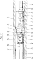
- FIG. 1 with a defective, non-accessible sewer pipeline for waste water is referred to, which is laid under the surface of the day between two sewer shafts, not shown.
- An inliner is to be drawn into the sewer pipeline 1, which is composed of short conduit pipes 2a, 3a, 2 or 2a, 3a, 20.
- the length of the line pipes 2a, 3a, 2 or 2a, 3a, 20 is dimensioned such that they can be introduced into the sewer pipe 1 one after the other through the shaft.
- the conduits 2 are each fitted with a socket end 3 on the outer jacket of the conduit 2a last introduced and connected to the conduit axis 4 to form a closed conduit which then forms the inliner in the conduit 1.
- the introduction of the line pipes 2 to the installation site on the already assembled pipe line of the inliner is carried out using a transport carriage 5 which can be moved on the channel bottom and onto which the line pipes 2 with the socket end 3 are placed in the installation direction.
- a cable pull is fastened to the transport carriage 5 with two pull cables 6 and 7 which are guided through the channel 1 on both sides and which are led out of the channel shafts via guide rollers (not shown) and pulled by cable winches (also not shown).
- the conduit 2 is supported on a vertical rear wall 8 of the transport carriage 5, to which a pivotable television camera 9 is also attached.
- Supply lines 10 are carried along with the transport carriage 5.
- the straightening carriage 11 is held in the respective installation position with radially directed hydraulic clamping cylinders 13.
- a boom 15 to 18 is provided for receiving the line pipes 2 brought up with the transport carriage 5, the axis of rotation 15 of which projects into the open sewer pipe line 1 and is connected to a rotary drive 14 is mounted on the straightening carriage 11 in the same axis as the pipe axis 4 of the inliner.
- an adjusting disk 16 is attached to the axis of rotation 15, on the outer edge of which conical guide pins 17 are arranged axially parallel to the axis of rotation 15, onto which the respectively introduced conduit 2 is pushed.
- Radially directed hydraulic tensioning cylinders 18 are also fastened to the adjusting disk 16, with which the line pipe 2 pushed over the guide pin 17 is held on the adjusting plate 16 so that the line pipe 2 can be rotated about the axis of rotation 15 with the rotary drive 14.
- the supply lines of the wagons 11 leading to the manhole are designated by 19.
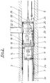
- a transport carriage 23 is used, as shown in FIG. 2, on the rear wall 24 of which an axis of rotation 25 is mounted.
- a hydraulically lockable tube holder 26 and a connection device 27 are fastened to it, with which the line tube 20 is connected to the inlet line 22 and the connection opening 21 is sealed.
- a television camera 9 is again provided to monitor the work processes.
Landscapes
- Engineering & Computer Science (AREA)
- General Engineering & Computer Science (AREA)
- Mechanical Engineering (AREA)
- Public Health (AREA)
- Health & Medical Sciences (AREA)
- Water Supply & Treatment (AREA)
- Chemical & Material Sciences (AREA)
- Combustion & Propulsion (AREA)
- Hydrology & Water Resources (AREA)
- Life Sciences & Earth Sciences (AREA)
- Sewage (AREA)
- Arrangement And Mounting Of Devices That Control Transmission Of Motive Force (AREA)
- Mechanical Operated Clutches (AREA)
- Supports For Pipes And Cables (AREA)
- Image Processing (AREA)
- Apparatus For Radiation Diagnosis (AREA)
Claims (6)
Priority Applications (1)
| Application Number | Priority Date | Filing Date | Title |
|---|---|---|---|
| AT89118686T ATE76920T1 (de) | 1988-10-15 | 1989-10-07 | Verfahren zum einbringen eines inliners in eine kanalrohrleitung und vorrichtungen zur durchfuehrung des verfahrens. |
Applications Claiming Priority (2)
| Application Number | Priority Date | Filing Date | Title |
|---|---|---|---|
| DE3835186 | 1988-10-15 | ||
| DE3835186A DE3835186C1 (fr) | 1988-10-15 | 1988-10-15 |
Publications (2)
| Publication Number | Publication Date |
|---|---|
| EP0365900A1 EP0365900A1 (fr) | 1990-05-02 |
| EP0365900B1 true EP0365900B1 (fr) | 1992-06-03 |
Family
ID=6365207
Family Applications (1)
| Application Number | Title | Priority Date | Filing Date |
|---|---|---|---|
| EP89118686A Expired - Lifetime EP0365900B1 (fr) | 1988-10-15 | 1989-10-07 | Procédé pour introduire un revêtement intérieure dans une canalisation et dispositif pour appliquer le procédé |
Country Status (6)
| Country | Link |
|---|---|
| EP (1) | EP0365900B1 (fr) |
| AT (1) | ATE76920T1 (fr) |
| DD (1) | DD288414A5 (fr) |
| DE (2) | DE3835186C1 (fr) |
| DK (1) | DK502489A (fr) |
| HU (1) | HU895314D0 (fr) |
Families Citing this family (5)
| Publication number | Priority date | Publication date | Assignee | Title |
|---|---|---|---|---|
| DE4019769A1 (de) * | 1990-06-21 | 1992-01-09 | Hemscheidt Maschf Hermann | Verfahren zum einbringen eines inliners in eine kanalrohrleitung und vorrichtung zur durchfuehrung des verfahrens |
| FI91992C (fi) * | 1992-04-07 | 1994-09-12 | Christer Storgaard | Sujutusputki |
| DE4439597C2 (de) * | 1994-11-05 | 1998-02-26 | Uhrig Kanaltechnik Gmbh | Verfahren zur Reparatur von Schadstellen unterirdischer Abwasserkanäle |
| DE29607323U1 (de) * | 1996-04-23 | 1997-05-28 | JT-Elektronik GmbH, 88131 Lindau | Transportvorrichtung für Kanalsanierungsmanschetten |
| CN117849164B (zh) * | 2024-01-24 | 2024-06-14 | 北京市燃气集团有限责任公司 | 一种管道漏磁检测系统 |
Family Cites Families (7)
| Publication number | Priority date | Publication date | Assignee | Title |
|---|---|---|---|---|
| US2525680A (en) * | 1946-04-15 | 1950-10-10 | Ingemarson Franc | Pipe aligning and spacing apparatus |
| FR1228386A (fr) * | 1958-03-22 | 1960-08-29 | Sulzer Ag | Chariot de support pour montage de tuyaux lourds |
| US3561320A (en) * | 1968-05-03 | 1971-02-09 | Crc Crose Int Inc | Method and means for aligning tube clamping mechanisms and the like |
| FR2263443A1 (en) * | 1974-03-04 | 1975-10-03 | Pont A Mousson | Hydraulic coupling mechanism for large diameter conduit - has inflatable collars which give bases for hydraulic cylinders |
| US4197908A (en) * | 1978-04-06 | 1980-04-15 | Underground Surveys Corporation | Apparatus for porting a side wall of a conduit from interiorly thereof |
| GB2079805B (en) * | 1980-07-05 | 1985-04-03 | Demco Ltd | Lining underground conduits |
| DE3413294C1 (de) * | 1984-04-09 | 1985-08-29 | Wiik & Höglund GmbH, 2400 Lübeck | Verfahren und Vorrichtung zum Einbau von Kunststoffrohrstuecken in Abwasserrohre |
-
1988
- 1988-10-15 DE DE3835186A patent/DE3835186C1/de not_active Expired - Fee Related
-
1989
- 1989-10-07 DE DE8989118686T patent/DE58901601D1/de not_active Expired - Fee Related
- 1989-10-07 AT AT89118686T patent/ATE76920T1/de not_active IP Right Cessation
- 1989-10-07 EP EP89118686A patent/EP0365900B1/fr not_active Expired - Lifetime
- 1989-10-10 DK DK502489A patent/DK502489A/da not_active Application Discontinuation
- 1989-10-11 DD DD89333507A patent/DD288414A5/de not_active IP Right Cessation
- 1989-10-13 HU HU895314A patent/HU895314D0/hu unknown
Also Published As
| Publication number | Publication date |
|---|---|
| HU895314D0 (en) | 1990-01-28 |
| DE3835186C1 (fr) | 1990-06-13 |
| DE58901601D1 (de) | 1992-07-09 |
| ATE76920T1 (de) | 1992-06-15 |
| EP0365900A1 (fr) | 1990-05-02 |
| DD288414A5 (de) | 1991-03-28 |
| DK502489A (da) | 1990-04-16 |
| DK502489D0 (da) | 1989-10-10 |
Similar Documents
| Publication | Publication Date | Title |
|---|---|---|
| DE3886449T2 (de) | Rohrleitungssystem. | |
| EP0158042B1 (fr) | Dispositif pour incorporer des tuyaux en matière plastique dans des égouts | |
| DE69930290T2 (de) | System, vorrichtung und verfahren zur installierung von steuerleitungen in einer erdbohrung | |
| EP2044356B1 (fr) | Dispositif et procédé d'intégration de conduites dans des systèmes de transport par canalisation | |
| DE3874216T2 (de) | Rohrleitungssystem. | |
| DE69707686T2 (de) | Ausgleichsinstrument | |
| DE69534139T2 (de) | Installation von Kabelkanälen | |
| DE2824915A1 (de) | Verfahren zum herstellen von beiderseits offenen erdbohrungen | |
| DE4238700C2 (de) | Vorrichtung zur Befestigung von Verbindungselementen an Rohrleitungen | |
| EP0365900B1 (fr) | Procédé pour introduire un revêtement intérieure dans une canalisation et dispositif pour appliquer le procédé | |
| EP0462527A1 (fr) | Procédé pour introduire et aligner des tuyaux de connexion d'un revêtement dans une canalisation et dispositif pour la mise en oeuvre du procédé | |
| EP0465892A1 (fr) | Méthode pour l'étanchéification d'un tuyau de branchement raccordé avec un tuyau d'égout et dispositif pour mise en oeuvre | |
| EP0978743A1 (fr) | Dispositif d'installation d'un chemisage à l'intérieur d'un tube non accessible | |
| DE19533949A1 (de) | Rohreinspannvorrichtung | |
| DE4038156A1 (de) | Vorrichtung und verfahren zum einziehen mindestens eines kabels oder hilfsseiles in ein kabelschutzrohr mittels eines unter druck stroemenden mediums | |
| EP0554416B1 (fr) | Procede et dispositif de renovation de canalisations d'immeuble raccordees a des conduits collecteurs inaccessibles d'eaux d'egouts | |
| EP0701492B1 (fr) | Procede d'installation d'un systeme de canalisations et dispositif de raccordement non liberable | |
| DE102017128404B4 (de) | Vorrichtung und Verfahren zur Inspektion und/oder Sanierung einer unterirdischen Rohrleitung | |
| EP0493862B1 (fr) | Méthode et dispositif pour la rénovation de pipe-lines | |
| DE10136967C2 (de) | Rohrzuführung | |
| EP1182392A2 (fr) | Appareil de perçage | |
| DE4344517C1 (de) | Verfahren und Anordnung zum Einziehen von Rohren ins Erdreich | |
| DE29624412U1 (de) | Vorrichtung zum Prüfen und/oder Bearbeiten eines rohrförmigen Werkstückes | |
| EP1106885A2 (fr) | Procédé et dispositif pour monter une garniture intérieure dans une structure en terre | |
| DE29908073U1 (de) | Gerät zur Überprüfung von Abzweigungen in einer Rohrleitung |
Legal Events
| Date | Code | Title | Description |
|---|---|---|---|
| PUAI | Public reference made under article 153(3) epc to a published international application that has entered the european phase |
Free format text: ORIGINAL CODE: 0009012 |
|
| AK | Designated contracting states |
Kind code of ref document: A1 Designated state(s): AT BE CH DE FR GB IT LI LU NL SE |
|
| 17P | Request for examination filed |
Effective date: 19900914 |
|
| 17Q | First examination report despatched |
Effective date: 19901203 |
|
| GRAA | (expected) grant |
Free format text: ORIGINAL CODE: 0009210 |
|
| AK | Designated contracting states |
Kind code of ref document: B1 Designated state(s): AT BE CH DE FR GB IT LI LU NL SE |
|
| PG25 | Lapsed in a contracting state [announced via postgrant information from national office to epo] |
Ref country code: IT Free format text: LAPSE BECAUSE OF FAILURE TO SUBMIT A TRANSLATION OF THE DESCRIPTION OR TO PAY THE FEE WITHIN THE PRE;WARNING: LAPSES OF ITALIAN PATENTS WITH EFFECTIVE DATE BEFORE 2007 MAY HAVE OCCURRED AT ANY TIME BEFORE 2007. THE CORRECT EFFECTIVE DATE MAY BE DIFFERENT FROM THE ONE RECORDED.SCRIBED TIME-LIMIT Effective date: 19920603 Ref country code: SE Effective date: 19920603 Ref country code: NL Effective date: 19920603 Ref country code: GB Effective date: 19920603 Ref country code: FR Effective date: 19920603 Ref country code: BE Effective date: 19920603 |
|
| REF | Corresponds to: |
Ref document number: 76920 Country of ref document: AT Date of ref document: 19920615 Kind code of ref document: T |
|
| REF | Corresponds to: |
Ref document number: 58901601 Country of ref document: DE Date of ref document: 19920709 |
|
| PG25 | Lapsed in a contracting state [announced via postgrant information from national office to epo] |
Ref country code: AT Effective date: 19921007 |
|
| EN | Fr: translation not filed | ||
| PG25 | Lapsed in a contracting state [announced via postgrant information from national office to epo] |
Ref country code: LI Effective date: 19921031 Ref country code: CH Effective date: 19921031 Ref country code: LU Free format text: LAPSE BECAUSE OF NON-PAYMENT OF DUE FEES Effective date: 19921031 |
|
| NLV1 | Nl: lapsed or annulled due to failure to fulfill the requirements of art. 29p and 29m of the patents act | ||
| GBV | Gb: ep patent (uk) treated as always having been void in accordance with gb section 77(7)/1977 [no translation filed] | ||
| PLBE | No opposition filed within time limit |
Free format text: ORIGINAL CODE: 0009261 |
|
| STAA | Information on the status of an ep patent application or granted ep patent |
Free format text: STATUS: NO OPPOSITION FILED WITHIN TIME LIMIT |
|
| 26N | No opposition filed | ||
| REG | Reference to a national code |
Ref country code: CH Ref legal event code: PL |
|
| PG25 | Lapsed in a contracting state [announced via postgrant information from national office to epo] |
Ref country code: DE Effective date: 19930701 |