EP0365958A2 - Méthode de compensation du décalage du point zéro dû à l'effet thermique sur des machines d'usinage, en particulier des tours et dispositif pour réaliser cette méthode - Google Patents
Méthode de compensation du décalage du point zéro dû à l'effet thermique sur des machines d'usinage, en particulier des tours et dispositif pour réaliser cette méthode Download PDFInfo
- Publication number
- EP0365958A2 EP0365958A2 EP89119143A EP89119143A EP0365958A2 EP 0365958 A2 EP0365958 A2 EP 0365958A2 EP 89119143 A EP89119143 A EP 89119143A EP 89119143 A EP89119143 A EP 89119143A EP 0365958 A2 EP0365958 A2 EP 0365958A2
- Authority
- EP
- European Patent Office
- Prior art keywords
- tool
- workpiece
- probe
- adjustment
- adjusted
- Prior art date
- Legal status (The legal status is an assumption and is not a legal conclusion. Google has not performed a legal analysis and makes no representation as to the accuracy of the status listed.)
- Withdrawn
Links
Images


Classifications
-
- G—PHYSICS
- G05—CONTROLLING; REGULATING
- G05B—CONTROL OR REGULATING SYSTEMS IN GENERAL; FUNCTIONAL ELEMENTS OF SUCH SYSTEMS; MONITORING OR TESTING ARRANGEMENTS FOR SUCH SYSTEMS OR ELEMENTS
- G05B19/00—Program-control systems
- G05B19/02—Program-control systems electric
- G05B19/18—Numerical control [NC], i.e. automatically operating machines, in particular machine tools, e.g. in a manufacturing environment, so as to execute positioning, movement or co-ordinated operations by means of program data in numerical form
- G05B19/401—Numerical control [NC], i.e. automatically operating machines, in particular machine tools, e.g. in a manufacturing environment, so as to execute positioning, movement or co-ordinated operations by means of program data in numerical form characterised by control arrangements for measuring, e.g. calibration and initialisation, measuring workpiece for machining purposes
- G05B19/4015—Numerical control [NC], i.e. automatically operating machines, in particular machine tools, e.g. in a manufacturing environment, so as to execute positioning, movement or co-ordinated operations by means of program data in numerical form characterised by control arrangements for measuring, e.g. calibration and initialisation, measuring workpiece for machining purposes going to a reference at the beginning of machine cycle, e.g. for calibration
-
- G—PHYSICS
- G05—CONTROLLING; REGULATING
- G05B—CONTROL OR REGULATING SYSTEMS IN GENERAL; FUNCTIONAL ELEMENTS OF SUCH SYSTEMS; MONITORING OR TESTING ARRANGEMENTS FOR SUCH SYSTEMS OR ELEMENTS
- G05B2219/00—Program-control systems
- G05B2219/30—Nc systems
- G05B2219/37—Measurements
- G05B2219/37025—Retract, swing out of the way, measuring device during normal machining for protection
-
- G—PHYSICS
- G05—CONTROLLING; REGULATING
- G05B—CONTROL OR REGULATING SYSTEMS IN GENERAL; FUNCTIONAL ELEMENTS OF SUCH SYSTEMS; MONITORING OR TESTING ARRANGEMENTS FOR SUCH SYSTEMS OR ELEMENTS
- G05B2219/00—Program-control systems
- G05B2219/30—Nc systems
- G05B2219/49—Nc machine tool, till multiple
- G05B2219/49219—Compensation temperature, thermal displacement
-
- G—PHYSICS
- G05—CONTROLLING; REGULATING
- G05B—CONTROL OR REGULATING SYSTEMS IN GENERAL; FUNCTIONAL ELEMENTS OF SUCH SYSTEMS; MONITORING OR TESTING ARRANGEMENTS FOR SUCH SYSTEMS OR ELEMENTS
- G05B2219/00—Program-control systems
- G05B2219/30—Nc systems
- G05B2219/50—Machine tool, machine tool null till machine tool work handling
- G05B2219/50252—Replace, change tool with tracer head, probe, feeler
-
- Y—GENERAL TAGGING OF NEW TECHNOLOGICAL DEVELOPMENTS; GENERAL TAGGING OF CROSS-SECTIONAL TECHNOLOGIES SPANNING OVER SEVERAL SECTIONS OF THE IPC; TECHNICAL SUBJECTS COVERED BY FORMER USPC CROSS-REFERENCE ART COLLECTIONS [XRACs] AND DIGESTS
- Y10—TECHNICAL SUBJECTS COVERED BY FORMER USPC
- Y10T—TECHNICAL SUBJECTS COVERED BY FORMER US CLASSIFICATION
- Y10T82/00—Turning
- Y10T82/25—Lathe
- Y10T82/2502—Lathe with program control
- Y10T82/2506—And tool turret
Definitions
- the invention relates to a method according to the preamble of patent claim 1.
- Machine tools are subject to thermal expansion of the machine system. This results in migrations of the zero points to each other, e.g. B. the spindle (workpiece), a tool measuring device and a tool carrier. The sum of the movements leads to incorrect positions of the tool relative to the workpiece. This results in position errors on the order of magnitude of up to about 100 ⁇ m and rarely above it.
- a method and an apparatus for tool touch test is known.
- the need for a reference ring (reference surface) to be arranged on the chuck should be eliminated by means of a reference column device attached directly to a lathe.
- a reference column belonging to the device should be arranged in a calibrated position and resiliently on the machine and in relation to the workpiece.
- the reference column should also be able to be set in ultrasonic vibrations.
- An accelerometer arranged on the turret of the lathe in question is intended to react to the reference column vibrations when a tool as a probe is brought into contact with the reference column.
- the output signal of the accelerometer is then to be transmitted from the turret head through a rotary coupler, processed and then fed to a numerical control unit and used either for calibrating or teaching parts during machining.
- the present known case seeks to improve the measurement of the so-called “measurement cuts” by measuring the “measurement cuts” in all positions only with the appropriate tool; however, the intended improvement in workpiece measurement is again based on the thesis of a practically existing fixed, rigid zero point; consequently, corrections to the tool cutting edge position would again involve the error of thermal migration. In the present known case, it is therefore not possible to do without “measurement cuts”.
- the invention has for its object to eliminate the disadvantages presented to known and to create an extremely simplified method for compensating for the thermally induced zero offsets that works practically without manual intervention in the workflow.
- the invention is based on the establishment of a relative correspondence between the zero points of the spindle, the tool measuring device and the tool carrier. In other words, the relevant mechanical migration amounts are measured and corrected.
- a self-regulating machining process can thus be represented, which does not require any subsequent correction by the worker concerned for a manufacturing tolerance range of ⁇ 30 ⁇ m.
- the workpiece to be machined or already machined thus represents practically “the masterpiece”. It is therefore advantageously possible, even before the actual workpiece machining, to produce a component wall that is thermally induced determinations (ambient conditions) to determine and correct the zero point shift. A measurement cut is therefore not necessary.
- the method according to the invention can be practiced or repeated as part of the ongoing machining process, as desired. It is therefore also possible to continuously take into account the temperature influences which occur as a result of the workpiece machining and which lead to a zero point shift.
- the compensation can be carried out without manual intervention, especially since the replacement of "tool in tool probe” - or vice versa, takes place automatically on the machine side.
- the invention is concerned with the optimization of the machining of, in particular, rotationally symmetrical components or component structures; in the case of the rotationally symmetrical structures it can be, for. B. the relevant outer or inner contour or z. B. act a rotationally symmetrical recess.
- the component to be treated could be contoured in principle as desired (external dimensions) if it was e.g. B. is only about the machining of a cylindrical inner recess in this component.
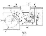
- Fig. 1 it is z. B. the manufacture of a cylindrical component 1 with a coaxial cylindrical recess 1 '. It is assumed here that the component 1 is seated absolutely non-rotatably on a spindle 2 of a lathe in question via clamping devices (not shown). The axis of rotation of the spindle 2 coinciding with the axis of the component 1 is designated by A.
- a tool carrier belonging to the lathe is also designated by 3, a tool measuring device by 4 and a machine control system, schematically represented as a block, by 5.
- the tool carrier 3 with assignment of a carriage 9 along an anchored to a machine bed 10 track 11 (arrow B) to, in the way of appropriate movement, z. B. G, the memory 8, the required tool, for. B. 6, and then - as a result of a corresponding return movement (arrow R) the processing purpose or the position required for this.
- Basic problem of the present invention is that e.g. B. is subjected to a lathe of the type schematically indicated in FIGS. 1 and 3 thermally induced expansions of the machine system, which in turn leads to migration of the relevant zero points P1 (spindle 2 and component 1), P2 (tool carrier 3) and P3 (measuring device 4th ) to lead. It is u. a. Essential to the invention that the measuring device 4 in question, together with an associated tool probe T2, is also included in the compensation method explained in detail below.
- D1 and D2 identify in FIG. 1 e.g. B.
- the relative thermal migration is represented roughly schematically in FIG. 2, on the one hand, by x, in terms of tool 6 and cutting edge position to workpiece (component 1). y in FIG.
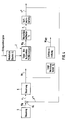
- a workpiece probe T 1 in the tool holder 3 automatically is exchanged; the workpiece probe T1 is in the target default position (also called old default value W0 in FIG. 4); this workpiece probe T1 is in consideration of the actual position of the component 1, here z. B. by mechanical contact of the relevant inner wall of an already existing or pre-machined recess 1 'to the actually existing zero point position (P1) adjusted (calibrated), namely according to the new default value W1 of the tool holder 3 - see also Fig.
- Direction of arrow R (see also Fig. 2) against the tool probe T2 move (mechanical contact).
- the adjustment processes mentioned can be repeated any number of times, possibly two or more times; these are usually fine adjustment processes of the relevant buttons T 1, T 2 within the range of the position errors specified at the outset, for example in ⁇ m ranges up to 100 ⁇ m and possibly also above them.
- electromechanical gearbox configurations can be used, which can be integrated both in the tool carrier 3 and in the measuring device 4 or in the arm 9 (Fig. 3), which contains the tool probe T2.
- this arm 12 z from its rest position. B. be pivoted into such an operating position in which the tool probe T2 z. B. parallel, above the component 1 (workpiece) together with the spindle 2, so that it can be contacted by the workpiece probe T 1 according to arrow R (direction of movement of the carrier 3).
- the workpiece measuring probe T1 in the tool memory 8 (FIG. 3) into a tool 6 or 6 'or 6 ⁇ and immediately automatically replaced (arrows B or G or F) as already discussed in the introduction.
- the exchanged tool 6, 6 ', 6 ⁇ ... is then moved according to the direction of movement R of the carrier 3 against the tool probe T2 which is in the operating position, so that the tool exchanged for T1 via the thermally induced position deviations (disturbance variable Z - Fig. 4) Adjust the corrected position Ww z of the tool probe T2.
- the tool store 8 contains, if necessary, one or more call-up and suitable or prepared workpiece probes T 1 and tools 6, 6 ', etc. which have already been mentioned.
- the tool measuring device 4 is in signal-transmitting connection (signal flow S) with the machine controller 5.
- 4 is basically a measured value generator as a function from received setpoint specifications (old default value T2) on the one hand and as a function received actual positions (actual values) on the other side (new default value W1).
- the schematic signal flow St in Fig. 1 denotes an electrohydraulic connecting chain between the machine control 5 and tool carrier 3, which is designed so that u. a. Electrical signals for the carrier adjustment from FIG. 5 can be converted into a hydraulic adjustment of the tool carrier 3 via suitable feedback elements. St also embodies schematically the feedback carrier 3 / machine control 5 (cumput supported) to provide the "old" or "new" default positions W0 or W1 (see also Fig. 4).
- the sequence of the compensation method according to the invention for. B. during ongoing processing as follows: - Automatic replacement of the workpiece probe T1 in the tool holder 3; - Calibration or adjustment of the workpiece probe T1 by mechanical contacting of the workpiece (component 1), and thus in relation to its actual zero point deviation; - Zero point adjustment of the tool measuring device 4 via the previously adjusted workpiece probe T 1 with respect to the thermal position deviation registered by the latter; - Automatic replacement of the workpiece probe T1 on the tool carrier 3 in the tool 6; - Adjusting the tool 6 on the tool measuring device 4 corrected for thermally induced position deviations; - Continuation of the programmed processing sequence.
- FIG. 5 One way of scanning and measuring the component 1 is shown using the example of FIG. 5 using a mechanical-electrical workpiece measuring probe T 1.
- a workpiece probe T 1 can be easily clamped into the tool carrier 3 of the lathe according to FIGS. 1 and 3 and can be connected to the tool measuring device 4 as a measured value generator by cable (telemetric) or by cable.
- Switching of the probe system is preferred, which can also be used automatically in automatic tool changing devices.
- the switching signal is generated by mechanical deflection of the workpiece probe T1, as shown in Fig. 5 by the pivot arrow F, ie the probe T1 bends by a certain angle when probing the component 1.
- the deflection of the probe or the deflection F of the ball 9 can be used for this at the tip of the workpiece probe T1 depending on the preload and depending on the length and the modulus of elasticity of the probe T 1 are corrected by offsetting the correction value with the measurement result.
- the tool probe T2 (Fig. 1) can be constructed in the same or similar manner.
- the method according to the invention can be applied at any desired point in time during processing without, for. B having to convert or retrofit calibration workpieces on the spindle, both for single-part production and for series production in order to comply with very low tolerances.
- the invention therefore represents an inexpensive and flexible method in order to meet the highest quality requirements and to increase machine utilization.
- a strong reduction in the set-up time is another decisive advantage of the method according to the invention.
Landscapes
- Engineering & Computer Science (AREA)
- Human Computer Interaction (AREA)
- Manufacturing & Machinery (AREA)
- Physics & Mathematics (AREA)
- General Physics & Mathematics (AREA)
- Automation & Control Theory (AREA)
- Automatic Control Of Machine Tools (AREA)
- Machine Tool Sensing Apparatuses (AREA)
Applications Claiming Priority (2)
| Application Number | Priority Date | Filing Date | Title |
|---|---|---|---|
| DE3836263 | 1988-10-25 | ||
| DE3836263A DE3836263C1 (fr) | 1988-10-25 | 1988-10-25 |
Publications (2)
| Publication Number | Publication Date |
|---|---|
| EP0365958A2 true EP0365958A2 (fr) | 1990-05-02 |
| EP0365958A3 EP0365958A3 (fr) | 1990-10-31 |
Family
ID=6365844
Family Applications (1)
| Application Number | Title | Priority Date | Filing Date |
|---|---|---|---|
| EP19890119143 Withdrawn EP0365958A3 (fr) | 1988-10-25 | 1989-10-14 | Méthode de compensation du décalage du point zéro dû à l'effet thermique sur des machines d'usinage, en particulier des tours et dispositif pour réaliser cette méthode |
Country Status (4)
| Country | Link |
|---|---|
| US (1) | US5095788A (fr) |
| EP (1) | EP0365958A3 (fr) |
| JP (1) | JPH02167651A (fr) |
| DE (1) | DE3836263C1 (fr) |
Cited By (3)
| Publication number | Priority date | Publication date | Assignee | Title |
|---|---|---|---|---|
| FR2684912A1 (fr) * | 1991-12-11 | 1993-06-18 | Snecma | Procede de determination d'une trajectoire de robot. |
| EP0545658A3 (en) * | 1991-12-02 | 1993-07-14 | General Electric Company | Automated maintenance system for computer numerically controlled machines |
| EP0602678A3 (fr) * | 1992-12-17 | 1995-12-06 | Bernd Eisenbach | Procédé et dispositif pour usiner des encadrements soudés ensemble de profilés faits en matière plastique ou en métal. |
Families Citing this family (22)
| Publication number | Priority date | Publication date | Assignee | Title |
|---|---|---|---|---|
| JP2578241B2 (ja) * | 1990-04-05 | 1997-02-05 | 松下電器産業株式会社 | 自動プログラム作成装置 |
| US5387061A (en) * | 1990-12-14 | 1995-02-07 | The United States Of America As Represented By The United States Department Of Energy | Parameter monitoring compensation system and method |
| EP0512956B1 (fr) * | 1991-05-07 | 1994-09-07 | Voumard Machines Co. S.A. | Rectifieuse à commande numérique |
| JPH052214U (ja) * | 1991-06-24 | 1993-01-14 | 横河電機株式会社 | モ―タの制御システム |
| US5375066A (en) * | 1993-03-01 | 1994-12-20 | The United States Of America As Represented By The Secretary Of Commerce | Apparatus and methods for implementing error correction in real time for machine tools with encoder-type position feedback |
| US5373222A (en) * | 1993-03-17 | 1994-12-13 | General Electric Company | Datuming device for measuring displacements not parallel with a displacement probe's line of travel |
| JPH07266193A (ja) * | 1994-03-30 | 1995-10-17 | Toshiba Mach Co Ltd | 熱変位補正装置 |
| GB9514321D0 (en) * | 1995-07-13 | 1995-09-13 | Renishaw Plc | Laser measuring apparatus |
| US6225771B1 (en) * | 1999-12-01 | 2001-05-01 | General Electric Company | Probe chord error compensation |
| JP4351379B2 (ja) * | 2000-11-02 | 2009-10-28 | 村田機械株式会社 | 工作機械 |
| DE102004033119A1 (de) * | 2004-07-08 | 2006-02-02 | Siemens Ag | Regelungsverfahren für eine Werkzeugmaschine mit numerischer Steuerung, Werkzeugmaschine, sowie Bearbeitungskopf und Werkzeugaufnahme |
| DE102005020034A1 (de) * | 2005-04-29 | 2006-11-02 | Vollmer Werke Maschinenfabrik Gmbh | Vorrichtung zum Bearbeiten und Vermessen von mit Schneidzähnen versehenen Werkstücken |
| US7957834B2 (en) * | 2006-05-31 | 2011-06-07 | Panasonic Corporation | Method for calculating rotation center point and axis of rotation, method for generating program, method for moving manipulator and positioning device, and robotic system |
| DE102010054393A1 (de) | 2010-12-07 | 2012-06-14 | Chiron-Werke Gmbh & Co. Kg | Verfahren zur Bestimmung der Position eines Werkzeuges |
| US9026242B2 (en) | 2011-05-19 | 2015-05-05 | Taktia Llc | Automatically guided tools |
| US10556356B2 (en) | 2012-04-26 | 2020-02-11 | Sharper Tools, Inc. | Systems and methods for performing a task on a material, or locating the position of a device relative to the surface of the material |
| WO2014076454A1 (fr) | 2012-11-14 | 2014-05-22 | Renishaw Plc | Procédé et appareil de mesure d'une pièce avec une machine-outil |
| US10955238B1 (en) * | 2013-03-15 | 2021-03-23 | Kerr Machine Co. | In-process automatic recalibration |
| US20140363316A1 (en) * | 2013-06-11 | 2014-12-11 | Caterpillar, Inc. | Remanufactured Hydraulic Device, Housing And Remanufacturing Method |
| EP3294503B1 (fr) | 2015-05-13 | 2020-01-29 | Shaper Tools, Inc. | Systèmes, procédés et appareil pour outils guidés |
| CN109643098B (zh) | 2016-08-19 | 2022-06-03 | 整形工具股份有限公司 | 一种用于跟踪钻机的使用的系统、方法及介质 |
| CN117518982B (zh) * | 2023-11-14 | 2024-04-19 | 盐城市恒帅机械有限公司 | 一种提高机床加工精度的方法及系统 |
Family Cites Families (8)
| Publication number | Priority date | Publication date | Assignee | Title |
|---|---|---|---|---|
| JPS6022721B2 (ja) * | 1978-07-06 | 1985-06-04 | 豊田工機株式会社 | 接触検出用ヘツドを用いた芯出し測定装置 |
| JPS58206364A (ja) * | 1982-05-24 | 1983-12-01 | Toshiba Mach Co Ltd | 工作機械 |
| US4636960A (en) * | 1982-09-16 | 1987-01-13 | Renishaw Electrical Limited | Method of operating a machine tool with a sensing probe in order to gather positional data for the calculation of tool offset parameters |
| JPS6127649U (ja) * | 1984-07-26 | 1986-02-19 | 宣行 杉村 | Nc旋盤のねじ用タツチセンサ |
| US4562392A (en) * | 1984-08-29 | 1985-12-31 | General Electric Company | Stylus type touch probe system |
| US4554495A (en) * | 1984-08-29 | 1985-11-19 | Ormand R. Austin | Datum reference for tool touch probe system |
| US4653360A (en) * | 1985-05-07 | 1987-03-31 | The Cross Company | CNC turning machine |
| DE3603316C2 (de) * | 1986-02-04 | 1995-01-26 | Index Werke Kg Hahn & Tessky | Einrichtung zum Einstellen des Arbeitspunkts eines Werkzeugs in einer CNC-Werkzeugmaschine |
-
1988
- 1988-10-25 DE DE3836263A patent/DE3836263C1/de not_active Expired - Lifetime
-
1989
- 1989-10-14 EP EP19890119143 patent/EP0365958A3/fr not_active Withdrawn
- 1989-10-25 JP JP1276207A patent/JPH02167651A/ja active Pending
- 1989-10-25 US US07/427,331 patent/US5095788A/en not_active Expired - Fee Related
Cited By (3)
| Publication number | Priority date | Publication date | Assignee | Title |
|---|---|---|---|---|
| EP0545658A3 (en) * | 1991-12-02 | 1993-07-14 | General Electric Company | Automated maintenance system for computer numerically controlled machines |
| FR2684912A1 (fr) * | 1991-12-11 | 1993-06-18 | Snecma | Procede de determination d'une trajectoire de robot. |
| EP0602678A3 (fr) * | 1992-12-17 | 1995-12-06 | Bernd Eisenbach | Procédé et dispositif pour usiner des encadrements soudés ensemble de profilés faits en matière plastique ou en métal. |
Also Published As
| Publication number | Publication date |
|---|---|
| DE3836263C1 (fr) | 1990-06-07 |
| JPH02167651A (ja) | 1990-06-28 |
| EP0365958A3 (fr) | 1990-10-31 |
| US5095788A (en) | 1992-03-17 |
Similar Documents
| Publication | Publication Date | Title |
|---|---|---|
| EP0365958A2 (fr) | Méthode de compensation du décalage du point zéro dû à l'effet thermique sur des machines d'usinage, en particulier des tours et dispositif pour réaliser cette méthode | |
| DE69221088T2 (de) | Werkzeugspritzeausgleichung für Hardware-Verlagerung und Neigung | |
| EP0779849B1 (fr) | Procede et dispositif permettant de detecter et de corriger des defauts de jointure et des defauts dus a l'usure de l'outil lors d'operations de percage de precision | |
| DE69230137T2 (de) | Vorschubvorrichtung mit einer schraube und mit einer feineinstellung | |
| DE4401496C3 (de) | Werkzeugschneiden-Verstelleinrichtung zum Bearbeiten von runden, unrunden und/oder nicht zylinderförmigen Innen- und/oder Außenkonturen | |
| EP2040881B1 (fr) | Procédé d'usinage combiné par perçage de précision et rodage ainsi qu'installation d'usinage pour la mise en oeuvre du procédé | |
| DE4004237C2 (fr) | ||
| DE69718520T2 (de) | Verfahren zum Schleifen von Verbundwerkstücken | |
| DE102005007038B4 (de) | Werkstückspindelstock | |
| EP1839010B9 (fr) | Procede de determination d'une coordonnee spatiale d'un point de mesure sur un objet de mesure et instrument de mesure de coordonnees correspondant | |
| DE19858154A1 (de) | Verfahren und Einrichtung zur Kalibrierung von bewegbaren Vorrichtungen mit mindestens einem teilweise unbestimmten Geometrieparameter | |
| DE60107920T2 (de) | Werkzeugmaschine mit Werkzeugspositionskontrolle | |
| EP0439425A1 (fr) | Dispositif pour la fabrication d'une lentille ophtalmique avec, en particulier, des surfaces asphériques | |
| DE10345993B4 (de) | Verfahren und Vorrichtung zum Messen und zum Feinstellen eines Werkzeuges in einem Werkzeughalter und Verfahren zum Messen einer Bearbeitungskraft | |
| DE4030994A1 (de) | Pruefeinrichtung fuer rotationssymmetrische werkstuecke | |
| DE10030087B4 (de) | Verfahren und Vorrichtung zum Vermessen und Bearbeiten von Werkstücken | |
| WO2009037165A1 (fr) | Procédé de détermination d'un changement de position d'origine thermique d'une section d'une machine-outil | |
| WO2009030585A1 (fr) | Machine-outil | |
| WO2006005700A1 (fr) | Procede de reglage conçu pour une machine-outil a commande numerique | |
| EP3611584B1 (fr) | Procédé de fonctionnement d'un tour avec une lunette | |
| EP0999004A2 (fr) | Mandrin pour une machine-outil | |
| DE19514054B4 (de) | Mehrfachspindel-Werkzeugmaschine, sowie Verfahren zum Kompensieren von Positionsänderungen einer Werkstück-Trägerspindel | |
| DE9422389U1 (de) | Werkzeugschneiden-Verstelleinrichtung zum hochgenauen Bearbeiten von runden, unrunden und/oder nicht zylinderförmigen Innen- und/oder Außenkonturen | |
| DE102012103548A1 (de) | Verfahren und Vorrichtung zum Ausrichten eines Werkzeugs sowie Bearbeitungsstation und Messeinrichtung | |
| DE3902854A1 (de) | Fertigungseinrichtung mit wechselpaletten |
Legal Events
| Date | Code | Title | Description |
|---|---|---|---|
| PUAI | Public reference made under article 153(3) epc to a published international application that has entered the european phase |
Free format text: ORIGINAL CODE: 0009012 |
|
| AK | Designated contracting states |
Kind code of ref document: A2 Designated state(s): AT CH DE FR GB IT LI NL SE |
|
| PUAL | Search report despatched |
Free format text: ORIGINAL CODE: 0009013 |
|
| AK | Designated contracting states |
Kind code of ref document: A3 Designated state(s): AT CH DE FR GB IT LI NL SE |
|
| 17P | Request for examination filed |
Effective date: 19901025 |
|
| 17Q | First examination report despatched |
Effective date: 19940124 |
|
| GRAG | Despatch of communication of intention to grant |
Free format text: ORIGINAL CODE: EPIDOS AGRA |
|
| GRAH | Despatch of communication of intention to grant a patent |
Free format text: ORIGINAL CODE: EPIDOS IGRA |
|
| RBV | Designated contracting states (corrected) |
Designated state(s): AT CH FR GB IT LI NL SE |
|
| REG | Reference to a national code |
Ref country code: DE Ref legal event code: 8566 |
|
| STAA | Information on the status of an ep patent application or granted ep patent |
Free format text: STATUS: THE APPLICATION HAS BEEN WITHDRAWN |
|
| 18W | Application withdrawn |
Withdrawal date: 19970311 |