EP0366224B1 - Richtige-Amplituden-Neigungsausschlagkorrektur - Google Patents
Richtige-Amplituden-Neigungsausschlagkorrektur Download PDFInfo
- Publication number
- EP0366224B1 EP0366224B1 EP89306237A EP89306237A EP0366224B1 EP 0366224 B1 EP0366224 B1 EP 0366224B1 EP 89306237 A EP89306237 A EP 89306237A EP 89306237 A EP89306237 A EP 89306237A EP 0366224 B1 EP0366224 B1 EP 0366224B1
- Authority
- EP
- European Patent Office
- Prior art keywords
- seismic
- corrected
- moveout
- dip
- synthetic dataset
- Prior art date
- Legal status (The legal status is an assumption and is not a legal conclusion. Google has not performed a legal analysis and makes no representation as to the accuracy of the status listed.)
- Expired - Lifetime
Links
- 238000012937 correction Methods 0.000 title claims description 41
- 238000000034 method Methods 0.000 claims description 69
- 238000007598 dipping method Methods 0.000 claims description 20
- 238000013508 migration Methods 0.000 claims description 14
- 230000005012 migration Effects 0.000 claims description 14
- 238000002310 reflectometry Methods 0.000 claims description 14
- 230000003595 spectral effect Effects 0.000 claims description 6
- 230000003213 activating effect Effects 0.000 claims description 3
- 230000004913 activation Effects 0.000 claims description 3
- 230000036962 time dependent Effects 0.000 claims description 3
- 230000008569 process Effects 0.000 description 17
- 238000012545 processing Methods 0.000 description 7
- 238000003384 imaging method Methods 0.000 description 6
- 239000013598 vector Substances 0.000 description 6
- 238000010586 diagram Methods 0.000 description 5
- 238000013459 approach Methods 0.000 description 3
- 238000013507 mapping Methods 0.000 description 3
- 230000008901 benefit Effects 0.000 description 2
- 230000014509 gene expression Effects 0.000 description 2
- 238000001228 spectrum Methods 0.000 description 2
- 238000010561 standard procedure Methods 0.000 description 2
- 230000005526 G1 to G0 transition Effects 0.000 description 1
- 238000009933 burial Methods 0.000 description 1
- 230000008859 change Effects 0.000 description 1
- 230000001419 dependent effect Effects 0.000 description 1
- 238000009795 derivation Methods 0.000 description 1
- 238000013461 design Methods 0.000 description 1
- 230000001066 destructive effect Effects 0.000 description 1
- 230000000694 effects Effects 0.000 description 1
- 238000011156 evaluation Methods 0.000 description 1
- 230000009467 reduction Effects 0.000 description 1
- 238000005070 sampling Methods 0.000 description 1
- 239000007787 solid Substances 0.000 description 1
- 230000002123 temporal effect Effects 0.000 description 1
- 230000009466 transformation Effects 0.000 description 1
- 230000001131 transforming effect Effects 0.000 description 1
Images

Classifications
-
- G—PHYSICS
- G01—MEASURING; TESTING
- G01V—GEOPHYSICS; GRAVITATIONAL MEASUREMENTS; DETECTING MASSES OR OBJECTS; TAGS
- G01V1/00—Seismology; Seismic or acoustic prospecting or detecting
- G01V1/28—Processing seismic data, e.g. for interpretation or for event detection
- G01V1/36—Effecting static or dynamic corrections on records, e.g. correcting spread; Correlating seismic signals; Eliminating effects of unwanted energy
- G01V1/362—Effecting static or dynamic corrections; Stacking
-
- G—PHYSICS
- G01—MEASURING; TESTING
- G01V—GEOPHYSICS; GRAVITATIONAL MEASUREMENTS; DETECTING MASSES OR OBJECTS; TAGS
- G01V1/00—Seismology; Seismic or acoustic prospecting or detecting
- G01V1/28—Processing seismic data, e.g. for interpretation or for event detection
- G01V1/282—Application of seismic models, synthetic seismograms
-
- G—PHYSICS
- G01—MEASURING; TESTING
- G01V—GEOPHYSICS; GRAVITATIONAL MEASUREMENTS; DETECTING MASSES OR OBJECTS; TAGS
- G01V2210/00—Details of seismic processing or analysis
- G01V2210/50—Corrections or adjustments related to wave propagation
- G01V2210/52—Move-out correction
- G01V2210/522—Dip move-out [DMO]
-
- G—PHYSICS
- G01—MEASURING; TESTING
- G01V—GEOPHYSICS; GRAVITATIONAL MEASUREMENTS; DETECTING MASSES OR OBJECTS; TAGS
- G01V2210/00—Details of seismic processing or analysis
- G01V2210/60—Analysis
- G01V2210/61—Analysis by combining or comparing a seismic data set with other data
- G01V2210/614—Synthetically generated data
Definitions
- This invention deals with an improved method and apparatus for three-dimensional seismic imaging by which seismic amplitudes are preserved, so that the amplitudes on the final seismic image are proportional to the reflectivity of the earth, regardless of the geologic dip, depth of burial, or seismic recording geometry.
- the technique is easily specialized to two-dimensional DM0, in the case where the shot-receiver axis lies along the direction of survey.
- CDP Common-depth-point stacking
- NM0 normal moveout
- DMO dip moveout
- the present invention provides a practical method and apparatus for transforming a set of areally-distributed seismic field traces into an image whose amplitudes are directly proportional to the earth's reflectivity.
- the present invention provides apparatus for carrying out true-amplitude dip moveout on seismic data, characterised by means for generating a set of correction filters for application to data from seismic surveys and means for applying the correction filters during dip movement correction operations on data from seismic surveys, wherein the means for generating the set of correction filters comprises means for selecting a reflectivity and dip for a theoretical dipping layer in three dimensions; means for generating a synthetic dataset corresponding to reflection from the theoretical dipping layer using a known deconvolved source wavelet and a conventional three dimensional scalar wave equation; means for correcting the synthetic dataset for spherical divergence to provide a spherical divergence corrected synthetic dataset; means for correcting the spherical divergence corrected synthetic dataset for normal moveout to provide a normal moveout corrected synthetic dataset; means for correcting the normal moveout corrected synthetic dataset for dip moveout using an extra degree of freedom in the dip moveout equation to provide a corrected synthetic dataset; means for performing zero-offset migration on the corrected synthetic dataset to provide a migrated seismic image;
- One preferred form of apparatus also comprises means for energizing one or more seismic energy sources located in a survey area in order to generate seismic traces at one or more seismic receivers located in the survey area; means for treating each seismic signal to produce a wavelet of substantially constant spectral value over a bandwidth range; means for correcting each treated seismic signal for spherical divergence to provide a spherical divergence-corrected seismic signal; means for correcting each spherical divergence-corrected seismic signal for normal moveout to provide a normal moveout-corrected seismic signal; means for correcting each normal moveout-corrected seismic signal for dip moveout using the correction filters to provide a corrected seismic signal; and means for performing zero-offset migration on the corrected seismic signal.
- the invention also includes the methods per se .
- An improved DM0 process which consists of a calibration method for designing a set of filters that correct the seismic amplitudes so as to preserve true-amplitude imaging.
- These filters can be designed and applied in any known implementation of DM0.
- the filters can be applied in three-dimensional DM0 or specialized to two-dimensional DM0. Special particularly convenient forms of the filters result when the spatial sampling of the input traces is reasonably uniform.
- the modified DM0 process produces output traces in designated output-cell locations.
- the output traces in all cells may be displayed as a zero-offset three-dimensional unmigrated image of the earth.
- Application of a subsequent 3D zero-offset migration yields traces which may be displayed as a three-dimensional image proportional to the reflectivity of the earth.
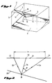
- Figure 1 is an isometric view of the earth with a dipping reflector, showing the relationship between the raypaths for a finite-offset source-receiver pair and a zero-offset source-receiver pair reflecting from the same point.
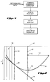
- Figure 2 is a section view in the plane containing the source, receiver, and reflection point from Figure 1.
- Figure 3 is a flow diagram of the amplitude-preserving seismic imaging system of the present invention.
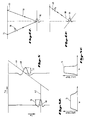
- Figure 4 is a time section corresponding to Figure 2, showing how the amplitudes on an input trace are filtered and mapped to produce an output trace in the summation method of DM0.
- Figure 5 is an illustration of a convention by which the amplitude of a seismic image is related to the earth's reflectivity.
- Figure 6 is a raypath diagram illustrating the effect of reflection obliquity on the bandwidth of the final wavelet in the seismic image.
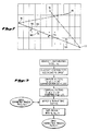
- Figure 7 is a plan view of a 3D seismic survey, showing the relationship between the recording geometry of Figure 1 and the output cells into which DM0 puts traces.
- Figure 8 is a flow diagram of an embodiment of the process for obtaining the correction filters of the present invention.
- Figure 9 is a flow diagram of an implementation of the embodiment of DM0 process described in this invention.
- Boldface quantities (e.g. y) indicate two-dimensional vectors along the earth's surface.
- FIG. 1 a plan view of a 3D seismic survey is shown.
- the seismic energy emanates from source 2 and is received at receiver 4.
- the trace recorded for this source and receiver is conventionally displayed at the source-receiver midpoint position 6, whose Cartesian coordinate vector is denoted by y.
- the energy bounces off the reflector 8 at the reflection point 10, with raypath 12 from source 2 to reflection point 10 and raypath 14 from reflection point 10 to receiver 4.
- the purpose of three-dimensional (3D) DMO is to create an equivalent trace corresponding to the zero-offset raypath 16 and to position that trace at surface location 18, whose Cartesian coordinate is denoted by x i .
- Figure 2 is a section view of raypaths for a dipping reflector displayed in the plane containing the source 22, receiver 24 and reflection point 30.
- the source-receiver offset, the distance between source 22 and receiver 24, has the value 2h.
- Figure 3 shows a processing sequence for producing a true-amplitude image of any reflector, such as the one illustrated in figures 1 and 2.
- the input data has been previously deconvolved to produce a wavelet of approximately constant spectral amplitude over a bandwidth range.
- This step which does not form part the present invention, can be performed by any of a number of standard techniques, with which those skilled in the art are familiar.
- the imaging sequence, shown in Figure 3 is spherical-divergence correction, normal-moveout (NMO) correction, 3D DMO, and 3D zero-offset migration. It is generally understood that the data corresponding to different offsets is stacked together at some stage after the NMO has been performed to improve the signal to noise ratio.
- the spherical-divergence correction in simplest form consists of multiplying each deconvolved trace P(y,t h ) by t h , to yield P s (y,t h ) but the present invention is not limited to this particular form of correction.
- the NMO correction consists of mapping P s (y,t h ) to post-NMO time t 0 by the well-known relationship: where v is the rms velocity.
- the migration can be done by any of a number of well-known standard techniques.
- DMO can be equivalently applied to input traces arranged into various sets: common-offset sections, common-shot records, and single-trace sets. For 3D implementations, it is often more convenient to not apply DMO to common-offset sections or common-shot records, but to process each individual input trace in essentially whatever order it appears on the magnetic tape. The improved method of DMO described here can be applied to any of these input-trace organizations.
- Some DMO implementations produce data in which all offsets have been summed together, producing a stack section ready to go immediately into the zero-offset migration algorithm.
- Other DMO implementations produce output traces which are arranged into various sets, to be stacked together after some subsequent processing. In particular, it is useful to keep the DMO outputs separated according to their offsets, so as to allow a velocity analysis after DMO has been applied to the data. After this velocity analysis has been performed, the traces can be corrected for residual NMO errors (occurring in the NMO step that preceded DMO) prior to being stacked and migrated.
- the improved DMO algorithm presented here can be used to produce output traces which are offset-separated or which are already stacked over offset.
- FIG. 4 shows how the Deregowski and Rocca summation method of DMO is carried out.
- the input seismic trace is shown schematically as the vertical line 40, which is positioned at the source-receiver midpoint position 42, whose Cartesian coordinate is y.
- the individual digitally-recorded amplitudes on the seismic trace are at the discrete time positions indicated by the solid dots, such as 44.
- the DMO process generates a plurality of output traces, such as 46 and 50. This is in keeping with the fact that the DMO process makes no assumption about the angle of dip of the seismic data which governs the location of the zero-offset output trace and therefore must allow each input trace to contribute to a number of output traces within a DMO aperture distance 52. This aperture is generally determined by the maximum physically-allowable dip.
- the Deregowski and Rocca summation method of DMO consists of convolving a time-variant filter with the input trace 40 and then mapping the resultant amplitude along the DMO trajectory 56.
- Derivation of a suitable DMO trajectory is taught by Deregowski and Rocca in the publication referenced above, and is familiar to those skilled in the art.
- the present invention provides an improved time variant filter, which is hereinafter described. For example the set of points 58 is multiplied with the elements of the filter, and the sum of these products is mapped to the time sample 60 on the output trace 46. This process is repeated for every other output trace, such as 50, within the DMO aperture distance 52 on either side of the midpoint 42.
- the elements of the time-variant filter are then applied to a new set of points displaced one time sample deeper than points 58, and the entire process is repeated until all time samples on the input trace 40 have been exhausted. The process is then repeated for the next input trace, and its contributions are summed into the output traces such as 46 and 50. This summation process will lead to constructive and destructive interference. An event with arbitrary dip present in the input data will destructively interfere with itself except at one particular output location 60, which is where the DMO trajectory 56 is tangent to the zero-offset travel time curve 48 for the dipping event.
- the summed results in the output traces are the DMO output product, representative of a zero-offset dataset.
- the current invention provides a method of designing the filters S(d1,t,t′) to ensure that P0(x i t) is a true-amplitude representation of the earth's reflectivity.
- a satisfactory definition of the term "true-amplitude” is required.
- This invention is applicable to several definitions of true-amplitude.
- Figure 5 demonstrates one such definition.
- a flat event 62 and a dipping event 64 are assumed to have the same reflection coefficient.
- the final migrated image of the flat event is the seismic trace 66, while the final migrated image of the dipping event is the seismic trace 68.
- This definition of "true-amplitude” requires that any two isolated events with the same reflection coefficient have the same peak amplitude on the migrated image.
- the peak amplitudes 70 and 72 are shown to be the same in Figure 5. Note, however that the Fourier spectrum 74 of the seismic trace 66 for the flat event shown in Figure 5A has a broader bandwidth than the Fourier spectrum 76 of the seismic trace 68 for the dipping event shown in Figure 58. This is consistent with the shorter wavelet 66 of the flat event in comparison with the dipping event 68. This change in bandwidth is why care must be taken in defining what is meant by "true-amplitude.”
- the bandwidth changes in Figure 5 are an unavoidable result of the obliquity of raypaths, illustrated in Figure 6. Anytime the raypaths deviate from the vertical direction, either due to offset between source 75 and receiver 77 in the case of raypath 78 shown in Figure 6 or due to dip in the case of the zero-offset raypath 80 shown in Figure 6B, the achievable vertical bandwidth, as defined by the wavelets 82 and 84, is lower than the bandwidth on the source wavelets 86 and 88. This unavoidable bandwidth reduction makes it necessary to define "true-amplitude" in some fashion which is independent of the bandwidth of the final wavelet.
- the "constant peak amplitude" definition described above is one possible definition.
- a “constant Fourier spectral amplitude” definition would also be possible.
- the "constant peak amplitude” definition of Figure 5 will be used, although the changes for "constant Fourier spectral amplitude" are readily derivable and amount to multiplying the NMO, DMO and zero-offset migration outputs by the obliquity factors of t o /t h , A i and cos ⁇ , respectively.
- Figure 7 is a plan view of a 3D seismic survey, showing the relationship between the source/receiver geometry of Figure 1 and the output cells in which 3D DMO will create output traces.
- the shot 90 and receiver 92 are connected by a line segment whose center is at the midpoint 94.
- there will generally be other source locations such as 96 and other receiver locations such as 98.
- the area of the survey is to be conceptually divided into a set of geometrical figures such as the rectangle 100. Each such figure is assigned a reference point (usually the centroid of the figure) such as the center of the rectangle 102, whose Cartesian coordinate is x i .
- the DMO aperture for any given output time t is defined by half the segment connecting the two points 104 and 106, which are located vertically above the ends of the DMO trajectory and are symmetrically placed about the midpoint 94.
- the output-driven implementation follows Equation (2) by summing over all input traces y which are within a DMO aperture of fixed output location x i . Once the sum defining the trace at x i is completed, the algorithm moves on to the next output trace at a new location for x i .
- the input-driven method proceeds by taking each input trace and allowing it to contribute to all possible x i within a DMO aperture of it. Once it has contributed to all possible output traces, the next input trace (at a new location y) is brought in and summed into all its x i locations.
- the modified filters of this invention may, of course, be used in either implementation, but details will be given here only for the output-driven method.
- the key to this invention is a calibration procedure for designing the set of DMO correction filters, S.
- This procedure is shown schematically in Figure 8.
- the procedure begins with a three-dimensional dipping layer such as 8 in figure 1.
- This layer has a known arbitrary dip and a known reflectivity R( ⁇ ), where ⁇ is the reflection angle as shown in Figure 2.
- the three-dimensional scalar wave equation is used to generate the synthetic dataset P(y,t h ) corresponding to a known deconvolved source wavelet w(t h ).
- the calibration procedure then consists of analytically processing P(y,t h ) through spherical divergence correction, NMO, DMO and zero-offset migration, as shown in Figure 8. All of the processes except the DMO are done in the standard manner.
- the DMO is done with an extra degre of freedom, in the form of a set of correction filters S. These filters are then calibrated to ensure that the final migrated output of the processing has an amplitude proportional to the reflectivity R( ⁇ ), regardless of the dip of the event, the depth of the event, or the recording geometry.
- the synthetic data is then processed using a known kinematic form of the 3-D DMO operation, with filters represented by an extra degree of freedom. For example, if the Deregowski and Rocca method is used, the summation in Equation (2) is carried out.
- Equation (2) The expression for the Fourier transformed P o (x i , ⁇ ) can be written in terms of the summation G: with where W( ⁇ ) is the Fourier transform of the system wavelet w(t h ). It has been found that G( ⁇ ) can be written totally as a function of the midpoint variables y and x i in Equation (2), thus eliminating any explicit dependence on dip.
- the final step in the calibration processing is to apply 3-D zero-offset wave equation migration to the dataset P o that was derived above to obtain the migrated image:
- M(t m ,x) R( ⁇ ) w[( ⁇ n A i cos ⁇ ) [t m - ⁇ m (x)]] * (S * G) M is now compared against the desired band-limited image described in figure 5.
- This calibration will determine the DMO correction filters, S. To evaluate S, it is necessary to find the value of the image M at the peak of the image wavelet.
- P o (x i ,t) Inverse spatial and temporal Fourier transform of P o (k, ⁇ )
- P o (k, ⁇ ) ⁇ d t ⁇ o S H e i ⁇ t ⁇ o
- a P h (k, t ⁇ o ) with P h (k, t o ) Spatial Fourier transform of P h (y, t o ) from midpoint y to its conjugate variable, the wavevector k.
- Hale's technique employs a set of non-true-amplitude filters S H .
- the procedure for providing a true-amplitude version of Hale's procedure is to replace these filters S H by values which are derived from the true-amplitude filters, S, constructed by the calibration procedure.
- the generic connection between F-K DMO filters and summation DMO filters is a stationary-phase integral evaluation.
- these processing steps are carried out using a programmed digital computer.
- Standard programs to carry out the operations involved in each step are well known to those in this field.
Landscapes
- Engineering & Computer Science (AREA)
- Remote Sensing (AREA)
- Physics & Mathematics (AREA)
- Life Sciences & Earth Sciences (AREA)
- Geology (AREA)
- Environmental & Geological Engineering (AREA)
- Acoustics & Sound (AREA)
- General Life Sciences & Earth Sciences (AREA)
- General Physics & Mathematics (AREA)
- Geophysics (AREA)
- Geophysics And Detection Of Objects (AREA)
- Image Processing (AREA)
- Measurement Of Mechanical Vibrations Or Ultrasonic Waves (AREA)
- Testing, Inspecting, Measuring Of Stereoscopic Televisions And Televisions (AREA)
Claims (7)
- Vorrichtung zur Durchführung einer Korrektur von neigungsbedingten Laufzeitunterschieden mit wahrer Amplitude bei seismischen Daten, gekennzeichnet durch Mittel zur Erzeugung eines Satzes von Korrekturfiltern zur Anwendung auf Daten aus seismischen Vermessungen und Mittel zur Anwendung der Korrekturfilter während Korrekturoperationen für neigungsbedingte Laufzeitunterschiede an Daten aus seismischen Vermessungen, wobei die Mittel zur Erzeugung des Satzes von Korrekturfiltern aufweisen:
Mittel zur Auswahl eines Reflektionsvermögens und einer Neigung für eine theoretische Neigungsschicht in drei Dimensionen;
Mittel zur Erzeugung eines synthetischen Datensatzes entsprechend der Reflektion durch die theoretische Neigungsschicht unter Verwendung eines bekannten, von der Quelle ausgehenden, entfalteten Wellenzuges und einer konventionellen dreidimensionalen, skalaren Wellengleichung;
Mittel zur Korrektur des synthetischen Datensatzes um die sphärische Divergenz zum Erhalt eines um die sphärische Divergenz korrigierten synthetischen Datensatzes;
Mittel zur Korrektur des um die sphärische Divergenz korrigierten synthetischen Datensatzes in Laufzeitunterschiede bei senkrechtem Einfall (dynamische Korrektur; normal moveout correction) zum Erhalt eines in den Laufzeitunterschieden bei senkrechtem Einfall korrigierten synthetischen Datensatzes;
Mittel zur Korrektur des in den Laufzeitunterschieden bei senkrechtem Einfall korrigierten synthetischen Datensatzes in neigungsbedingten Laufzeitunterschieden (dip moveout correction) unter Verwendung eines zusätzlichen Freiheitsgrades in der Gleichung für die neigungsbedingten Laufzeitunterschiede zum Erhalt eines korrigierten synthetischen Datensatzes;
Mittel zur Ausführung einer Nullversatzmigration an dem korrigierten synthetischen Datensatz zum Erhalt einer migrierten seismischen Abbildung;
Mittel zum Vergleich der migrierten seismischen Abbildung mit einem bekannten Abbild mit wahrer Amplitude, das aus dem bekannten Reflektionsvermögen und dem bekannten, von der Quelle ausgehenden Wellenzug abgeleitet ist, der von der theoretischen Neigungsschicht ausgeht; und
Mittel zur Einstellung der migrierten seismischen Abbildung derart, daß sie im wesentlichen dem bekannten Abbild mit der wahren Amplitude entspricht, durch Einstellung des zusätzlichen Freiheitsgrades zur Erzeugung des Satzes von Korrekturfiltern. - Vorrichtung nach Anspruch 1 zur Ausführung einer Korrektur in neigungsbedingten Laufzeitunterschieden (dip moveout) mit wahrer Amplitude an seismischen Spuren, die in einem Vermessungsbereich durch seismische Empfänger nach Auslösung seismischer Energiequellen erzeugt werden, gekennzeichnet durch: Mittel zur Aufteilung des Vermessungsbereiches in einen Satz geometrischer Figuren, die Ausgangszellen bilden; Mittel zur Zuordnung eines Bezugspunktes zu jeder der Ausgangszellen; Mittel zur Berechnung eines Fensters für neigungsbedingte Laufzeitunterschiede als eine auf eine maximal zulässige Neigung bezogene, zeitabhängige Funktion; Mittel zur Kennzeichnung der beitragenden seismischen Spuren für jede Ausgangszelle, wobei die beitragenden seismischen Spuren den Bedingungen genügen, daß die Linie, welche den erzeugenden Empfänger und die auslösende Quelle dieser Spur verbindet, die Ausgangszelle schneidet und daß der Abstand zwischen dem Mittelpunkt dieser Linie und dem Bezugspunkt der Zelle kleiner ist als das Fenster für die neigungsbedingten Laufzeitunterschiede; Mittel zur Klassifizierung aller beitragenden seismischen Spuren nach ihrem Versatz; wobei die Mittel zur Erzeugung des Satzes von Korrekturfiltern Mittel aufweisen, die für jede Versatzklasse ein Korrekturfilter für die neigungsbedingten Laufzeitunterschiede mit Hilfe der folgenden Gleichung berechnen:


- Vorrichtung nach Anspruch 1 oder 2, ferner gekennzeichnet durch Mittel zur Erregung einer oder mehrerer seismischer Energiequellen, die sich in einem Vermessungsbereich befinden, um an einem oder mehreren seismischen Empfängern, die sich in dem Vermessungsbereich befinden, seismische Spuren zu erzeugen; Mittel zur Bearbeitung jedes seismischen Signals zur Erzeugung eines Wellenzuges von im wesentlichen konstantem Spektralwert über einen Bandbreitenbereich; Mittel zur Korrektur jedes bearbeiteten seismischen Signals um die sphärische Divergenz zum Erhalt eines um die sphärische Divergenz korrigierten seismischen Signals; Mittel zur Korrektur jedes um die sphärische Divergenz korrigierten seismischen Signals in den Laufzeitunterschieden bei senkrechtem Einfall zum Erhalt eines in den Laufzeitunterschieden bei senkrechtem Einfall korrigierten seismischen Signals; Mittel zur Korrektur jedes in den Laufzeitunterschieden bei senkrechtem Einfall korrigierten seismischen Signals um neigungsbedingte Laufzeitunterschiede unter Verwendung der Korrekturfilter zum Erhalt eines korrigierten seismischen Signals; und Mittel zur Ausführung einer Nullversatzmigration an dem korrigierten seismischen Signal.
- Verfahren zur Durchführung einer Korrektur von neigungsbedingten Laufzeitunterschieden mit wahrer Amplitude an seismischen Daten, dadurch gekennzeichnet, daß ein Satz von Korrekturfiltern zur Anwendung auf Daten aus seismischen Vermessungen bereitgestellt wird und die Korrekturfilter während der Korrekturoperationen für neigungsbedingte Laufzeitunterschiede auf Daten aus seismischen Vermessungen angewandt werden, wobei die Bereitstellung des Satzes von Korrekturfiltern die folgenden Schritte umfaßt:
Auswählen eines Reflektionsvermögens und einer Neigung für eine theoretische Neigungsschicht in drei Dimensionen; Erzeugen eines synthetischen Datensatzes entsprechend der Reflektion durch die theoretische Neigungsschicht unter Verwendung eines bekannten, von der Quelle ausgehenden, entfalteten Wellenzuges und einer konventionellen dreidimensionalen skalaren Wellengleichung;
Korrigieren des synthetischen Datensatzes um die sphärische Divergenz zum Erhalt eines um die sphärische Divergenz korrigierten synthetischen Datensatzes;
Korrigieren des um die sphärische Divergenz korrigierten synthetischen Datensatzes in Laufzeitunterschieden bei senkrechtem Einfall (dynamische Korrektur, normal moveout correction) zum Erhalt eines in den Laufzeitunterschieden bei senkrechtem Einfall korrigierten synthetischen Datensatzes;
Korrigieren des in den Laufzeitunterschieden bei senkrechtem Einfall korrigierten synthetischen Datensatzes in neigungsbedingten Laufzeitunterschieden unter Verwendung eines zusätzlichen Freiheitsgrades in der Gleichung für die neigungsbedingten Laufzeitunterschiede zum Erhalt eines korrigierten synthetischen Datensatzes;
Ausführen einer Nullversatzmigration an dem korrigierten synthetischen Datensatz zum Erhalt einer migrierten seismischen Abbildung;
Vergleichen der migrierten seismischen Abbildung mit einem bekannten Abbild mit wahrer Amplitude, das aus dem bekannten Reflektionsvermögen und dem bekannten, von der Quelle ausgehenden Wellenzug abgeleitet ist, der von der theoretischen Neigungsschicht ausgeht; und
Einstellen der migrierten seismischen Abbildung derart, daß sie im wesentlichen dem bekannten Abbild mit der wahren Amplitude entspricht, durch Einstellen des zusätzlichen Freiheitsgrades zur Erzeugung des Satzes von Korrekturfiltern. - Verfahren nach Anspruch 4 zur Ausführung einer Korrektur in neigungsbedingten Laufzeitunterschieden mit wahrer Amplitude an seismischen Spuren, die in einem Vermessungsbereich durch seismische Empfänger nach Auslösung seismischer Energiequellen erzeugt werden, gekennzeichnet durch:
Aufteilen des Vermessungsbereiches in einen Satz geometrischer Figuren, die Ausgangszellen bilden; Zuordnen eines Bezugspunktes zu jeder der Ausgangszellen; Berechnen eines Fensters für neigungsbedingte Laufzeitunterschiede als eine auf eine maximal zulässige Neigung bezogene, zeitabhängige Funktion; Kennzeichnen der beitragenden seismischen Spuren für jede Ausgangszelle, wobei die beitragenden seismischen Spuren den Bedingungen genügen, daß die Linie, welche den erzeugenden Empfänger und die auslösende Quelle dieser Spur verbindet, die Ausgangszelle schneidet und daß der Abstand zwischen dem Mittelpunkt dieser Linie und dem Bezugspunkt der Zelle kleiner ist als das Fenster für die neigungsbedingten Laufzeitunterschiede; Klassifizieren aller beitragenden seismischen Spuren nach ihrem Versatz; wobei die Bereitstellung des Satzes von Korrekturfiltern für jede Versatzklasse die Berechnung eines Korrekturfilters für die neigungsbedingten Laufzeitunterschiede mit Hilfe der folgenden Gleichung umfaßt:


- Verfahren nach Anspruch 4 oder 5, ferner gekennzeichnet durch Erregen einer oder mehrerer seismischer Energiequellen, die sich in einem Vermessungsbereich befinden, um an einem oder mehreren seismischen Empfängern, die sich in dem Vermessungsbereich befinden, seismische Spuren zu erzeugen; Bearbeiten jedes seismischen Signals zur Erzeugung eines Wellenzuges von im wesentlichen konstantem Spektralwert über einen Bandbreitenbereich; Korrigieren jedes bearbeiteten seismischen Signals um die sphärische Divergenz zum Erhalt eines um die sphärische Divergenz korrigierten seismischen Signals; Korrigieren jedes um die sphärische Divergenz korrigierten seismischen Signals in den Laufzeitunterschieden bei senkrechtem Einfall zum Erhalt eines in den Laufzeitunterschieden bei senkrechtem Einfall korrigierten seismischen Signals; Korrigieren jedes in den Laufzeitunterschieden bei senkrechtem Einfall korrigierten seismischen Signals um neigungsbedingte Laufzeitunterschiede unter Verwendung der Korrekturfilter zum Erhalt eines korrigierten seismischen Signals; und Ausführen einer Nullversatzmigration des korrigierten seismischen Signals.
- Digitalrechner, der zur Durchführung des Verfahrens nach Anspruch 4, 5 oder 6 programmiert ist.
Applications Claiming Priority (2)
| Application Number | Priority Date | Filing Date | Title |
|---|---|---|---|
| US264090 | 1988-10-28 | ||
| US07/264,090 US4878204A (en) | 1988-10-28 | 1988-10-28 | Method for true-amplitude dip moveout correction |
Publications (3)
| Publication Number | Publication Date |
|---|---|
| EP0366224A2 EP0366224A2 (de) | 1990-05-02 |
| EP0366224A3 EP0366224A3 (de) | 1991-09-18 |
| EP0366224B1 true EP0366224B1 (de) | 1994-12-21 |
Family
ID=23004524
Family Applications (1)
| Application Number | Title | Priority Date | Filing Date |
|---|---|---|---|
| EP89306237A Expired - Lifetime EP0366224B1 (de) | 1988-10-28 | 1989-06-20 | Richtige-Amplituden-Neigungsausschlagkorrektur |
Country Status (6)
| Country | Link |
|---|---|
| US (1) | US4878204A (de) |
| EP (1) | EP0366224B1 (de) |
| AU (1) | AU613203B2 (de) |
| CA (1) | CA1324828C (de) |
| DE (1) | DE68920113T2 (de) |
| NO (1) | NO180026C (de) |
Families Citing this family (24)
| Publication number | Priority date | Publication date | Assignee | Title |
|---|---|---|---|---|
| US4953142A (en) * | 1989-01-06 | 1990-08-28 | Marathon Oil Company | Model-based depth processing of seismic data |
| US5138584A (en) * | 1989-09-06 | 1992-08-11 | Chevron Research & Technology Company | Migration of seismic turning waves |
| US4980866A (en) * | 1989-11-30 | 1990-12-25 | Conoco Inc. | Common offset depth migration with residual moveout correction |
| GB2247751B (en) * | 1990-08-21 | 1994-06-22 | Geco As | Method of processing seismic data |
| US5285422A (en) * | 1992-10-23 | 1994-02-08 | Western Atlas International, Inc. | Method for compensating 3D DMO for the effects of an inhomogeneous earth |
| US5450370A (en) * | 1993-05-28 | 1995-09-12 | Western Atlas International, Inc. | Quality assurance of spatial sampling for DMO |
| US5453958A (en) * | 1993-06-11 | 1995-09-26 | Phillips Petroleum Company | Method for locating hydrocarbon reservoirs |
| FR2717270B1 (fr) * | 1994-03-11 | 1996-04-26 | Elf Aquitaine | Procédé de modélisation de données sismiques cinématiques ayant subi un traitement par au moins un opérateur de déplacement. |
| US5629904A (en) * | 1994-11-30 | 1997-05-13 | Paradigm Geophysical, Ltd. | Migration process using a model based aperture technique |
| US5563949A (en) * | 1994-12-12 | 1996-10-08 | Amoco Corporation | Method of seismic signal processing and exploration |
| US5930730A (en) * | 1994-12-12 | 1999-07-27 | Amoco Corporation | Method and apparatus for seismic signal processing and exploration |
| USRE38229E1 (en) | 1994-12-12 | 2003-08-19 | Core Laboratories Global N.V. | Method and apparatus for seismic signal processing and exploration |
| JPH11514471A (ja) * | 1995-10-06 | 1999-12-07 | エクソン プロダクション リサーチ カンパニー | 超並列計算機による傾斜ムーブアウト解析方法 |
| US5987387A (en) * | 1996-10-02 | 1999-11-16 | Exxon Production Research Company | Method of dip moveout analysis on a massively parallel computer |
| US5719822A (en) * | 1996-10-04 | 1998-02-17 | Vector Seismic Data Processing, Inc. | Seismic data radon dip moveout method |
| US5812963A (en) * | 1997-03-26 | 1998-09-22 | Exxon Production Research Company | Method of analyzing capabilities of migration and DMO computer seismic data processing |
| US6092026A (en) * | 1998-01-22 | 2000-07-18 | Bp Amoco Corporation | Seismic signal processing and exploration |
| US6584409B2 (en) | 2001-03-13 | 2003-06-24 | Westerngeco L.L.C. | Seismic processing method to improve spatial resolution |
| US6625543B1 (en) | 2002-09-05 | 2003-09-23 | 3Dgeo Development, Inc. | Output based azimuth moveout re-gridding of seismic data |
| US7505362B2 (en) * | 2004-11-08 | 2009-03-17 | Exxonmobil Upstream Research Co. | Method for data regularization for shot domain processing |
| US7373251B2 (en) | 2004-12-22 | 2008-05-13 | Marathon Oil Company | Method for predicting quantitative values of a rock or fluid property in a reservoir using seismic data |
| CN104570111B (zh) * | 2015-01-21 | 2016-03-02 | 中国矿业大学(北京) | 共姿态道集方位角分析和校正方法及装置 |
| CN105866839B (zh) * | 2016-06-28 | 2017-05-17 | 中国矿业大学(北京) | 基于共姿态道集的静校正方法及装置 |
| CN111308558B (zh) * | 2020-04-08 | 2022-05-17 | 中国石油天然气集团有限公司 | 页岩气水平井纵波时差校正方法 |
Family Cites Families (3)
| Publication number | Priority date | Publication date | Assignee | Title |
|---|---|---|---|---|
| US4672545A (en) * | 1984-04-06 | 1987-06-09 | Pennzoil Company | Method and apparatus for synthesizing three dimensional seismic data |
| US4797861A (en) * | 1985-11-18 | 1989-01-10 | Western Atlas International, Inc. | Method of processing seismic data |
| US4742497A (en) * | 1985-11-18 | 1988-05-03 | Western Atlas International, Inc. | Method of processing seismic data |
-
1988
- 1988-10-28 US US07/264,090 patent/US4878204A/en not_active Expired - Lifetime
-
1989
- 1989-06-06 NO NO892311A patent/NO180026C/no unknown
- 1989-06-20 AU AU36595/89A patent/AU613203B2/en not_active Ceased
- 1989-06-20 DE DE68920113T patent/DE68920113T2/de not_active Expired - Fee Related
- 1989-06-20 CA CA000603358A patent/CA1324828C/en not_active Expired - Fee Related
- 1989-06-20 EP EP89306237A patent/EP0366224B1/de not_active Expired - Lifetime
Also Published As
| Publication number | Publication date |
|---|---|
| EP0366224A3 (de) | 1991-09-18 |
| DE68920113D1 (de) | 1995-02-02 |
| DE68920113T2 (de) | 1995-07-20 |
| NO892311L (no) | 1990-04-30 |
| CA1324828C (en) | 1993-11-30 |
| NO180026C (no) | 1997-01-29 |
| US4878204A (en) | 1989-10-31 |
| EP0366224A2 (de) | 1990-05-02 |
| NO180026B (no) | 1996-10-21 |
| NO892311D0 (no) | 1989-06-06 |
| AU3659589A (en) | 1990-05-03 |
| AU613203B2 (en) | 1991-07-25 |
Similar Documents
| Publication | Publication Date | Title |
|---|---|---|
| EP0366224B1 (de) | Richtige-Amplituden-Neigungsausschlagkorrektur | |
| EP2715405B1 (de) | Verfahren zur verarbeitung seismischer daten durch bereitstellung von oebrflächenversetzten gemeinsamen bildsammlungen | |
| Hole | Nonlinear high‐resolution three‐dimensional seismic travel time tomography | |
| Symes et al. | Inversion of reflection seismograms by differential semblance analysis: Algorithm structure and synthetic examples 1 | |
| Beydoun et al. | Elastic ray-Born l 2-migration/inversion | |
| Shtivelman et al. | Datum correction by wave-equation extrapolation | |
| Yilmaz et al. | Prestack layer replacement | |
| US6826484B2 (en) | 3D prestack time migration method | |
| US4259733A (en) | Multi-dimensional seismic imaging | |
| US5062086A (en) | Calculation of raypaths and wavepaths from traveltime tables for the tomographic estimation of transmission velocities | |
| Etgen | Residual prestack migration and interval-velocity estimation | |
| CN101310196B (zh) | 估计和重构地震反射信号的方法 | |
| CN113687417B (zh) | 一种三维叠前地震数据层间多次波预测和压制方法 | |
| Lambare et al. | 3D ray+ Born migration/inversion—Part 1: Theory | |
| US6584409B2 (en) | Seismic processing method to improve spatial resolution | |
| Adler | Kirchhoff image propagation | |
| US8010293B1 (en) | Localized seismic imaging using diplets | |
| US5764514A (en) | Method for modelling kinematic seismic data processed with at least one motion operator | |
| Eaton et al. | Migration/inversion for transversely isotropic elastic media | |
| US6094621A (en) | Method for migration before summation | |
| AU739128B2 (en) | A method of seismic processing, and in particular a 3D seismic prospection method implementing seismic data migration | |
| US20020116160A1 (en) | Method intended to obtain reflection travel times from an interpretation of migrated cylindrical wave seismic data | |
| Biondi | Seismic velocity estimation by beam stack | |
| Guo et al. | Becoming effective velocity-model builders and depth imagers, Part 1—The basics of prestack depth migration | |
| Barnes | Genetic classification of complex seismic trace attributes |
Legal Events
| Date | Code | Title | Description |
|---|---|---|---|
| PUAI | Public reference made under article 153(3) epc to a published international application that has entered the european phase |
Free format text: ORIGINAL CODE: 0009012 |
|
| AK | Designated contracting states |
Kind code of ref document: A2 Designated state(s): DE FR GB NL |
|
| RAP1 | Party data changed (applicant data changed or rights of an application transferred) |
Owner name: HALLIBURTON GEOPHYSICAL SERVICES, INC. |
|
| PUAL | Search report despatched |
Free format text: ORIGINAL CODE: 0009013 |
|
| AK | Designated contracting states |
Kind code of ref document: A3 Designated state(s): DE FR GB NL |
|
| 17P | Request for examination filed |
Effective date: 19911017 |
|
| 17Q | First examination report despatched |
Effective date: 19920922 |
|
| RAP1 | Party data changed (applicant data changed or rights of an application transferred) |
Owner name: WESTERN ATLAS INTERNATIONAL, INC. |
|
| GRAA | (expected) grant |
Free format text: ORIGINAL CODE: 0009210 |
|
| AK | Designated contracting states |
Kind code of ref document: B1 Designated state(s): DE FR GB NL |
|
| REF | Corresponds to: |
Ref document number: 68920113 Country of ref document: DE Date of ref document: 19950202 |
|
| ET | Fr: translation filed | ||
| PLBE | No opposition filed within time limit |
Free format text: ORIGINAL CODE: 0009261 |
|
| STAA | Information on the status of an ep patent application or granted ep patent |
Free format text: STATUS: NO OPPOSITION FILED WITHIN TIME LIMIT |
|
| 26N | No opposition filed | ||
| PGFP | Annual fee paid to national office [announced via postgrant information from national office to epo] |
Ref country code: FR Payment date: 19980520 Year of fee payment: 10 |
|
| PGFP | Annual fee paid to national office [announced via postgrant information from national office to epo] |
Ref country code: GB Payment date: 19980526 Year of fee payment: 10 |
|
| PGFP | Annual fee paid to national office [announced via postgrant information from national office to epo] |
Ref country code: NL Payment date: 19980527 Year of fee payment: 10 Ref country code: DE Payment date: 19980527 Year of fee payment: 10 |
|
| PG25 | Lapsed in a contracting state [announced via postgrant information from national office to epo] |
Ref country code: GB Free format text: LAPSE BECAUSE OF NON-PAYMENT OF DUE FEES Effective date: 19990620 |
|
| PG25 | Lapsed in a contracting state [announced via postgrant information from national office to epo] |
Ref country code: FR Free format text: THE PATENT HAS BEEN ANNULLED BY A DECISION OF A NATIONAL AUTHORITY Effective date: 19990630 |
|
| PG25 | Lapsed in a contracting state [announced via postgrant information from national office to epo] |
Ref country code: NL Free format text: LAPSE BECAUSE OF NON-PAYMENT OF DUE FEES Effective date: 20000101 |
|
| GBPC | Gb: european patent ceased through non-payment of renewal fee |
Effective date: 19990620 |
|
| NLV4 | Nl: lapsed or anulled due to non-payment of the annual fee |
Effective date: 20000101 |
|
| PG25 | Lapsed in a contracting state [announced via postgrant information from national office to epo] |
Ref country code: DE Free format text: LAPSE BECAUSE OF NON-PAYMENT OF DUE FEES Effective date: 20000503 |
|
| REG | Reference to a national code |
Ref country code: FR Ref legal event code: ST |