EP0366349B1 - Compresseur à plateau oscillant - Google Patents
Compresseur à plateau oscillant Download PDFInfo
- Publication number
- EP0366349B1 EP0366349B1 EP89310709A EP89310709A EP0366349B1 EP 0366349 B1 EP0366349 B1 EP 0366349B1 EP 89310709 A EP89310709 A EP 89310709A EP 89310709 A EP89310709 A EP 89310709A EP 0366349 B1 EP0366349 B1 EP 0366349B1
- Authority
- EP
- European Patent Office
- Prior art keywords
- annular
- disposed
- annular member
- boss
- plate
- Prior art date
- Legal status (The legal status is an assumption and is not a legal conclusion. Google has not performed a legal analysis and makes no representation as to the accuracy of the status listed.)
- Expired - Lifetime
Links
- 230000007246 mechanism Effects 0.000 claims description 19
- 239000003507 refrigerant Substances 0.000 claims description 11
- 230000008878 coupling Effects 0.000 claims description 7
- 238000010168 coupling process Methods 0.000 claims description 7
- 238000005859 coupling reaction Methods 0.000 claims description 7
- XEEYBQQBJWHFJM-UHFFFAOYSA-N Iron Chemical compound [Fe] XEEYBQQBJWHFJM-UHFFFAOYSA-N 0.000 claims description 4
- 239000002184 metal Substances 0.000 claims description 3
- 229910052751 metal Inorganic materials 0.000 claims description 3
- 229910052742 iron Inorganic materials 0.000 claims description 2
- 230000000717 retained effect Effects 0.000 description 7
- 230000002093 peripheral effect Effects 0.000 description 5
- 238000001816 cooling Methods 0.000 description 3
- 230000015572 biosynthetic process Effects 0.000 description 2
- 230000007423 decrease Effects 0.000 description 2
- 239000007788 liquid Substances 0.000 description 2
- 235000014676 Phragmites communis Nutrition 0.000 description 1
- 238000004378 air conditioning Methods 0.000 description 1
- 238000010276 construction Methods 0.000 description 1
- 230000003247 decreasing effect Effects 0.000 description 1
- 230000001419 dependent effect Effects 0.000 description 1
- 238000006073 displacement reaction Methods 0.000 description 1
- 230000013011 mating Effects 0.000 description 1
Images


Classifications
-
- F—MECHANICAL ENGINEERING; LIGHTING; HEATING; WEAPONS; BLASTING
- F04—POSITIVE - DISPLACEMENT MACHINES FOR LIQUIDS; PUMPS FOR LIQUIDS OR ELASTIC FLUIDS
- F04B—POSITIVE-DISPLACEMENT MACHINES FOR LIQUIDS; PUMPS
- F04B27/00—Multi-cylinder pumps specially adapted for elastic fluids and characterised by number or arrangement of cylinders
- F04B27/08—Multi-cylinder pumps specially adapted for elastic fluids and characterised by number or arrangement of cylinders having cylinders coaxial with, or parallel or inclined to, main shaft axis
- F04B27/0873—Component parts, e.g. sealings; Manufacturing or assembly thereof
- F04B27/0878—Pistons
- F04B27/0882—Pistons piston shoe retaining means
-
- F—MECHANICAL ENGINEERING; LIGHTING; HEATING; WEAPONS; BLASTING
- F16—ENGINEERING ELEMENTS AND UNITS; GENERAL MEASURES FOR PRODUCING AND MAINTAINING EFFECTIVE FUNCTIONING OF MACHINES OR INSTALLATIONS; THERMAL INSULATION IN GENERAL
- F16C—SHAFTS; FLEXIBLE SHAFTS; ELEMENTS OR CRANKSHAFT MECHANISMS; ROTARY BODIES OTHER THAN GEARING ELEMENTS; BEARINGS
- F16C2226/00—Joining parts; Fastening; Assembling or mounting parts
- F16C2226/50—Positive connections
- F16C2226/52—Positive connections with plastic deformation, e.g. caulking or staking
-
- Y—GENERAL TAGGING OF NEW TECHNOLOGICAL DEVELOPMENTS; GENERAL TAGGING OF CROSS-SECTIONAL TECHNOLOGIES SPANNING OVER SEVERAL SECTIONS OF THE IPC; TECHNICAL SUBJECTS COVERED BY FORMER USPC CROSS-REFERENCE ART COLLECTIONS [XRACs] AND DIGESTS
- Y10—TECHNICAL SUBJECTS COVERED BY FORMER USPC
- Y10T—TECHNICAL SUBJECTS COVERED BY FORMER US CLASSIFICATION
- Y10T74/00—Machine element or mechanism
- Y10T74/18—Mechanical movements
- Y10T74/18056—Rotary to or from reciprocating or oscillating
- Y10T74/18296—Cam and slide
- Y10T74/18336—Wabbler type
Definitions
- the present invention relates to a refrigerant compressor, and more particularly, to a slant plate type compressor, such as a wobble plate type compressor for use in an automotive air conditioning system.
- a slant plate type compressor includes a balance weight ring of substantial mass disposed on the nose of the hub or "boss" of the slant plate, in order to balance the slant plate under dynamic operating conditions.
- the balance weight ring is held in place by means of a retaining ring.
- Figures 1 and 2 show a slant plate type compressor as disclosed in the Japanese application.
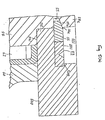
- Boss 54 of slant plate 50 includes smaller diameter portion 54a at an axially rearward end (to the right in Figure 1 and to the top in Figure 2) thereof, resulting in the formation of annular shoulder 541 forward of portion 54a.
- Annular balance weight ring 500 is mounted about smaller diameter portion 54a, in contact with shoulder 541.
- Balance weight ring 500 includes annular depression 501 formed at an inner periphery of the axially rearward surface, reducing the thickness of ring 500 at the inner periphery. Relatively thin plate portion 502 remains at the inner periphery of balance weight ring 500, forward of depression 501.
- annular groove 55 is formed in the radially outer peripheral surface of smaller diameter portion 54a, and annular snap ring 56 is disposed therein.
- Snap ring 56 includes annular tapered surface 56a formed at a radially inner portion of the axially rearward surface.
- Rearward annular wall 55a of annular groove 55 slants inwardly (to the left In Figure 2) at an angle generally corresponding to the angle of annular tapered surface 56a of snap ring 56 such that snap ring 56 may be slidably fitted and retained within groove 55.
- the radially outer portion of snap ring 56 extends exteriorly of groove 55 and contacts thin-plate portion 502 of balance weight ring 500. Thin plate portion 502 is retained between snap ring 56 and annular shoulder 541. Therefore, balance weight ring 500 is retained on boss 54.
- US-A-4073603 discloses a slant plate type refrigerant compressor comprising a compressor housing including a cylinder block, the cylinder block including a plurality of peripherally disposed cylinders, a crank chamber enclosed within the cylinder block at a location forward of the cylinders, the compressor housing including a suction chamber and a discharge chamber formed therein, a piston slidably fitted within each of the cylinders, a drive mechanism coupled to the piston to reciprocate the pistons within the cylinders, the drive mechanism including a drive shaft rotatably supported in the housing, the drive mechanism further including coupling means for coupling the drive shaft to the pistons such that rotary motion of the drive shaft is converted into reciprocating motion of the pistons in the cylinders, the coupling means including a slant plate disposed on the drive shaft and having a surface disposed at an inclined angle relative to the drive shaft, the slant plate having a boss, an annular balance weight disposed about the boss, the annular balance weight including a thin plate region
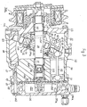
- Figure 1 shows a vertical longitudinal sectional view of a slant plate type refrigerant compressor in accordance with the prior art.
- Figure 2 shows an enlarged partial sectional view of the compressor shown in Figure 1 including the balance weight ring and retaining mechanism.
- Figure 3 shows a vertical longitudinal sectional view of a slant plate type refrigerant compressor in accordance with a first embodiment of the present invention.
- Figure 4 shows an enlarged partial sectional view of the compressor shown in Figure 3 including the balance weight ring and a retaining mechanism for preventing the ring from slipping off of the slant plate in accordance with a first embodiment of this invention.
- Figures 5(a) and 5(b), respectively, show an enlarged partial sectional view before and after formation of a retaining mechanism for a slant plate type refrigerant compressor in accordance with a third embodiment of the present invention.
- axial refers to a direction parallel to the longitudinal axis of the drive shaft
- radial refers to the perpendicular direction
- Compressor 10 includes cylindrical housing assembly 20 including cylinder block 21, front end plate 23 disposed at one end of cylinder block 21, crank chamber 22 formed between cylinder block 21 and front end plate 23, and rear end plate 24 disposed at the opposite end of cylinder block 21.
- Front end plate 23 is mounted on the open forward end of cylinder block 21 by a plurality of bolts 101 to enclose crank chamber 22 therein.
- Rear end plate 24 is mounted on cylinder block 21 at its opposite end by a plurality of bolts 102.
- Valve plate 25 is located between rear end plate 24 and cylinder block 21. Opening 231 is centrally formed in front end plate 23.
- Drive shaft 26 is supported by bearing 30 disposed in opening 231.
- Central bore 210 extends through cylinder block 21 to a rearward end surface.
- the inner (rear) end portion of drive shaft 26 is rotatably supported by bearing 31 disposed within central bore 210 of cylinder block 21.
- Valve control mechanism 19 is disposed in bore 210 to the rear of drive shaft 26.
- Cam rotor 40 is fixed on drive shaft 26 by pin member 261, and rotates with shaft 26.
- Thrust needle bearing 32 is disposed between the axial inner (rear) end surface of front end plate 23 and the adjacent forward axial end surface of cam rotor 40.
- Cam rotor 40 includes arm 41 having pin member 42 extending therefrom.
- Slant plate 50 is disposed about drive shaft 26 and includes opening 53 through which drive shaft 26 passes.
- Slant plate 50 is disposed adjacent cam rotor 40.
- Slant plate 50 includes arm 51 having slot 52, and boss 54.
- Cam rotor 40 and slant plate 50 are connected by pin member 42, which is inserted in slot 52 to create a hinged joint.
- Pin member 42 is slidable within a slot 52 to allow adjustment of the angular position of slant plate 50 with respect to the longitudinal axis of drive shaft 26.
- Wobble plate 60 is mounted about boss 54 of slant plate 50 through bearings 61 and 62 so that slant plate 50 is rotatable with respect thereto. Rotational motion of slant plate 50 causes nutational motion of wobble plate 60.
- Fork shaped slider 63 is attached to the outer peripheral end of wobble plate 60 and is slidably mounted on sliding rail 64 held between front end plate 23 and cylinder block 21. Fork shaped slider 63 prevents rotation of wobble plate 60 and wobble plate 60 reciprocates along rail 64 when cam rotor 40 and slant plate 50 rotate.
- Cylinder block 21 includes a plurality of peripherally located cylinder chambers 70 in which pistons 71 reciprocate. Each piston 71 is connected to wobble plate 60 at a peripheral location by a corresponding connecting rod 72. Nutational motion of wobble plate 60 causes pistons 71 to reciprocate in cylinders 70 to compress refrigerant therein.
- Rear end plate 24 includes peripherally located annular suction chamber 241 and centrally located discharge chamber 251.
- Valve plate 25 is located between cylinder block 21 and rear end plate 24 and includes a plurality of valved suction portions 242 linking suction chamber 241 with respective cylinders 70.
- Valve plate 25 also includes a plurality of valved discharge ports 252 linking discharge chamber 251 with respective cylinders 70.
- Suction ports 242 and discharge ports 252 are provided with suitable reed valves as described in U.S. Patent No. 4,011,029 to Shimizu.
- Suction chamber 241 includes inlet portion 241a which is connected to an evaporator of the external cooling circuit (not shown).
- Discharge chamber 251 is provided with outlet portion 251a connected to a condenser of the cooling circuit (not shown).
- Gaskets 27 and 28 are located between cylinder block 21 and the inner surface of valve plate 25, and the outer surface of valve plate 25 and rear end plate 24, respectively, to seal the mating surfaces of cylinder block 21, valve plate 25 and rear end plate 24.
- Communication path 600 links crank chamber 22 and suction chamber 241 and includes central bore 210 and passageway 150.
- Valve control mechanism 19 controls the opening and closing of communication path 600 in order to vary the capacity of the compressor, as disclosed in Japanese Patent Application Publication No. 01- 142,276.
- drive shaft 26 is rotated by the engine of the vehicle through electromagnetic clutch 300.
- Cam rotor 40 is rotated with drive shaft 26, rotating slant plate 50 as well, causing wobble plate 60 to nutate.
- Nutational motion of wobble plate 60 reciprocates pistons 71 in their respective cylinders 70.
- refrigerant gas which is introduced into suction chamber 241 through inlet portion 241a, flows into each cylinder 70 through suction ports 242 and is compressed therein.
- the compressed refrigerant gas is discharged into discharge chamber 251 from each cylinder 70 through discharge ports 252, and therefrom into the cooling circuit through outlet portion 251a.
- the capacity of compressor 10 may be adjusted to maintain a constant pressure in suction chamber 241 in response to a change in the heat load of the evaporator, or a change in the rotating speed of the compressor.
- the capacity of the compressor is adjusted by changing the angle of the slant plate with respect to a plane perpendicular to the axis of the drive shaft. This angle is dependent upon the crank chamber pressure. An increase in crank chamber pressure decreases the slant angle of the slant plate and the wobble plate, decreasing the capacity of the compressor.
- variable capacity mechanism 19 acts in response to the crank chamber pressure, such that the acting point is modified according to the discharge pressure, to control the link between the crank and suction chambers, to adjust the crank chamber pressure and thereby change the slant angle of slant plate 50 and vary the operating capacity of the compressor.
- variable displacement mechanisms or none at all may be used in compressors according to the present invention.
- compressor 10 further includes annular groove 55 formed in the radially outer surface of smaller diameter portion 54a of boss 54.
- Boss 54 includes annular shoulder 541 forward of smaller diameter portion 54a.
- Balance weight ring 500 includes annular depression 501 formed at a rearward, radially inner peripheral region, resulting in thin plate portion 502 formed axially forward of depression 501. Thin plate portion 502 fits on annular shoulder 541 of boss 54.
- Balance weight ring retaining mechanism 81 includes snap ring 56 disposed in groove 55 to the rear of portion 502. Ring 56 retains balance weight ring 500 on slant plate 50 by sandwiching portion 502 against shoulder 541.
- Mechanism 81 also includes annular member 811 disposed at an outer peripheral region of annular depression 501, surrounding snap ring 56.
- annular member 811 The width of annular member 811 is selected so as to limit the allowed radially outward expanding motion of snap ring 56, to ensure that snap ring 56 remains within groove 55 even when it is subjected to a radially expanding force which would tend to cause snap ring 56 to radially expand and slip out of groove 55.
- Annular groove 503 is formed in the radially outer surface of annular depression 501, axially rearward of thin plate portion 502.
- Snap ring 812 is disposed in groove 503, overlapping and in contact with ring member 811, and acts to retain ring member 811 in annular depression 501 of balance weight ring 500. Snap ring 56 is therefore retained in groove 55 by the provision of annular member 811 and snap ring 812, and prevents balance weight ring 500 from slipping off of slant plate 54.
- balance weight ring 500 is securely retained on smaller diameter portion 54a of boss 54 due to retaining mechanism 81. Even if snap ring 56 expands in response to the unusual operating conditions, since the extent of expansion of snap ring 56 is limited, balance weight ring 500 is maintained on boss 54.
- Retaining mechanism 83 includes snap ring 56 disposed in groove 55 of boss 54 to retain balance weight ring 500 on slant plate 50 as shown in Figure 4.
- Retaining mechanism 83 also includes annular member 831 made of soft metal, for example, untempered iron, and disposed around snap ring 56 on a radially outer portion of annular depression 501.
- Groove 504 is formed in the radially outer surface of annular depression 501 at the same axial location as annular member 831 and snap ring 56.
- Annular member 831 is caulked to the inner surface of groove 504 by application of annular caulking tool 200, which results in expansion of ring member 831 in both the radially inward and outward directions.
- Template 250 is disposed about caulking tool 200 to ensure that annular member 831 does not expand in the axial direction, As a result, the radially outer portion of annular member 831 is firmly secured within groove 504, and the radially inner surface of ring member 831 is adjacent the radially outer surface of snap ring 56, thereby limiting the allowed radially outward expansion of snap ring 56 when the compressor operates under unusual operating conditions. Therefore, snap ring 56 is securely retained in groove 55, and balance weight ring 500 is securely retained on boss 54 of slant plate 50.
- the caulking is performed completely around the inner periphery of the annular member or thin plate portion.
- the caulking may be performed only intermittently about the periphery, that is the caulking may be accomplished at three or more locations about the periphery at equal angular intervals.
Landscapes
- Engineering & Computer Science (AREA)
- Mechanical Engineering (AREA)
- General Engineering & Computer Science (AREA)
- Manufacturing & Machinery (AREA)
- Compressors, Vaccum Pumps And Other Relevant Systems (AREA)
- Compressor (AREA)
Claims (10)
- Compresseur de réfrigérant de type à plateau en biais (10) comprenant un carter de compresseur (20) muni d'un bloc de cylindres (21), ce bloc de cylindres comprenant un certain nombre de cylindres (70) disposés périphériquement, une chambre de vilebrequin (22) enfermée dans le bloc de cylindres (21) en un point situé en avant des cylindres, le carter de compresseur (20) comprenant une chambre d'aspiration (241) et une chambre de décharge (251) formées dans celui-ci, un piston (71) monté en glissement à l'intérieur de chacun des cylindres (70), un mécanisme d'entraînement couplé à chaque piston (71) pour faire aller et venir les pistons à l'intérieur des cylindres (70), le mécanisme d'entraînement comprenant un arbre d'entraînement (26) monté en rotation dans le carter (20), ce mécanisme d'entraînement comprenant en outre des moyens d'accouplement destinés à coupler l'arbre d'entraînement (26) aux pistons (71) de façon que le mouvement de rotation de l'arbre d'entraînement (26) soit transformé en un mouvement de va-et-vient des pistons (71) dans les cylindres (70), les moyens d'accouplement comprenant un plateau en biais (50) monté sur l'arbre d'entraînement (26) et présentant une surface disposée sous un certain angle d'inclinaison par rapport à l'arbre d'entraînement, le plateau en biais (50) comportant un bossage (54), un contrepoids annulaire (500) disposé autour du bossage, le contrepoids annulaire (500) comprenant une zone de plaque mince (502) délimitant une partie en creux (501), et des moyens de retenue comprenant une première rainure annulaire (55) formée sur le bossage (54) et un premier élément annulaire (56) disposé à la fois dans la rainure et dans la partie en creux (501), le premier élément annulaire (56) étant en contact avec la partie en creux (501) du contrepoids (500) pour retenir ce contrepoids sur le bossage (54) du plateau en biais (50), compresseur caractérisé en ce que les moyens de retenue comprennent en outre un second élément annulaire (811, 831) solidement placé dans la partie en creux (501) dans une disposition périphérique autour du premier élément annulaire (56), et le second élément annulaire (811, 831) servant à retenir solidement le premier élément annulaire (56) dans la rainure de manière à retenir solidement le contrepoids (500) sur le bossage (54).
- Compresseur selon la revendication 1, caractérisé en ce que le bossage (54) comprend une partie de diamètre resserré (54a) munie d'un épaulement annulaire (541), la première rainure annulaire (55) étant formée dans la partie de diamètre resserré (54a), et la zone de plaque mince (502) étant disposée sur l'épaulement annulaire (541) autour de la partie de diamètre resserré (54a).
- Compresseur selon l'une quelconque des revendications 1 et 2, caractérisé en ce qu'il comprend en outre une seconde rainure annulaire (503) disposée dans une surface radialement extérieure de la partie en creux (501), et un troisième élément annulaire (812) monté de façon fixe dans la seconde rainure annulaire (503) de manière à recouvrir et fixer le second élément annulaire (811) dans la partie en creux (501).
- Compresseur selon la revendication 3, caractérisé en ce que le premier élément annulaire (56) et le troisième élément annulaire (812) sont constitués par des bagues d'enclenchement, et en ce que le second élément annulaire (811) limite la dilatation radiale vers l'extérieur du premier élément annulaire (56).
- Compresseur selon l'une quelconque des revendications 1 et 2, caractérisé en ce qu'il comprend en outre une seconde rainure annulaire (504) formée dans une surface radialement extérieure de la partie en creux (501), et une partie radialement extérieure du second élément annulaire (831) solidement disposée dans la seconde rainure annulaire (504).
- Compresseur selon la revendication 5, caractérisé en ce que le second élément annulaire (831) est constitué par un métal mou et se trouve solidement fixé dans la seconde rainure annulaire (504) par matage.
- Compresseur selon la revendication 6, caractérisé en ce que le second élément annulaire (831) est complètement maté sur toute sa périphérie.
- Compresseur selon la revendication 6, caractérisé en ce que le second élément annulaire est maté en trois points ou plus répartis à des intervalles angulaires égaux sur sa périphérie.
- Compresseur selon l'une quelconque des revendications 6 à 8, caractérisé en ce que le premier élément annulaire (56) est constitué par une bague d'enclenchement et en ce que le métal mou est constitué par du fer doux.
- Compresseur selon l'une quelconque des revendications précédentes, caractérisé en ce que les moyens d'accouplement comprennent en outre un plateau oscillant (60) disposé autour du bossage (54), en ce que le plateau en biais (50) peut tourner solidairement de l'arbre d'entraînement (26), en ce que les pistons sont reliés au plateau oscillant (60) par des tiges de liaison (72), et en ce que le mouvement de rotation de l'arbre d'entraînement (26) et du plateau en biais (50) provoque un mouvement de nutation du plateau oscillant (60) et un mouvement de va-et-vient des pistons (71) dans les cylindres (70).
Priority Applications (3)
| Application Number | Priority Date | Filing Date | Title |
|---|---|---|---|
| EP92201235A EP0499341B1 (fr) | 1988-10-25 | 1989-10-18 | Compresseur à plateau oscillant |
| EP92201237A EP0499342B1 (fr) | 1988-10-25 | 1989-10-18 | Compresseur à plateau oscillant |
| EP92201238A EP0499343B1 (fr) | 1988-10-25 | 1989-10-18 | Compresseur à plateau oscillant |
Applications Claiming Priority (4)
| Application Number | Priority Date | Filing Date | Title |
|---|---|---|---|
| JP138136/88 | 1988-10-25 | ||
| JP1988138134U JPH082471Y2 (ja) | 1988-10-25 | 1988-10-25 | 容量可変圧縮機 |
| JP13813688U JPH0338458Y2 (fr) | 1988-10-25 | 1988-10-25 | |
| JP138134/88 | 1988-10-25 |
Related Child Applications (3)
| Application Number | Title | Priority Date | Filing Date |
|---|---|---|---|
| EP92201237.2 Division-Into | 1989-10-18 | ||
| EP92201235.6 Division-Into | 1989-10-18 | ||
| EP92201238.0 Division-Into | 1989-10-18 |
Publications (3)
| Publication Number | Publication Date |
|---|---|
| EP0366349A2 EP0366349A2 (fr) | 1990-05-02 |
| EP0366349A3 EP0366349A3 (en) | 1990-08-29 |
| EP0366349B1 true EP0366349B1 (fr) | 1993-03-31 |
Family
ID=26471255
Family Applications (4)
| Application Number | Title | Priority Date | Filing Date |
|---|---|---|---|
| EP92201235A Expired - Lifetime EP0499341B1 (fr) | 1988-10-25 | 1989-10-18 | Compresseur à plateau oscillant |
| EP92201237A Expired - Lifetime EP0499342B1 (fr) | 1988-10-25 | 1989-10-18 | Compresseur à plateau oscillant |
| EP89310709A Expired - Lifetime EP0366349B1 (fr) | 1988-10-25 | 1989-10-18 | Compresseur à plateau oscillant |
| EP92201238A Expired - Lifetime EP0499343B1 (fr) | 1988-10-25 | 1989-10-18 | Compresseur à plateau oscillant |
Family Applications Before (2)
| Application Number | Title | Priority Date | Filing Date |
|---|---|---|---|
| EP92201235A Expired - Lifetime EP0499341B1 (fr) | 1988-10-25 | 1989-10-18 | Compresseur à plateau oscillant |
| EP92201237A Expired - Lifetime EP0499342B1 (fr) | 1988-10-25 | 1989-10-18 | Compresseur à plateau oscillant |
Family Applications After (1)
| Application Number | Title | Priority Date | Filing Date |
|---|---|---|---|
| EP92201238A Expired - Lifetime EP0499343B1 (fr) | 1988-10-25 | 1989-10-18 | Compresseur à plateau oscillant |
Country Status (7)
| Country | Link |
|---|---|
| US (2) | US5062772A (fr) |
| EP (4) | EP0499341B1 (fr) |
| KR (1) | KR970003247B1 (fr) |
| CN (1) | CN1017272B (fr) |
| AU (5) | AU622494B2 (fr) |
| CA (1) | CA2001119C (fr) |
| DE (4) | DE68905750T2 (fr) |
Families Citing this family (10)
| Publication number | Priority date | Publication date | Assignee | Title |
|---|---|---|---|---|
| DE4211695C2 (de) * | 1991-04-08 | 1996-11-14 | Zexel Corp | Taumelscheibenverdichter |
| JP3026518B2 (ja) * | 1991-07-03 | 2000-03-27 | サンデン株式会社 | 容量可変型揺動板式圧縮機 |
| DE4405034A1 (de) * | 1994-02-17 | 1995-08-24 | Audi Ag | Axialkolben-Taumelscheiben-Kompressor |
| JPH09151846A (ja) * | 1995-11-30 | 1997-06-10 | Sanden Corp | 可変容量型斜板式圧縮機 |
| JPH11201033A (ja) | 1998-01-12 | 1999-07-27 | Sanden Corp | 斜板式圧縮機 |
| US6823768B2 (en) | 2001-11-22 | 2004-11-30 | Sanden Corporation | Nitrided surface layer on a swash plate boss |
| EP2746605B1 (fr) | 2007-07-04 | 2015-09-23 | NSK Ltd. | Procédé d'assemblage d'unité de roulement |
| JP5065158B2 (ja) * | 2008-06-02 | 2012-10-31 | サンデン株式会社 | 揺動板式可変容量圧縮機 |
| US9279325B2 (en) | 2012-11-08 | 2016-03-08 | General Electric Company | Turbomachine wheel assembly having slotted flanges |
| DE102015217443A1 (de) * | 2015-09-11 | 2017-03-30 | Bosch Mahle Turbo Systems Gmbh & Co. Kg | Lagergehäuse |
Family Cites Families (30)
| Publication number | Priority date | Publication date | Assignee | Title |
|---|---|---|---|---|
| US2182740A (en) * | 1937-12-18 | 1939-12-05 | Internat Supply Company | Counterbalance for crankshafts |
| US2776627A (en) * | 1952-07-10 | 1957-01-08 | Vickers Inc | Power transmission |
| DE1079577B (de) * | 1956-07-14 | 1960-04-14 | Friedrich Wilhelm Kiekert | Verfahren und Werkzeug zur Herstellung einer festen Verbindung zwischen einer Blechwand und einer mit Flansch versehenen Buchse |
| US3055100A (en) * | 1957-07-01 | 1962-09-25 | Zeller Corp | Method of forming interlocking joint between telescoped members |
| US3183848A (en) * | 1962-05-09 | 1965-05-18 | Hydro Kinetics Inc | Cartridge type pumping apparatus |
| US3246577A (en) * | 1963-12-23 | 1966-04-19 | Sundstrand Corp | Piston return mechanism |
| US3861829A (en) * | 1973-04-04 | 1975-01-21 | Borg Warner | Variable capacity wobble plate compressor |
| US4008005A (en) * | 1974-07-31 | 1977-02-15 | Sankyo Electric Company, Limited | Refrigerant compressor |
| DE2609970A1 (de) * | 1975-03-13 | 1976-09-30 | Central Automotive Ind | Kuehlgaskompressor |
| US4073603A (en) * | 1976-02-06 | 1978-02-14 | Borg-Warner Corporation | Variable displacement compressor |
| DE2611218A1 (de) * | 1976-03-17 | 1977-10-06 | Kugelfischer G Schaefer & Co | Form- und kraftschluessige verbindung von waelzlagerteilen mit umgebungsteilen |
| JPS53410A (en) * | 1976-06-23 | 1978-01-06 | Sanden Corp | Swinging type compressor |
| FR2371252A1 (fr) * | 1976-11-22 | 1978-06-16 | Letang & Remy Ets | Procede d'assemblage d'une piece sur une tole ou une plaque |
| US4145163A (en) * | 1977-09-12 | 1979-03-20 | Borg-Warner Corporation | Variable capacity wobble plate compressor |
| JPS54108009A (en) * | 1978-02-10 | 1979-08-24 | Sanden Corp | Oscillating compressor |
| JPS5823029Y2 (ja) * | 1978-07-01 | 1983-05-17 | サンデン株式会社 | 冷却用圧縮機 |
| NL7900076A (nl) * | 1979-01-05 | 1980-07-08 | Philips Nv | Drijfwerk voor een machine met heen- en weergaande zuigers met variabele slag. |
| US4475871A (en) * | 1982-08-02 | 1984-10-09 | Borg-Warner Corporation | Variable displacement compressor |
| DE8321186U1 (de) * | 1983-07-22 | 1987-04-23 | SKF GmbH, 8720 Schweinfurt | Vorrichtung zum Befestigen von Maschinenteilen |
| JPH0646018B2 (ja) * | 1985-01-23 | 1994-06-15 | 株式会社日立製作所 | 燃料微粒化装置 |
| US4771676A (en) * | 1986-05-19 | 1988-09-20 | Toshiba Kikai Kabushiki Kaisha | Hydraulic transmission device |
| JPS6316177A (ja) * | 1986-07-08 | 1988-01-23 | Sanden Corp | 容量可変型圧縮機 |
| JPS6351172U (fr) * | 1986-09-19 | 1988-04-06 | ||
| JPH0223829Y2 (fr) * | 1987-05-19 | 1990-06-28 | ||
| JPH0441262Y2 (fr) * | 1987-07-20 | 1992-09-28 | ||
| JP2511056B2 (ja) * | 1987-07-23 | 1996-06-26 | サンデン株式会社 | 容量可変型斜板式圧縮機 |
| JPS6429679A (en) * | 1987-07-24 | 1989-01-31 | Sanden Corp | Capacity variable swash plate type compressor |
| JPH01142276A (ja) * | 1987-11-27 | 1989-06-05 | Sanden Corp | 容量可変型斜板式圧縮機 |
| JP2503569B2 (ja) * | 1988-02-24 | 1996-06-05 | 株式会社豊田自動織機製作所 | ワブル型コンプレッサの駆動制御装置 |
| US4893994A (en) * | 1989-05-25 | 1990-01-16 | General Motors Corporation | Guide assembly and guide shoe for a variable angle wobble plate compressor |
-
1989
- 1989-10-18 DE DE8989310709T patent/DE68905750T2/de not_active Expired - Fee Related
- 1989-10-18 DE DE68920053T patent/DE68920053T2/de not_active Expired - Fee Related
- 1989-10-18 EP EP92201235A patent/EP0499341B1/fr not_active Expired - Lifetime
- 1989-10-18 DE DE68918954T patent/DE68918954T2/de not_active Expired - Fee Related
- 1989-10-18 EP EP92201237A patent/EP0499342B1/fr not_active Expired - Lifetime
- 1989-10-18 EP EP89310709A patent/EP0366349B1/fr not_active Expired - Lifetime
- 1989-10-18 EP EP92201238A patent/EP0499343B1/fr not_active Expired - Lifetime
- 1989-10-18 DE DE68918290T patent/DE68918290T2/de not_active Expired - Fee Related
- 1989-10-20 US US07/424,691 patent/US5062772A/en not_active Expired - Lifetime
- 1989-10-20 CA CA002001119A patent/CA2001119C/fr not_active Expired - Fee Related
- 1989-10-20 AU AU43608/89A patent/AU622494B2/en not_active Ceased
- 1989-10-24 KR KR1019890015253A patent/KR970003247B1/ko not_active Expired - Fee Related
- 1989-10-25 CN CN89108230A patent/CN1017272B/zh not_active Expired
-
1991
- 1991-05-23 US US07/705,056 patent/US5106271A/en not_active Expired - Lifetime
-
1992
- 1992-01-22 AU AU10388/92A patent/AU1038892A/en not_active Abandoned
- 1992-01-22 AU AU10389/92A patent/AU631756B2/en not_active Ceased
- 1992-01-22 AU AU10391/92A patent/AU631758B2/en not_active Ceased
- 1992-01-22 AU AU10390/92A patent/AU631757B2/en not_active Ceased
Also Published As
Similar Documents
| Publication | Publication Date | Title |
|---|---|---|
| EP0410453B1 (fr) | Mécanisme de lubrification d'un montage de piston pour un compresseur à plateau en biais | |
| EP0372913B1 (fr) | Compresseur à plateau en biais | |
| EP0486257B1 (fr) | Compresseur à plateau en biais avec mécanisme de contrôle de capacité | |
| AU616512B2 (en) | Slant plate type compressor with variable displacement mechanism | |
| EP0318316B1 (fr) | Compresseur à plateau en biais avec mécanisme à déplacement variable | |
| EP0405878B1 (fr) | Compresseur à plateau en biais avec mécanisme à déplacement variable | |
| US5425303A (en) | Slant plate-type compressor with variable displacement mechanism | |
| EP0845593B1 (fr) | Appareil de commande pour compresseur à plateau en biais à déplacement variable | |
| EP0653563B1 (fr) | Compresseur à plateau en biais avec mécanisme à déplacement variable | |
| US4913627A (en) | Wobble plate type compressor with variable displacement mechanism | |
| EP0366349B1 (fr) | Compresseur à plateau oscillant | |
| US5255569A (en) | Slant plate type compressor with variable displacement mechanism | |
| EP0318976B1 (fr) | Compresseur à plateau en biais avec mécanisme à déplacement variable | |
| US5039282A (en) | Slant plate type compressor with variable displacement mechanism | |
| US5873706A (en) | Valved suction mechanism for refrigerant compressor | |
| US5299918A (en) | Bearing for compressor drive shaft |
Legal Events
| Date | Code | Title | Description |
|---|---|---|---|
| PUAI | Public reference made under article 153(3) epc to a published international application that has entered the european phase |
Free format text: ORIGINAL CODE: 0009012 |
|
| AK | Designated contracting states |
Kind code of ref document: A2 Designated state(s): DE FR GB IT SE |
|
| PUAL | Search report despatched |
Free format text: ORIGINAL CODE: 0009013 |
|
| AK | Designated contracting states |
Kind code of ref document: A3 Designated state(s): DE FR GB IT SE |
|
| 17P | Request for examination filed |
Effective date: 19901207 |
|
| 17Q | First examination report despatched |
Effective date: 19920218 |
|
| GRAA | (expected) grant |
Free format text: ORIGINAL CODE: 0009210 |
|
| AK | Designated contracting states |
Kind code of ref document: B1 Designated state(s): DE FR GB IT SE |
|
| ET | Fr: translation filed | ||
| REF | Corresponds to: |
Ref document number: 68905750 Country of ref document: DE Date of ref document: 19930506 |
|
| ITF | It: translation for a ep patent filed | ||
| PLBE | No opposition filed within time limit |
Free format text: ORIGINAL CODE: 0009261 |
|
| STAA | Information on the status of an ep patent application or granted ep patent |
Free format text: STATUS: NO OPPOSITION FILED WITHIN TIME LIMIT |
|
| 26N | No opposition filed | ||
| EAL | Se: european patent in force in sweden |
Ref document number: 89310709.4 |
|
| PGFP | Annual fee paid to national office [announced via postgrant information from national office to epo] |
Ref country code: SE Payment date: 20011005 Year of fee payment: 13 |
|
| PGFP | Annual fee paid to national office [announced via postgrant information from national office to epo] |
Ref country code: FR Payment date: 20011010 Year of fee payment: 13 |
|
| PGFP | Annual fee paid to national office [announced via postgrant information from national office to epo] |
Ref country code: GB Payment date: 20011017 Year of fee payment: 13 |
|
| PGFP | Annual fee paid to national office [announced via postgrant information from national office to epo] |
Ref country code: DE Payment date: 20011105 Year of fee payment: 13 |
|
| REG | Reference to a national code |
Ref country code: GB Ref legal event code: IF02 |
|
| PG25 | Lapsed in a contracting state [announced via postgrant information from national office to epo] |
Ref country code: GB Free format text: LAPSE BECAUSE OF NON-PAYMENT OF DUE FEES Effective date: 20021018 |
|
| PG25 | Lapsed in a contracting state [announced via postgrant information from national office to epo] |
Ref country code: SE Free format text: LAPSE BECAUSE OF NON-PAYMENT OF DUE FEES Effective date: 20021019 |
|
| PG25 | Lapsed in a contracting state [announced via postgrant information from national office to epo] |
Ref country code: DE Free format text: LAPSE BECAUSE OF NON-PAYMENT OF DUE FEES Effective date: 20030501 |
|
| EUG | Se: european patent has lapsed | ||
| GBPC | Gb: european patent ceased through non-payment of renewal fee |
Effective date: 20021018 |
|
| PG25 | Lapsed in a contracting state [announced via postgrant information from national office to epo] |
Ref country code: FR Free format text: LAPSE BECAUSE OF NON-PAYMENT OF DUE FEES Effective date: 20030630 |
|
| REG | Reference to a national code |
Ref country code: FR Ref legal event code: ST |
|
| PG25 | Lapsed in a contracting state [announced via postgrant information from national office to epo] |
Ref country code: IT Free format text: LAPSE BECAUSE OF NON-PAYMENT OF DUE FEES;WARNING: LAPSES OF ITALIAN PATENTS WITH EFFECTIVE DATE BEFORE 2007 MAY HAVE OCCURRED AT ANY TIME BEFORE 2007. THE CORRECT EFFECTIVE DATE MAY BE DIFFERENT FROM THE ONE RECORDED. Effective date: 20051018 |