EP0366380A2 - Image scanning and printing apparatus - Google Patents
Image scanning and printing apparatus Download PDFInfo
- Publication number
- EP0366380A2 EP0366380A2 EP89310872A EP89310872A EP0366380A2 EP 0366380 A2 EP0366380 A2 EP 0366380A2 EP 89310872 A EP89310872 A EP 89310872A EP 89310872 A EP89310872 A EP 89310872A EP 0366380 A2 EP0366380 A2 EP 0366380A2
- Authority
- EP
- European Patent Office
- Prior art keywords
- scanning
- printing
- printing apparatus
- recording medium
- document
- Prior art date
- Legal status (The legal status is an assumption and is not a legal conclusion. Google has not performed a legal analysis and makes no representation as to the accuracy of the status listed.)
- Granted
Links
Images



Classifications
-
- H—ELECTRICITY
- H04—ELECTRIC COMMUNICATION TECHNIQUE
- H04N—PICTORIAL COMMUNICATION, e.g. TELEVISION
- H04N1/00—Scanning, transmission or reproduction of documents or the like, e.g. facsimile transmission; Details thereof
- H04N1/04—Scanning arrangements, i.e. arrangements for the displacement of active reading or reproducing elements relative to the original or reproducing medium, or vice versa
- H04N1/207—Simultaneous scanning of the original picture and the reproduced picture with a common scanning device
-
- H—ELECTRICITY
- H04—ELECTRIC COMMUNICATION TECHNIQUE
- H04N—PICTORIAL COMMUNICATION, e.g. TELEVISION
- H04N1/00—Scanning, transmission or reproduction of documents or the like, e.g. facsimile transmission; Details thereof
- H04N1/46—Colour picture communication systems
- H04N1/48—Picture signal generators
- H04N1/482—Picture signal generators using the same detector device sequentially for different colour components
-
- H—ELECTRICITY
- H04—ELECTRIC COMMUNICATION TECHNIQUE
- H04N—PICTORIAL COMMUNICATION, e.g. TELEVISION
- H04N1/00—Scanning, transmission or reproduction of documents or the like, e.g. facsimile transmission; Details thereof
- H04N1/46—Colour picture communication systems
- H04N1/50—Picture reproducers
- H04N1/506—Reproducing the colour component signals picture-sequentially, e.g. with reproducing heads spaced apart from one another in the subscanning direction
- H04N1/508—Reproducing the colour component signals picture-sequentially, e.g. with reproducing heads spaced apart from one another in the subscanning direction using the same reproducing head for two or more colour components
Definitions
- a scanning and printing apparatus is the electrophotographic copier in, which a document is placed face-down on a glass window called a copyboard, a cover is closed over the document, and the document is scanned by a movable scanning unit disposed below the copyboard.
- the scanning unit converts the image on the document to electrical signals which are sent to a printing unit comprising, for example, a rotating drum, a toner developing system, and a paper cassette.
- a printing unit comprising, for example, a rotating drum, a toner developing system, and a paper cassette.
- Color copiers comprising a thermal or ink-jet printing unit have also been developed.
- a typical color copier of this type scans a document three times, once for each of three primary colors, and transports the paper through the printing unit three times to have each color printed separately. Since the scanning speed is not in general equal to the printing speed, a buffer memory is needed to store the signals from the scanning unit before they are printed by the printing unit. It may further be necessary to process the signals sent from the scanning unit to the printing unit to compensate for differences between the spectral characteristics of the filters in the scanning unit and the inks in the printing unit.
- a facsimile machine is similar in function, except that instead of sending electrical signals from its scanning unit to its printing unit, a facsimile machine sends signals from its scanning unit to a distant facsimile machine, and prints images received from a distant facsimile machine.
- a problem of all these devices is their large size and high cost, which result from their complex internal structure.
- One cause of this problem is that the scanning unit and printing unit are independent, each having its own driving system.
- Many prior-art color copiers for example, simply comprise a color scanner mounted atop a color thermal printer, the two units being completely separate except for the electrical interface between them.
- an associated problem is that to prevent distortion of the copied image, the speed of the driving system for the scanning unit must be accurately related to the speed of the driving system for paper transport in the printing unit. Expensive, high-precision stepping motors must therefore be used in these driving systems, and even so, distortion may occur due to vibration of the apparatus, or to motor irregularities.
- An object of this invention is accordingly to simplify the structure of a scanning and printing apparatus.
- Another object is to solve problems of synchronization of scanning and printing speeds.
- a scanning and printing apparatus for flatbed scanning of documents and printing of document images comprises driving means for generating a linear, reciprocal motion, scanning means coupled to and reciprocally moved by the driving means for scanning a document and converting an image thereof to electrical signals, clamping means coupled to and reciprocally moved by the driving means for holding one edge of a recording medium, thereby moving the recording medium in a reciprocal manner, and printing means for printing an image on the recording medium as the recording medium is moved by the clamping means.
- the clamping means is also coupled to and reciprocally moved by the driving means.
- the clamping means comprises a lever 31 attached to the carriage 22 and actuated by a well-known mechanism such as a spring and electromagnet, which are not shown in the drawing.
- the function of the lever 31 is to hold one edge of a recording medium 35 such as a sheet of paper, thereby moving the recording medium 35 in a reciprocal manner.
- the ink sheet 46 is also fed into the space between the platen roller 44 and the thermal print head 45, the ink sheet 46 being disposed between the thermal print head 45 and the recording medium 35.
- the ink sheet 46 is wound on the reels 47, which turn so that the ink sheet 46 can move in contact with the recording medium 35.
- the ink sheet 46 is coated with ink that melts or sublimes when heated, thus being transferred to the recording medium 35.
- the lever 31 releases the recording medium 35.
- the platen roller 44 and other rollers continue turning to deliver the recording medium 35 into a tray, for example, disposed to the right of the arrow "c," not shown in the drawing.
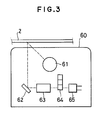
- the structure of the image sensor 60 in Fig. 2 is shown in greater detail in Fig. 3.
- the image sensor 60 comprises illumination means such as a fluorescent lamp 61, a mirror 62, reducing optical means such as a lens 63, color filters 64, and photodetector means such as an array of photodetector elements 65.
- illumination means such as a fluorescent lamp 61
- a mirror 62 reducing optical means such as a lens 63
- color filters 64 such as an array of photodetector elements 65.
- the color filters 64 transmit three different primary colors, such as yellow, magenta, and cyan, enabling these colors to be scanned separately.
- the operation of the scanning and printing apparatus in Fig. 2 is similar to the operation of the scanning and printing apparatus in Fig. 1 except that the document 2 is scanned three times, once per color.
- the signal processing circuit 52 may comprise further circuits for processing the electrical signals transmitted from the scanning means to the printing means. Processes such as edge enhancement and intensity-scale adjustment can be performed, for example, or the image can be enlarged or reduced. Reduction and enlargement processes can be carried out entirely in the signal processing circuit 52 by combining or interpolating dots. Alternatively, the signal processing circuit 52 can perform enlargement and reduction in the lateral direction, leaving enlargement and reduction in the lengthwise direction to be performed by running the motor 11 and the platen roller 44 at a faster or slower speed in the reverse direction during printing than in the forward direction during scanning.
- This scanning and printing apparatus is similar to the one in Fig. 1 except for the structure of its driving and scanning means.
- the second part comprises a second mirror 73 and a third mirror 74. These are coupled to the second wire 18 and driven in the same direction as the clamping lever 31 but at half the speed.
- Printing and scanning sequences other than the ones described can be employed.
- the first color can be simultaneously scanned and printed as the scanning means moves in one direction; then the second color can be simultaneously scanned and printed as the scanning means returns in the opposite direction.
- all scanning and printing operations can be performed separately and in the same direction, using two full reciprocating cycles for each color.
Landscapes
- Engineering & Computer Science (AREA)
- Multimedia (AREA)
- Signal Processing (AREA)
- Facsimile Scanning Arrangements (AREA)
- Electronic Switches (AREA)
- Fax Reproducing Arrangements (AREA)
Abstract
Description
- This invention relates to a scanning and printing apparatus, such as a copier or facsimile machine, for flatbed scanning of documents and printing of document images.
- A familiar example of such, a scanning and printing apparatus is the electrophotographic copier in, which a document is placed face-down on a glass window called a copyboard, a cover is closed over the document, and the document is scanned by a movable scanning unit disposed below the copyboard. Traversing the document lengthwise, the scanning unit converts the image on the document to electrical signals which are sent to a printing unit comprising, for example, a rotating drum, a toner developing system, and a paper cassette. By extracting a sheet of paper from the cassette, transporting it under the drum, and transferring toner from the drum to the paper, the printing unit prints a black-and-white copy of the scanned image.
- Color copiers comprising a thermal or ink-jet printing unit have also been developed. A typical color copier of this type scans a document three times, once for each of three primary colors, and transports the paper through the printing unit three times to have each color printed separately. Since the scanning speed is not in general equal to the printing speed, a buffer memory is needed to store the signals from the scanning unit before they are printed by the printing unit. It may further be necessary to process the signals sent from the scanning unit to the printing unit to compensate for differences between the spectral characteristics of the filters in the scanning unit and the inks in the printing unit.
- A facsimile machine is similar in function, except that instead of sending electrical signals from its scanning unit to its printing unit, a facsimile machine sends signals from its scanning unit to a distant facsimile machine, and prints images received from a distant facsimile machine.
- A problem of all these devices is their large size and high cost, which result from their complex internal structure. One cause of this problem is that the scanning unit and printing unit are independent, each having its own driving system. Many prior-art color copiers, for example, simply comprise a color scanner mounted atop a color thermal printer, the two units being completely separate except for the electrical interface between them.
- In a copier, an associated problem is that to prevent distortion of the copied image, the speed of the driving system for the scanning unit must be accurately related to the speed of the driving system for paper transport in the printing unit. Expensive, high-precision stepping motors must therefore be used in these driving systems, and even so, distortion may occur due to vibration of the apparatus, or to motor irregularities.
- An object of this invention is accordingly to simplify the structure of a scanning and printing apparatus.
- Another object is to solve problems of synchronization of scanning and printing speeds.
- A scanning and printing apparatus for flatbed scanning of documents and printing of document images comprises driving means for generating a linear, reciprocal motion, scanning means coupled to and reciprocally moved by the driving means for scanning a document and converting an image thereof to electrical signals, clamping means coupled to and reciprocally moved by the driving means for holding one edge of a recording medium, thereby moving the recording medium in a reciprocal manner, and printing means for printing an image on the recording medium as the recording medium is moved by the clamping means.
-
- Fig. 1 is a sectional view of a monochrome scanning and printing apparatus.
- Fig. 2 is a sectional view of a color scanning and printing apparatus.
- Fig. 3 is a more detailed, schematic view of the image sensor in Fig. 2.
- Fig. 4 is a sectional view of another color scanning and printing apparatus.
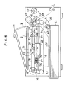
- Fig. 5 is a sectional view of yet another color scanning and printing apparatus.
- A novel scanning and printing apparatus for flatbed scanning of documents and printing of document images will be described with reference to Figs. 1 to 5. The description will deal mainly with applications to copiers, but facsimile applications will also be briefly discussed.
- The novel scanning and printing apparatus illustrated in Fig. 1 is a monochrome copier for making a black-and-white copy of a document. The apparatus has a
cover 1 which can be opened to permit adocument 2 to be placed face-down on acopyboard 3. Thecopyboard 3 is a sheet of transparent material such as glass. - Internally, the scanning and printing apparatus comprises a driving means, a scanning means, a clamping means, and a printing means.
- The driving means in Fig. 1 comprises a
motor 11, abelt 12, afirst pulley 13, asecond pulley 14, and awire 15. Themotor 11, which may be a stepping motor for example, is controlled so as to turn in first one direction, then the opposite direction. Themotor 11 drives thebelt 12 which turns thefirst pulley 13, thus generating a linear, reciprocating motion of thewire 15 which is strung on the first andsecond pulleys - The scanning means is coupled to and reciprocally moved by the driving means so as to scan the
document 2. In Fig. 1 the scanning means comprises aguide rail 21, acarriage 22, and a contact-type line sensor 23. Thecarriage 22 is movably mounted on theguide rail 21 and attached to the two ends of thewire 15. The contact-type line sensor 23 is rigidly mounted on thecarriage 22. Thus as themotor 11 turns in first one direction then the other, thewire 15 pulls thecarriage 22 back and forth along theguide rail 21, causing the contact-type line sensor 23 to scan thedocument 2 from beneath. - The contact-
type line sensor 23 comprises, for example, a linear array ofrod lenses 24 and photodetector elements 25. Light generated bylight sources 26 is reflected from thedocument 2 and channeled by therod lenses 24 to the photodetector elements 25, which generate electrical signals representative of the intensity of the received light. At a given position of thecarriage 22, the photodetector elements 25 thus generate signals representing the intensity of a line of adjacent dot-shaped areas extending laterally across thedocument 2. By moving lengthwise along thedocument 2, the contact-type line sensor 23 converts an image of theentire document 2 to electrical signals. - The clamping means is also coupled to and reciprocally moved by the driving means. In Fig. 1 the clamping means comprises a
lever 31 attached to thecarriage 22 and actuated by a well-known mechanism such as a spring and electromagnet, which are not shown in the drawing. The function of thelever 31 is to hold one edge of arecording medium 35 such as a sheet of paper, thereby moving therecording medium 35 in a reciprocal manner. - As the
recording medium 35 is moved by the clamping means, the printing means prints an image on therecording medium 35. In Fig. 1 the printing means is a thermal printer comprising acassette 41, a pick-up roller 42, one ormore guide rollers 43, aplaten roller 44, athermal print head 45, anink sheet 46, and a pair ofreels 47. Thecassette 41 accommodates one or more sheets of therecording medium 35. The pick-up roller 42 is disposed in contact with the top sheet of therecording medium 35, its function being to feed therecording medium 35 past theguide rollers 43 into the space betweenplaten roller 44 and thethermal print head 45. Thethermal print head 45 comprises a linear array of resistive heating elements. Theink sheet 46 is also fed into the space between theplaten roller 44 and thethermal print head 45, theink sheet 46 being disposed between thethermal print head 45 and therecording medium 35. Theink sheet 46 is wound on thereels 47, which turn so that theink sheet 46 can move in contact with therecording medium 35. Theink sheet 46 is coated with ink that melts or sublimes when heated, thus being transferred to therecording medium 35. - Since the scanning and printing apparatus in Fig. 1 is a copier, it also comprises
signal lines 51 for transmitting electrical signals from the scanning means to the printing means. More specifically, thesignal lines 51 comprise lines coupling the photodetector elements 25 to circuits such as transistor circuits driving respective heating elements in thethermal print head 45. - Next the operation of the scanning and printing apparatus in Fig. 1 will be described.
- Operation begins with the
carriage 22 at the right-most position in the drawing, even with the line marked A-A, and thelever 31 in a raised position. Adocument 2 is placed on thecopyboard 3, thecover 1 is closed to shut out ambient light, and a control button not shown in the drawing is pressed. The pick-up roller 42 then begins turning in the direction of the arrow "a," feeding a sheet ofrecording medium 35 past theguide rollers 43 and between theplaten roller 44 and thethermal print head 45. Feeding continues until the front edge of therecording medium 35 is under thelever 31. Then the pick-up roller 42 releases therecording medium 35 and thelever 31 is actuated to clamp the front edge of therecording medium 35 as shown in the drawing. - The
motor 11 now begins to turn counterclockwise, moving thecarriage 22 in the direction of the arrow "b" in the drawing, simultaneously moving the contact-type line sensor 23 beneath thedocument 2 and pulling therecording medium 35 past thethermal print head 45. At the same time thethermal print head 45 moves down to press theink sheet 46 and therecording medium 35 against theplaten roller 44, and thereels 47 turn to allow theink sheet 46 to move together with therecording medium 35. - As the contact-
type line sensor 23 moves beneath thedocument 2 it scans successive lines of dots, converting their intensity values to electrical signals as already explained. These electrical signals are transmitted via thesignal lines 51 to thethermal print head 45, where they drive the transistor circuits for turning on and off the currents to the respective heating elements in thethermal print head 45. - Specifically, current is provided to the heating elements that correspond to dark dots in the line currently viewed by the contact-
type line sensor 23, generating heat that transfers ink from theink sheet 46 to therecording medium 35. Thus a pattern of dots is printed on therecording medium 35 matching the pattern viewed by the contact-type line sensor 23. As thecarriage 22 moves in the direction of the arrow "b" successive lines are scanned and printed in this way until an image of theentire document 2 has been printed on therecording medium 35. - The
motor 11 now reverses direction and drives thecarriage 22 in the opposite direction back toward its starting position at A-A. Theplaten roller 44 also reverses direction, so that therecording medium 35 moves to the right in the drawing without buckling. The natural stiffness of therecording medium 35 causes it to feed out in the direction of the arrow "c" in the drawing. During this reverse motion thethermal print head 45 and theink sheet 46 are raised so that they do not press against therecording medium 35. - When the
carriage 22 has returned to the position A-A, thelever 31 releases therecording medium 35. Theplaten roller 44 and other rollers continue turning to deliver therecording medium 35 into a tray, for example, disposed to the right of the arrow "c," not shown in the drawing. - An advantage of the scanning arid printing apparatus in Fig. 1 is that the same driving means moves both the contact-
type line sensor 23 and therecording medium 35. The apparatus is thus more compact and economical than prior-art apparatus, requiring fewer motors, belts, pulleys, and wires. - An associated advantage is that the motion of the
recording medium 35 during printing is automatically synchronized with the motion of the contact-type line sensor 23 during scanning, so image distortion does not occur even in the presence of vibration, or if themotor 11 does not operate with perfect regularity. It is accordingly not necessary for themotor 11 to be a stepping motor; a less expensive direct-current or alternating-current induction motor can be used. - Another advantage is that, since the electrical signals from the contact-
type line sensor 23 drive thethermal print head 45 directly, no buffer memory or other interface circuitry is needed. - Next a scanning and printing apparatus for scanning and printing color images will be described with reference to Figs. 2 and 3. Structurally, this scanning and printing apparatus is identical to the apparatus in Fig. 1 except that it employs an
image sensor 60 instead of a contact-type line sensor, and has amulticolor ink sheet 48. - The structure of the
image sensor 60 in Fig. 2 is shown in greater detail in Fig. 3. Theimage sensor 60 comprises illumination means such as afluorescent lamp 61, amirror 62, reducing optical means such as alens 63,color filters 64, and photodetector means such as an array ofphotodetector elements 65. Light emitted by thefluorescent lamp 61 is reflected from the underside of thedocument 2, reflected by themirror 62, and focused by thelens 63 through thecolor filters 64 onto thephotodetector elements 65. The color filters 64 transmit three different primary colors, such as yellow, magenta, and cyan, enabling these colors to be scanned separately. - The
multicolor ink sheet 48 in Fig. 2 has inks of the same three primary colors disposed in separate areas sequentially arranged along the length of the ink sheet, the spectral reflectance characteristics of respective inks being substantially identical to the spectral transmittance characteristics of the color filters 64. - The operation of the scanning and printing apparatus in Fig. 2 is similar to the operation of the scanning and printing apparatus in Fig. 1 except that the
document 2 is scanned three times, once per color. - In the first scan, the
color filters 64 are positioned so that the light from thelens 63 passes through the yellow filter, and themulticolor ink sheet 48 is positioned so that a yellow area faces therecording medium 35. Thus as thecarriage 22 moves in the direction of the arrow "b," an image of the yellow component of thedocument 2 is printed on therecording medium 35. When yellow scanning is complete, themotor 11 andplaten roller 44 reverse and thereels 47 andmulticolor ink sheet 48 move away from theplaten roller 44 as before, but when thecarriage 22 returns to the position A-A, thelever 31 does not release therecording medium 35. - Next the
color filters 64 are repositioned so that the light from thelens 63 passes through the magenta filter, and themulticolor ink sheet 48 is repositioned (if necessary) so that a magenta area faces therecording medium 35. Themotor 11 andplaten roller 44 now reverse again to start the second scan. This scan is performed in exactly the same way as the first, printing an image of the magenta component of thedocument 2 on therecording medium 35, superimposed on the yellow image. - Finally, the
color filters 64 are repositioned so that the light from thelens 63 passes through the cyan filter, themulticolor ink sheet 48 is repositioned (if necessary) so that a cyan area faces therecording medium 35, and a third scan is performed to print an image of the cyan component of thedocument 2 on therecording medium 35, superimposed on the yellow and magenta images. At the end of this scan, when thecarriage 22 returns to the position A-A thelever 31 releases therecording medium 35 so that it can be fed out in the direction of the arrow "c." The superimposed images in the three primary colors combine to produce a full-color copy of thedocument 2 on therecording medium 35. - Matching of the spectral characteristics of the
color filters 64 and the inks on themulticolor ink sheet 48 enables the signals from theimage sensor 60 to drive thethermal print head 45 directly, without the need for compensating circuits as in the prior art. - A variation of the scanning and printing apparatus in Fig. 2 will next be described with reference to Fig. 4. The scanning and printing apparatus in Fig. 4 is similar to the scanning and printing apparatus in Fig. 2, but also has a
signal processing circuit 52 disposed on thesignal lines 51 between theimage sensor 60 and thethermal print head 45. Thesignal processing circuit 52 comprises a memory circuit for temporary storage of the electrical signals produced by theimage sensor 60 before they are transmitted to thethermal print head 45. The operation of the scanning and printing apparatus in Fig. 4 is similar to the operation of the scanning and printing apparatus in Fig. 2 except that the document is scanned while the driving means drives the scanning and clamping means in one direction, and the corresponding color image is printed while the driving means drives the scanning and clamping means in the reverse direction. - In the yellow scan, for example, as the
motor 11 drives thecarriage 22 in the direction of the arrow "b," thethermal print head 45 and themulticolor ink sheet 48 are raised so that they do not contact therecording medium 35, and the signals representing the yellow component of the image are stored as data in thesignal processing circuit 52. Then whenmotor 11 and theplaten roller 44 reverse to move therecording medium 35 back to the right in the drawing, thethermal print head 45 and themulticolor ink sheet 48 are lowered and the signal data stored in thesignal processing circuit 52 are read out in reverse order and sent to thethermal print head 45, causing it to print the yellow component of the image on therecording medium 35. - The magenta and cyan components are scanned and printed in the same way, producing a full-color copy of the
document 2. - In addition to a memory circuit, the
signal processing circuit 52 may comprise further circuits for processing the electrical signals transmitted from the scanning means to the printing means. Processes such as edge enhancement and intensity-scale adjustment can be performed, for example, or the image can be enlarged or reduced. Reduction and enlargement processes can be carried out entirely in thesignal processing circuit 52 by combining or interpolating dots. Alternatively, thesignal processing circuit 52 can perform enlargement and reduction in the lateral direction, leaving enlargement and reduction in the lengthwise direction to be performed by running themotor 11 and theplaten roller 44 at a faster or slower speed in the reverse direction during printing than in the forward direction during scanning. - Next another scanning and printing apparatus will be described with reference to Fig. 5. This scanning and printing apparatus is similar to the one in Fig. 1 except for the structure of its driving and scanning means.
- The driving means in Fig. 5 comprises a
motor 11, abelt 12, afirst pulley 13, asecond pulley 14, and awire 15 which are identical or equivalent to the elements with the same numbers in Fig. 1, and athird pulley 16, a fourth pulley 17, and a second wire 18. The relative sizes of the first andsecond pulleys fourth pulleys 16 and 17 are such that the second wire 18 is driven at half the speed of thewire 15. - The optical system of the scanning means in Fig. 5 has three separate parts.
- The first part comprises illumination means such as a
fluorescent lamp 71 and afirst mirror 72. These are mounted on thecarriage 22 and driven by thewire 15 at the same speed as the clampinglever 31. - The second part comprises a
second mirror 73 and athird mirror 74. These are coupled to the second wire 18 and driven in the same direction as the clampinglever 31 but at half the speed. - The third part is stationary and comprises reducing optical means such as a
lens 75, and photodetector means such as an array ofphotodetector elements 76. It is this stationary part of the scanning means that is connected by thesignal lines 51 to thethermal print head 45. Accordingly, it is not necessary for one end of thesignal lines 51 to move together with the scanning motion of thecarriage 22, as in Figs. 1, 2, and 4. - Aside from the structural difference in the driving and scanning means, the scanning and printing apparatus in Fig. 5 operates like that in Fig. 1. Due to the relative speeds of the first and second parts of the scanning means, the length of the optical path from the
document 2 to the array ofphotodetector elements 76 remains constant throughout the scan. - For scanning and printing of color images,
color filters 77 may be inserted between thelens 75 and thephotodetector elements 76. - Although the scanning and printing apparatus in Figs. 1 to 5 have all been described as copiers, with a single modification the same structures can be used in facsimile apparatus. The modification is that instead of being connected to each other by
signal lines 51, the scanning means and printing means are both connected through an interface unit to a communication line such as a telephone line. The interface unit comprises well-known circuits such as modulator and demodulator circuits and control circuits, enabling the scanning and printing apparatus to transmit images to and receive images from a distant facsimile machine. - In the transmit mode of operation, the
carriage 22 moves to scan thedocument 2 and the electrical signals generated are sent over the communication line to the distant facsimile machine, while the entire printing means remains idle. The pick-uproller 42 does not feed therecording medium 35, theguide rollers 43, theplaten roller 44, and thereels 47 do not turn, and power is not supplied to thethermal print head 45. - In the receive mode, the printing means is active. The
cassette 41feeds recording medium 35 to thelever 31, which clamps it and moves together with thecarriage 22, transporting therecording medium 35 while thethermal print head 45 prints an image according to electrical signals received from the distant facsimile machine. The scanning means also moves, but the illumination means are not switched on and no electrical signals are generated. - The scope of this invention is not limited to the structures described in the drawings, but includes many modifications that will be apparent to one skilled in the art. For example, use of a contact-type line sensor for monochrome scanning and an image sensor for color scanning was described, but it is also possible to use an image sensor for monochrome scanning or, with a suitable arrangement of color filters and photodetector elements, to use a contact-type line scanner for color scanning. An example of the image sensor for use with the reducing optical system is a CCD image sensor.
- In place of the combination of the color filters and the monochrome image sensor, a color line sensor having groups of photo-detector elements, each group of the sensors being sensitive to a particular color, e.g., one of the three primary colors may be used.
- In color scanning and printing, the primary colors need not be yellow, magenta, and cyan, and the number of colors need not be three. For example, it is possible to use four colors such as yellow, magenta, cyan, and black, or two colors such as black and red.
- The printing means may comprise an ink-jet or dot matrix print head instead of a thermal print head.
- The clamping means need not be attached to the scanning means as shown in Figs. 1, 2, 4, and 5. It can be attached to the
wire 15 at a separate location. - Although only a
single guide rail 21 was shown in Figs. 1, 2, 4, and 5, thecarriage 22 may be mounted on a pair of guide rails. - Printing and scanning sequences other than the ones described can be employed. In color copying, for example, the first color can be simultaneously scanned and printed as the scanning means moves in one direction; then the second color can be simultaneously scanned and printed as the scanning means returns in the opposite direction. Alternatively, to permit optimal alignment and signal processing, all scanning and printing operations can be performed separately and in the same direction, using two full reciprocating cycles for each color.
Claims (14)
driving means for generating a linear, reciprocal motion;
scanning means, coupled to and reciprocally moved by said driving means, for scanning a document and converting an image thereof to electrical signals;
clamping means, coupled to and reciprocally moved by said driving means for holding one edge of a recording medium, thereby moving said recording medium in a reciprocal manner; and
printing means for printing an image on said recording medium as said recording medium is moved by said clamping means.
illumination means and a first mirror driven by said driving means at the same speed as said clamping means;
a second and third mirror driven by said driving means at half the speed of said clamping means; and
a stationary reducing optical system and stationary photodetector means.
Applications Claiming Priority (6)
| Application Number | Priority Date | Filing Date | Title |
|---|---|---|---|
| JP63267355A JPH0734572B2 (en) | 1988-10-24 | 1988-10-24 | Read / Record combined device |
| JP267355/88 | 1988-10-24 | ||
| JP280591/88 | 1988-11-07 | ||
| JP63280591A JPH0783422B2 (en) | 1988-11-07 | 1988-11-07 | Color image reading and recording device |
| JP5491189A JPH02235672A (en) | 1989-03-09 | 1989-03-09 | Reading/recording device |
| JP54911/89 | 1989-03-09 |
Publications (3)
| Publication Number | Publication Date |
|---|---|
| EP0366380A2 true EP0366380A2 (en) | 1990-05-02 |
| EP0366380A3 EP0366380A3 (en) | 1991-09-25 |
| EP0366380B1 EP0366380B1 (en) | 1995-11-08 |
Family
ID=27295433
Family Applications (1)
| Application Number | Title | Priority Date | Filing Date |
|---|---|---|---|
| EP89310872A Expired - Lifetime EP0366380B1 (en) | 1988-10-24 | 1989-10-23 | Image scanning and printing apparatus |
Country Status (3)
| Country | Link |
|---|---|
| US (1) | US4957689A (en) |
| EP (1) | EP0366380B1 (en) |
| DE (1) | DE68924754T2 (en) |
Cited By (2)
| Publication number | Priority date | Publication date | Assignee | Title |
|---|---|---|---|---|
| EP0497440A3 (en) * | 1991-01-03 | 1994-07-06 | Xerox Corp | Image copying apparatus with single read/write head carriage, providing directionally correct copies |
| WO1995026096A1 (en) * | 1994-03-22 | 1995-09-28 | Romano Conti | Improved scanning apparatus |
Families Citing this family (18)
| Publication number | Priority date | Publication date | Assignee | Title |
|---|---|---|---|---|
| US5107339A (en) * | 1990-06-25 | 1992-04-21 | Xerox Corporation | Method and apparatus for stream printing in an electronic reprographic device |
| US5321749A (en) * | 1992-09-21 | 1994-06-14 | Richard Virga | Encryption device |
| JP3231451B2 (en) * | 1993-02-24 | 2001-11-19 | 株式会社日立製作所 | Facsimile machine |
| JPH0723190A (en) | 1993-07-05 | 1995-01-24 | Canon Inc | Fax machine |
| US5790279A (en) * | 1995-09-13 | 1998-08-04 | Sakellaropoulos; Spiro | Combined scanner, printer and facsimile apparatus |
| US5719404A (en) * | 1996-04-09 | 1998-02-17 | Must Systems, Inc. | Method and apparatus for calibrating the horizontal starting point of a document on a flatbed scanner |
| US6373947B1 (en) | 1996-08-26 | 2002-04-16 | Aliroo Ltd. | Document processing |
| US7602518B2 (en) * | 1996-11-21 | 2009-10-13 | Ricoh Company, Ltd. | Automatic and transparent document archiving |
| US6704118B1 (en) * | 1996-11-21 | 2004-03-09 | Ricoh Company, Ltd. | Method and system for automatically and transparently archiving documents and document meta data |
| US7170629B2 (en) * | 1998-11-13 | 2007-01-30 | Ricoh Company, Ltd. | Automatic and transparent document archiving |
| US5978477A (en) | 1996-11-21 | 1999-11-02 | Ricoh Company Limited | Automatic and transparent document archiving |
| US5907413A (en) * | 1997-04-10 | 1999-05-25 | Microtek International, Inc. | Contact image sensor flat bed scanner |
| US6684368B1 (en) * | 1998-11-13 | 2004-01-27 | Ricoh Company, Ltd. | Method for specifying delivery information for electronic documents |
| JP2001253570A (en) * | 2000-03-13 | 2001-09-18 | Canon Inc | Recording device |
| TW562371U (en) * | 2002-09-24 | 2003-11-11 | Veutron Corp | Carriage device of scanner |
| KR100708136B1 (en) * | 2005-05-26 | 2007-04-17 | 삼성전자주식회사 | Image input / output device and image input / output method |
| US8467530B2 (en) * | 2005-10-05 | 2013-06-18 | Kabushiki Kaisha Toshiba | System and method for encrypting and decrypting document reproductions |
| US7843611B2 (en) * | 2007-07-18 | 2010-11-30 | Kuwait University | High speed flatbed scanner comprising digital image-capture module with two-dimensional optical image photo-sensor or digital camera |
Family Cites Families (7)
| Publication number | Priority date | Publication date | Assignee | Title |
|---|---|---|---|---|
| EP0048118A3 (en) * | 1980-09-15 | 1985-01-02 | Texas Instruments Incorporated | Facsimile design |
| JPS5875965A (en) * | 1981-10-31 | 1983-05-07 | Toshiba Corp | Color printer |
| US4476496A (en) * | 1982-06-21 | 1984-10-09 | Image Communications Inc. | Linear motor facsimile machine |
| IT1203665B (en) * | 1983-02-10 | 1989-02-15 | Olivetti & Co Spa | PROCEDURE AND EQUIPMENT FOR THE REPRODUCTION OF COLOR IMAGES |
| US4708486A (en) * | 1985-05-20 | 1987-11-24 | Kabushiki Kaisha Toshiba | Image-forming apparatus |
| JP2576508B2 (en) * | 1987-06-11 | 1997-01-29 | 三菱電機株式会社 | Thermal printer |
| JPH0818574B2 (en) * | 1989-05-29 | 1996-02-28 | 株式会社小松製作所 | Hydrostatic turning control device |
-
1989
- 1989-10-17 US US07/422,690 patent/US4957689A/en not_active Expired - Fee Related
- 1989-10-23 EP EP89310872A patent/EP0366380B1/en not_active Expired - Lifetime
- 1989-10-23 DE DE68924754T patent/DE68924754T2/en not_active Expired - Fee Related
Cited By (2)
| Publication number | Priority date | Publication date | Assignee | Title |
|---|---|---|---|---|
| EP0497440A3 (en) * | 1991-01-03 | 1994-07-06 | Xerox Corp | Image copying apparatus with single read/write head carriage, providing directionally correct copies |
| WO1995026096A1 (en) * | 1994-03-22 | 1995-09-28 | Romano Conti | Improved scanning apparatus |
Also Published As
| Publication number | Publication date |
|---|---|
| DE68924754T2 (en) | 1996-06-27 |
| EP0366380A3 (en) | 1991-09-25 |
| US4957689A (en) | 1990-09-18 |
| EP0366380B1 (en) | 1995-11-08 |
| DE68924754D1 (en) | 1995-12-14 |
Similar Documents
| Publication | Publication Date | Title |
|---|---|---|
| US4957689A (en) | Scanning and printing apparatus | |
| JP4140287B2 (en) | Image reading apparatus, document feeder, and document reading method | |
| EP0465216B1 (en) | Compact read/write scanner | |
| US4920421A (en) | Simultaneous read/write copier | |
| US7551331B2 (en) | Image reading apparatus and image reading method | |
| EP0465213B1 (en) | Input and output scanner | |
| US5032922A (en) | Platen accessory for portable copier | |
| US5267056A (en) | Right reading image for read/write components co-mounted on a single X-Y carriage | |
| EP0465209B1 (en) | Scanner with document and copy sheet registration means | |
| JPS58173963A (en) | Two color copying machine | |
| US5095372A (en) | Combined copying machine and facsimile scanner and method | |
| EP0066625A1 (en) | Thermal printing copy machine | |
| JP2698466B2 (en) | Image copier | |
| JP2872261B2 (en) | Copier | |
| JPS63120660A (en) | Recorder | |
| JPS63102460A (en) | Copying device | |
| JPS63211969A (en) | Image forming device | |
| JPH02283167A (en) | copying device | |
| JPH02235672A (en) | Reading/recording device | |
| JPH09211902A (en) | Recording device | |
| JPH04304065A (en) | Image forming device | |
| JPH08104034A (en) | Recording device | |
| JPH0197969A (en) | image forming device | |
| JPS621359A (en) | Image forming device | |
| JPH07107242A (en) | MFP |
Legal Events
| Date | Code | Title | Description |
|---|---|---|---|
| PUAI | Public reference made under article 153(3) epc to a published international application that has entered the european phase |
Free format text: ORIGINAL CODE: 0009012 |
|
| AK | Designated contracting states |
Kind code of ref document: A2 Designated state(s): DE FR GB |
|
| 17P | Request for examination filed |
Effective date: 19901219 |
|
| PUAL | Search report despatched |
Free format text: ORIGINAL CODE: 0009013 |
|
| AK | Designated contracting states |
Kind code of ref document: A3 Designated state(s): DE FR GB |
|
| 17Q | First examination report despatched |
Effective date: 19931112 |
|
| GRAA | (expected) grant |
Free format text: ORIGINAL CODE: 0009210 |
|
| AK | Designated contracting states |
Kind code of ref document: B1 Designated state(s): DE FR GB |
|
| REF | Corresponds to: |
Ref document number: 68924754 Country of ref document: DE Date of ref document: 19951214 |
|
| ET | Fr: translation filed | ||
| PLBE | No opposition filed within time limit |
Free format text: ORIGINAL CODE: 0009261 |
|
| STAA | Information on the status of an ep patent application or granted ep patent |
Free format text: STATUS: NO OPPOSITION FILED WITHIN TIME LIMIT |
|
| 26N | No opposition filed | ||
| REG | Reference to a national code |
Ref country code: GB Ref legal event code: 746 Effective date: 19971202 |
|
| REG | Reference to a national code |
Ref country code: FR Ref legal event code: D6 |
|
| PGFP | Annual fee paid to national office [announced via postgrant information from national office to epo] |
Ref country code: FR Payment date: 19981009 Year of fee payment: 10 |
|
| PGFP | Annual fee paid to national office [announced via postgrant information from national office to epo] |
Ref country code: GB Payment date: 19981023 Year of fee payment: 10 |
|
| PGFP | Annual fee paid to national office [announced via postgrant information from national office to epo] |
Ref country code: DE Payment date: 19981103 Year of fee payment: 10 |
|
| PG25 | Lapsed in a contracting state [announced via postgrant information from national office to epo] |
Ref country code: GB Free format text: LAPSE BECAUSE OF NON-PAYMENT OF DUE FEES Effective date: 19991023 |
|
| GBPC | Gb: european patent ceased through non-payment of renewal fee |
Effective date: 19991023 |
|
| PG25 | Lapsed in a contracting state [announced via postgrant information from national office to epo] |
Ref country code: FR Free format text: LAPSE BECAUSE OF NON-PAYMENT OF DUE FEES Effective date: 20000630 |
|
| PG25 | Lapsed in a contracting state [announced via postgrant information from national office to epo] |
Ref country code: DE Free format text: LAPSE BECAUSE OF NON-PAYMENT OF DUE FEES Effective date: 20000801 |
|
| REG | Reference to a national code |
Ref country code: FR Ref legal event code: ST |