EP0366380A2 - Bildabtast- und Druckvorrichtung - Google Patents
Bildabtast- und Druckvorrichtung Download PDFInfo
- Publication number
- EP0366380A2 EP0366380A2 EP89310872A EP89310872A EP0366380A2 EP 0366380 A2 EP0366380 A2 EP 0366380A2 EP 89310872 A EP89310872 A EP 89310872A EP 89310872 A EP89310872 A EP 89310872A EP 0366380 A2 EP0366380 A2 EP 0366380A2
- Authority
- EP
- European Patent Office
- Prior art keywords
- scanning
- printing
- printing apparatus
- recording medium
- document
- Prior art date
- Legal status (The legal status is an assumption and is not a legal conclusion. Google has not performed a legal analysis and makes no representation as to the accuracy of the status listed.)
- Granted
Links
Images


Classifications
-
- H—ELECTRICITY
- H04—ELECTRIC COMMUNICATION TECHNIQUE
- H04N—PICTORIAL COMMUNICATION, e.g. TELEVISION
- H04N1/00—Scanning, transmission or reproduction of documents or the like, e.g. facsimile transmission; Details thereof
- H04N1/04—Scanning arrangements, i.e. arrangements for the displacement of active reading or reproducing elements relative to the original or reproducing medium, or vice versa
- H04N1/207—Simultaneous scanning of the original picture and the reproduced picture with a common scanning device
-
- H—ELECTRICITY
- H04—ELECTRIC COMMUNICATION TECHNIQUE
- H04N—PICTORIAL COMMUNICATION, e.g. TELEVISION
- H04N1/00—Scanning, transmission or reproduction of documents or the like, e.g. facsimile transmission; Details thereof
- H04N1/46—Colour picture communication systems
- H04N1/48—Picture signal generators
- H04N1/482—Picture signal generators using the same detector device sequentially for different colour components
-
- H—ELECTRICITY
- H04—ELECTRIC COMMUNICATION TECHNIQUE
- H04N—PICTORIAL COMMUNICATION, e.g. TELEVISION
- H04N1/00—Scanning, transmission or reproduction of documents or the like, e.g. facsimile transmission; Details thereof
- H04N1/46—Colour picture communication systems
- H04N1/50—Picture reproducers
- H04N1/506—Reproducing the colour component signals picture-sequentially, e.g. with reproducing heads spaced apart from one another in the subscanning direction
- H04N1/508—Reproducing the colour component signals picture-sequentially, e.g. with reproducing heads spaced apart from one another in the subscanning direction using the same reproducing head for two or more colour components
Definitions
- a scanning and printing apparatus is the electrophotographic copier in, which a document is placed face-down on a glass window called a copyboard, a cover is closed over the document, and the document is scanned by a movable scanning unit disposed below the copyboard.
- the scanning unit converts the image on the document to electrical signals which are sent to a printing unit comprising, for example, a rotating drum, a toner developing system, and a paper cassette.
- a printing unit comprising, for example, a rotating drum, a toner developing system, and a paper cassette.
- Color copiers comprising a thermal or ink-jet printing unit have also been developed.
- a typical color copier of this type scans a document three times, once for each of three primary colors, and transports the paper through the printing unit three times to have each color printed separately. Since the scanning speed is not in general equal to the printing speed, a buffer memory is needed to store the signals from the scanning unit before they are printed by the printing unit. It may further be necessary to process the signals sent from the scanning unit to the printing unit to compensate for differences between the spectral characteristics of the filters in the scanning unit and the inks in the printing unit.
- a facsimile machine is similar in function, except that instead of sending electrical signals from its scanning unit to its printing unit, a facsimile machine sends signals from its scanning unit to a distant facsimile machine, and prints images received from a distant facsimile machine.
- a problem of all these devices is their large size and high cost, which result from their complex internal structure.
- One cause of this problem is that the scanning unit and printing unit are independent, each having its own driving system.
- Many prior-art color copiers for example, simply comprise a color scanner mounted atop a color thermal printer, the two units being completely separate except for the electrical interface between them.
- an associated problem is that to prevent distortion of the copied image, the speed of the driving system for the scanning unit must be accurately related to the speed of the driving system for paper transport in the printing unit. Expensive, high-precision stepping motors must therefore be used in these driving systems, and even so, distortion may occur due to vibration of the apparatus, or to motor irregularities.
- An object of this invention is accordingly to simplify the structure of a scanning and printing apparatus.
- Another object is to solve problems of synchronization of scanning and printing speeds.
- a scanning and printing apparatus for flatbed scanning of documents and printing of document images comprises driving means for generating a linear, reciprocal motion, scanning means coupled to and reciprocally moved by the driving means for scanning a document and converting an image thereof to electrical signals, clamping means coupled to and reciprocally moved by the driving means for holding one edge of a recording medium, thereby moving the recording medium in a reciprocal manner, and printing means for printing an image on the recording medium as the recording medium is moved by the clamping means.
- the clamping means is also coupled to and reciprocally moved by the driving means.
- the clamping means comprises a lever 31 attached to the carriage 22 and actuated by a well-known mechanism such as a spring and electromagnet, which are not shown in the drawing.
- the function of the lever 31 is to hold one edge of a recording medium 35 such as a sheet of paper, thereby moving the recording medium 35 in a reciprocal manner.
- the ink sheet 46 is also fed into the space between the platen roller 44 and the thermal print head 45, the ink sheet 46 being disposed between the thermal print head 45 and the recording medium 35.
- the ink sheet 46 is wound on the reels 47, which turn so that the ink sheet 46 can move in contact with the recording medium 35.
- the ink sheet 46 is coated with ink that melts or sublimes when heated, thus being transferred to the recording medium 35.
- the lever 31 releases the recording medium 35.
- the platen roller 44 and other rollers continue turning to deliver the recording medium 35 into a tray, for example, disposed to the right of the arrow "c," not shown in the drawing.
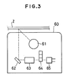
- the structure of the image sensor 60 in Fig. 2 is shown in greater detail in Fig. 3.
- the image sensor 60 comprises illumination means such as a fluorescent lamp 61, a mirror 62, reducing optical means such as a lens 63, color filters 64, and photodetector means such as an array of photodetector elements 65.
- illumination means such as a fluorescent lamp 61
- a mirror 62 reducing optical means such as a lens 63
- color filters 64 such as an array of photodetector elements 65.
- the color filters 64 transmit three different primary colors, such as yellow, magenta, and cyan, enabling these colors to be scanned separately.
- the operation of the scanning and printing apparatus in Fig. 2 is similar to the operation of the scanning and printing apparatus in Fig. 1 except that the document 2 is scanned three times, once per color.
- the signal processing circuit 52 may comprise further circuits for processing the electrical signals transmitted from the scanning means to the printing means. Processes such as edge enhancement and intensity-scale adjustment can be performed, for example, or the image can be enlarged or reduced. Reduction and enlargement processes can be carried out entirely in the signal processing circuit 52 by combining or interpolating dots. Alternatively, the signal processing circuit 52 can perform enlargement and reduction in the lateral direction, leaving enlargement and reduction in the lengthwise direction to be performed by running the motor 11 and the platen roller 44 at a faster or slower speed in the reverse direction during printing than in the forward direction during scanning.
- This scanning and printing apparatus is similar to the one in Fig. 1 except for the structure of its driving and scanning means.
- the second part comprises a second mirror 73 and a third mirror 74. These are coupled to the second wire 18 and driven in the same direction as the clamping lever 31 but at half the speed.
- Printing and scanning sequences other than the ones described can be employed.
- the first color can be simultaneously scanned and printed as the scanning means moves in one direction; then the second color can be simultaneously scanned and printed as the scanning means returns in the opposite direction.
- all scanning and printing operations can be performed separately and in the same direction, using two full reciprocating cycles for each color.
Landscapes
- Engineering & Computer Science (AREA)
- Multimedia (AREA)
- Signal Processing (AREA)
- Facsimile Scanning Arrangements (AREA)
- Electronic Switches (AREA)
- Fax Reproducing Arrangements (AREA)
Applications Claiming Priority (6)
| Application Number | Priority Date | Filing Date | Title |
|---|---|---|---|
| JP267355/88 | 1988-10-24 | ||
| JP63267355A JPH0734572B2 (ja) | 1988-10-24 | 1988-10-24 | 読取記録複合装置 |
| JP280591/88 | 1988-11-07 | ||
| JP63280591A JPH0783422B2 (ja) | 1988-11-07 | 1988-11-07 | カラー画像読取記録装置 |
| JP5491189A JPH02235672A (ja) | 1989-03-09 | 1989-03-09 | 読取記録装置 |
| JP54911/89 | 1989-03-09 |
Publications (3)
| Publication Number | Publication Date |
|---|---|
| EP0366380A2 true EP0366380A2 (de) | 1990-05-02 |
| EP0366380A3 EP0366380A3 (de) | 1991-09-25 |
| EP0366380B1 EP0366380B1 (de) | 1995-11-08 |
Family
ID=27295433
Family Applications (1)
| Application Number | Title | Priority Date | Filing Date |
|---|---|---|---|
| EP89310872A Expired - Lifetime EP0366380B1 (de) | 1988-10-24 | 1989-10-23 | Bildabtast- und Druckvorrichtung |
Country Status (3)
| Country | Link |
|---|---|
| US (1) | US4957689A (de) |
| EP (1) | EP0366380B1 (de) |
| DE (1) | DE68924754T2 (de) |
Cited By (2)
| Publication number | Priority date | Publication date | Assignee | Title |
|---|---|---|---|---|
| EP0497440A3 (en) * | 1991-01-03 | 1994-07-06 | Xerox Corp | Image copying apparatus with single read/write head carriage, providing directionally correct copies |
| WO1995026096A1 (en) * | 1994-03-22 | 1995-09-28 | Romano Conti | Improved scanning apparatus |
Families Citing this family (18)
| Publication number | Priority date | Publication date | Assignee | Title |
|---|---|---|---|---|
| US5107339A (en) * | 1990-06-25 | 1992-04-21 | Xerox Corporation | Method and apparatus for stream printing in an electronic reprographic device |
| US5321749A (en) * | 1992-09-21 | 1994-06-14 | Richard Virga | Encryption device |
| JP3231451B2 (ja) * | 1993-02-24 | 2001-11-19 | 株式会社日立製作所 | ファクシミリ装置 |
| JPH0723190A (ja) * | 1993-07-05 | 1995-01-24 | Canon Inc | ファクシミリ装置 |
| US5790279A (en) * | 1995-09-13 | 1998-08-04 | Sakellaropoulos; Spiro | Combined scanner, printer and facsimile apparatus |
| US5719404A (en) * | 1996-04-09 | 1998-02-17 | Must Systems, Inc. | Method and apparatus for calibrating the horizontal starting point of a document on a flatbed scanner |
| US6373947B1 (en) | 1996-08-26 | 2002-04-16 | Aliroo Ltd. | Document processing |
| US6704118B1 (en) | 1996-11-21 | 2004-03-09 | Ricoh Company, Ltd. | Method and system for automatically and transparently archiving documents and document meta data |
| US7602518B2 (en) * | 1996-11-21 | 2009-10-13 | Ricoh Company, Ltd. | Automatic and transparent document archiving |
| US5978477A (en) | 1996-11-21 | 1999-11-02 | Ricoh Company Limited | Automatic and transparent document archiving |
| US7170629B2 (en) * | 1998-11-13 | 2007-01-30 | Ricoh Company, Ltd. | Automatic and transparent document archiving |
| US5907413A (en) * | 1997-04-10 | 1999-05-25 | Microtek International, Inc. | Contact image sensor flat bed scanner |
| US6684368B1 (en) * | 1998-11-13 | 2004-01-27 | Ricoh Company, Ltd. | Method for specifying delivery information for electronic documents |
| JP2001253570A (ja) * | 2000-03-13 | 2001-09-18 | Canon Inc | 記録装置 |
| TW562371U (en) * | 2002-09-24 | 2003-11-11 | Veutron Corp | Carriage device of scanner |
| KR100708136B1 (ko) * | 2005-05-26 | 2007-04-17 | 삼성전자주식회사 | 화상입출력장치 및 화상입출력방법 |
| US8467530B2 (en) * | 2005-10-05 | 2013-06-18 | Kabushiki Kaisha Toshiba | System and method for encrypting and decrypting document reproductions |
| US7843611B2 (en) * | 2007-07-18 | 2010-11-30 | Kuwait University | High speed flatbed scanner comprising digital image-capture module with two-dimensional optical image photo-sensor or digital camera |
Family Cites Families (7)
| Publication number | Priority date | Publication date | Assignee | Title |
|---|---|---|---|---|
| EP0048118A3 (de) * | 1980-09-15 | 1985-01-02 | Texas Instruments Incorporated | Faksimileentwurf |
| JPS5875965A (ja) * | 1981-10-31 | 1983-05-07 | Toshiba Corp | カラ−印刷装置 |
| US4476496A (en) * | 1982-06-21 | 1984-10-09 | Image Communications Inc. | Linear motor facsimile machine |
| IT1203665B (it) * | 1983-02-10 | 1989-02-15 | Olivetti & Co Spa | Procedimento ed apparecchiatura per la riproduzione di immagini a colori |
| US4708486A (en) * | 1985-05-20 | 1987-11-24 | Kabushiki Kaisha Toshiba | Image-forming apparatus |
| JP2576508B2 (ja) * | 1987-06-11 | 1997-01-29 | 三菱電機株式会社 | サ−マルプリンタ |
| JPH0818574B2 (ja) * | 1989-05-29 | 1996-02-28 | 株式会社小松製作所 | ハイドロスタティック旋回制御装置 |
-
1989
- 1989-10-17 US US07/422,690 patent/US4957689A/en not_active Expired - Fee Related
- 1989-10-23 DE DE68924754T patent/DE68924754T2/de not_active Expired - Fee Related
- 1989-10-23 EP EP89310872A patent/EP0366380B1/de not_active Expired - Lifetime
Cited By (2)
| Publication number | Priority date | Publication date | Assignee | Title |
|---|---|---|---|---|
| EP0497440A3 (en) * | 1991-01-03 | 1994-07-06 | Xerox Corp | Image copying apparatus with single read/write head carriage, providing directionally correct copies |
| WO1995026096A1 (en) * | 1994-03-22 | 1995-09-28 | Romano Conti | Improved scanning apparatus |
Also Published As
| Publication number | Publication date |
|---|---|
| EP0366380A3 (de) | 1991-09-25 |
| EP0366380B1 (de) | 1995-11-08 |
| DE68924754T2 (de) | 1996-06-27 |
| DE68924754D1 (de) | 1995-12-14 |
| US4957689A (en) | 1990-09-18 |
Similar Documents
| Publication | Publication Date | Title |
|---|---|---|
| US4957689A (en) | Scanning and printing apparatus | |
| JP4140287B2 (ja) | 画像読み取り装置、原稿送り装置、および原稿読み取り方法 | |
| EP0465216B1 (de) | Kompakter Lese-/Druck-Abtaster | |
| US4920421A (en) | Simultaneous read/write copier | |
| US7551331B2 (en) | Image reading apparatus and image reading method | |
| EP0465213B1 (de) | Ein- und Ausgangsabtaster | |
| US5032922A (en) | Platen accessory for portable copier | |
| EP0497440A2 (de) | Bildkopiergerät mit einfachem Lese- und Schreibkopfschlitten zur Erstellung richtungsgerechter Kopien | |
| EP0465209B1 (de) | Abtaster mit Mitteln zur Registrierung von Vorlagen und Kopieblättern | |
| JPS58173963A (ja) | 2色複写機 | |
| US5095372A (en) | Combined copying machine and facsimile scanner and method | |
| EP0066625A1 (de) | Kopiermaschine vom typ mit thermischem druck | |
| JP2698466B2 (ja) | 画像複写装置 | |
| JP2872261B2 (ja) | 複写装置 | |
| JPS63120660A (ja) | 記録装置 | |
| JPH02283167A (ja) | 複写装置 | |
| JPH02235672A (ja) | 読取記録装置 | |
| JPH09211902A (ja) | 記録装置 | |
| JPH04304065A (ja) | 画像形成装置 | |
| JPH08104034A (ja) | 記録装置 | |
| JPH0197969A (ja) | 画像形成装置 | |
| JPS621359A (ja) | 画像形成装置 | |
| JPH07107242A (ja) | 複合機 | |
| JPH04302574A (ja) | 画像形成装置 | |
| JPS63294169A (ja) | 画像形成装置 |
Legal Events
| Date | Code | Title | Description |
|---|---|---|---|
| PUAI | Public reference made under article 153(3) epc to a published international application that has entered the european phase |
Free format text: ORIGINAL CODE: 0009012 |
|
| AK | Designated contracting states |
Kind code of ref document: A2 Designated state(s): DE FR GB |
|
| 17P | Request for examination filed |
Effective date: 19901219 |
|
| PUAL | Search report despatched |
Free format text: ORIGINAL CODE: 0009013 |
|
| AK | Designated contracting states |
Kind code of ref document: A3 Designated state(s): DE FR GB |
|
| 17Q | First examination report despatched |
Effective date: 19931112 |
|
| GRAA | (expected) grant |
Free format text: ORIGINAL CODE: 0009210 |
|
| AK | Designated contracting states |
Kind code of ref document: B1 Designated state(s): DE FR GB |
|
| REF | Corresponds to: |
Ref document number: 68924754 Country of ref document: DE Date of ref document: 19951214 |
|
| ET | Fr: translation filed | ||
| PLBE | No opposition filed within time limit |
Free format text: ORIGINAL CODE: 0009261 |
|
| STAA | Information on the status of an ep patent application or granted ep patent |
Free format text: STATUS: NO OPPOSITION FILED WITHIN TIME LIMIT |
|
| 26N | No opposition filed | ||
| REG | Reference to a national code |
Ref country code: GB Ref legal event code: 746 Effective date: 19971202 |
|
| REG | Reference to a national code |
Ref country code: FR Ref legal event code: D6 |
|
| PGFP | Annual fee paid to national office [announced via postgrant information from national office to epo] |
Ref country code: FR Payment date: 19981009 Year of fee payment: 10 |
|
| PGFP | Annual fee paid to national office [announced via postgrant information from national office to epo] |
Ref country code: GB Payment date: 19981023 Year of fee payment: 10 |
|
| PGFP | Annual fee paid to national office [announced via postgrant information from national office to epo] |
Ref country code: DE Payment date: 19981103 Year of fee payment: 10 |
|
| PG25 | Lapsed in a contracting state [announced via postgrant information from national office to epo] |
Ref country code: GB Free format text: LAPSE BECAUSE OF NON-PAYMENT OF DUE FEES Effective date: 19991023 |
|
| GBPC | Gb: european patent ceased through non-payment of renewal fee |
Effective date: 19991023 |
|
| PG25 | Lapsed in a contracting state [announced via postgrant information from national office to epo] |
Ref country code: FR Free format text: LAPSE BECAUSE OF NON-PAYMENT OF DUE FEES Effective date: 20000630 |
|
| PG25 | Lapsed in a contracting state [announced via postgrant information from national office to epo] |
Ref country code: DE Free format text: LAPSE BECAUSE OF NON-PAYMENT OF DUE FEES Effective date: 20000801 |
|
| REG | Reference to a national code |
Ref country code: FR Ref legal event code: ST |