EP0366383B1 - Commutateur de feux de véhicule avec appel de phare - Google Patents
Commutateur de feux de véhicule avec appel de phare Download PDFInfo
- Publication number
- EP0366383B1 EP0366383B1 EP89310878A EP89310878A EP0366383B1 EP 0366383 B1 EP0366383 B1 EP 0366383B1 EP 89310878 A EP89310878 A EP 89310878A EP 89310878 A EP89310878 A EP 89310878A EP 0366383 B1 EP0366383 B1 EP 0366383B1
- Authority
- EP
- European Patent Office
- Prior art keywords
- carrier
- terminal
- flash
- pass
- contactor
- Prior art date
- Legal status (The legal status is an assumption and is not a legal conclusion. Google has not performed a legal analysis and makes no representation as to the accuracy of the status listed.)
- Expired - Lifetime
Links
Images



Classifications
-
- H—ELECTRICITY
- H01—ELECTRIC ELEMENTS
- H01H—ELECTRIC SWITCHES; RELAYS; SELECTORS; EMERGENCY PROTECTIVE DEVICES
- H01H13/00—Switches having rectilinearly-movable operating part or parts adapted for pushing or pulling in one direction only, e.g. push-button switch
- H01H13/50—Switches having rectilinearly-movable operating part or parts adapted for pushing or pulling in one direction only, e.g. push-button switch having a single operating member
- H01H13/56—Switches having rectilinearly-movable operating part or parts adapted for pushing or pulling in one direction only, e.g. push-button switch having a single operating member the contact returning to its original state upon the next application of operating force
- H01H13/562—Switches having rectilinearly-movable operating part or parts adapted for pushing or pulling in one direction only, e.g. push-button switch having a single operating member the contact returning to its original state upon the next application of operating force making use of a heart shaped cam
-
- B—PERFORMING OPERATIONS; TRANSPORTING
- B60—VEHICLES IN GENERAL
- B60Q—ARRANGEMENT OF SIGNALLING OR LIGHTING DEVICES, THE MOUNTING OR SUPPORTING THEREOF OR CIRCUITS THEREFOR, FOR VEHICLES IN GENERAL
- B60Q1/00—Arrangement of optical signalling or lighting devices, the mounting or supporting thereof or circuits therefor
- B60Q1/02—Arrangement of optical signalling or lighting devices, the mounting or supporting thereof or circuits therefor the devices being primarily intended to illuminate the way ahead or to illuminate other areas of way or environments
- B60Q1/04—Arrangement of optical signalling or lighting devices, the mounting or supporting thereof or circuits therefor the devices being primarily intended to illuminate the way ahead or to illuminate other areas of way or environments the devices being headlights
- B60Q1/14—Arrangement of optical signalling or lighting devices, the mounting or supporting thereof or circuits therefor the devices being primarily intended to illuminate the way ahead or to illuminate other areas of way or environments the devices being headlights having dimming means
- B60Q1/1446—Arrangement of optical signalling or lighting devices, the mounting or supporting thereof or circuits therefor the devices being primarily intended to illuminate the way ahead or to illuminate other areas of way or environments the devices being headlights having dimming means controlled by mechanically actuated switches
- B60Q1/1453—Hand actuated switches
- B60Q1/1461—Multifunction switches for dimming headlights and controlling additional devices, e.g. for controlling direction indicating lights
- B60Q1/1469—Multifunction switches for dimming headlights and controlling additional devices, e.g. for controlling direction indicating lights controlled by or attached to a single lever, e.g. steering column stalk switches
Definitions
- This invention relates to automotive switching systems for electrical headlights and the like, and more particularly to a beam selection switch for switching to and from high and low beams for the headlights, and even more particularly to one in which there is included a "flash-to-pass" switch.
- a switch is particularly useful in the automotive field, in which a headlight beam selector switch having a momentary "flash-to-pass" position is required for quickly and easily warning other vehicles of the intent to pass or of the existence of a dangerous situation.
- Vehicle headlight systems typically allow a driver to choose between a low beam mode, a high beam mode, or, more recently, a "flash-to-pass” mode.
- a “flash-to-pass” mode refers to a driver momentarily energizing the high beam circuit in order to give warning to other drivers of an intention to pass or of a potential hazard. This is typically accomplished by urging a beam selector stalk mounted on the steering column toward the steering wheel and holding it down for a few seconds, and then releasing it, causing the headlights to momentarily "flash” in its high beam mode.
- leaf spring type designs typically employed rocker, over-centering, or rotary devices, resulting in unacceptable stack-up dimensions.
- An additional problem with the prior art leaf spring contact style switches is that they were sometimes difficult to assemble.
- drivers typically desire that the lever control stalk used to actuate the "flash-to-pass" mode of the headlights have the same "home” position, usually about six to eight millimeters below the steering wheel, regardless of whether the headlights are in their high beam or low beam selected modes.
- Such consistent, particular positioning of the end of the control lever stalk allows the driver to easily engage the end of the stalk with the associated fingers of one hand to quickly and easily actuate the "flash-to-pass” mode or, alternatively, to select or de-select the high beam mode, as desired, all with similar motions and all starting at the same "home” point.
- the present invention overcomes the above shortcomings in the existing art, as well as achieving the "home" lever positioning desired in the marketplace. Furthermore, the switch systems disclosed herein require low functional effort due to a fewer number of parts, lower spring rates, and the reduction of the frictional surface area(s) to be overcome in actuating the switch. Additionally, the present invention allows for the beam selector stalk to have a "short throw” and to return to a constant "home position" with respect to the steering wheel, regardless of which detent position (high or low beam) the switch may happen to have been in.
- a still further object is to provide such a switching system in which the user actuating member is returned to the same "home” position, regardless of the fully detented mode it is in.
- the present invention is thus directed to a "hi/lo" headlight beam selector switch, combined with a “flash-to-pass” mode, in which the various switching components undergo linear travel, in which at least one carrier carrying at least one contactor having multiple contact dimples selectively interconnect various elongated and configured pads during the linear movement of the carrier(s).
- These linear movement(s) control(s) a power feed to the high beam for the "flash-to-pass” mode, while preferably maintaining the "lo" beam “on,” and controls the selection of the "hi" beam(s) when the switch components are moved to their furthermost position.
- the carrier In the "hi" beam selection the carrier is latched down in its furthermost position.
- the linear switch will be actuated by a pivoting control lever stalk mounted on the steering wheel column, which preferably is pulled toward the driver to actuate the switch, causing the internal switching elements to be moved down with respect to the configured or profiled, elongated, electrical contact pads.
- the switch is positioned on the opposite side of the lever pivot axis from the driver engageable part of the lever.
- two separate power feed lines are used for the switch, making a total of four terminals, one feed line for the "flash-to-pass” operation and one for the beam selector operation, and in which two, separable, linearly moveable carriers are used.
- a lower carrier is used for beam selection, which lower one is latched down in place when "hi" beam mode is selected, and an upper carrier is used for "flash-to-pass,” which is always free to move back up to its "home” position, when the driver releases the control lever.
- Two separate return springs are used, a stronger one positioned below the lower, beam selector carrier and a weaker one associated with the upper "flash-to-pass" carrier, positioned, for example, between the two carriers. This allows the two carrier to move together, when the "hi" beam is not selected (during which the lower carrier is unlatched), but also causes the upper carrier to return under the action of the weaker return spring, when the lower carrier is latched into place when the "hi" beam mode has been selected.
- This latching and unlatching action preferably is achieved by the use of a detent spring having a projecting tip which co-acts with an asymmetrical "heart shaped" cam, about which the spring tip moves during a full cycle of operation.
- a detent spring can be mounted on the terminal block enclosure stucture with the cam surface provided on the latchable carrier, or vice versa.
- a single, common power feed line or terminal is used, allowing the use of a single, latchable carrier carrying a single contactor with three contact dimples.
- This embodiment would be particularly useful in those headlight systems, which are desired or required to be "on,” not only for night time travel, but in daylight as well.
- the present invention is directed to a linear, push-push (or pull-pull) type switch, wherein, in the preferred embodiments, an asymmetrical "heart shaped" cam is engaged by a spring member to provide predetermined positioning and holding of a longitudinally movable carrier carrying spring-loaded movable contacts traveling along and over adjacent, longitudinal extended contact pads or terminals, in order to open or close appropriate circuits, including a momentarily closed "flash-to-pass" circuit, as well as high beam/low beam selection switching.
- Figure 1 is an isometric, exploded view of a first exemplary embodiment of the switching system of the present invention, showing its various elements in exploded array, including two, separable carriers, an upper or primary one carrying the "flash-to-pass" contacts and a lower or secondary one separately carrying the high/low beam selector contacts for a four terminal system.
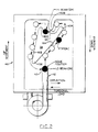
- Figure 2 is a detailed, close-up, frontal view of the longitudinally moveable beam selector carrier element of Figure 1, showing the relative travel of the engaging tip of the detent spring as it moves up, along and around the asymmetrical "heart” shaped cam as the carrier is moved longitudinally down (and up) under the various possible switching actions of the driver moving the lever stalk (not illustrated).
- Figure 3A is a detailed, close-up, rear view of the beam selector carrier of Figures 1 & 2
- Figure 3B is a "horizontal" cross-sectional view of the beam selector carrier, taken along section line 3B-3B of Figure 3A .
- Figure 4 is an isometric, exploded view of a second exemplary embodiment of the switching system of the present invention, showing its various elements in exploded array, similar to the embodiment of Figure 1 , but with the separate beam selector contactor and the "flash-to-pass" contactor and their two associated springs of the embodiment of Figure 1 combined into one composite contactor with three contact dimples and only one associated spring, and with the two carriers and their two associated, different strength springs of the embodiment of Figure 1 combined into one carrier with one spring having two portions having different strength portions (or alternatively two nested springs), for a three terminal system.
- Figure 5 is a front, close-up view of the three longitudinally extended, profiled contact pads of the embodiment of Figure 4 , showing the various circuit making positions of the switching system, as the single contactor with its three contact dimples is moved down across the faces of the contact pads.
- Figure 6 is a rear, close-up view of an alternate, single, floating contactor with three dimples substantively identical to the floating contactor of Figure 4 , but having a triangular configuration in place of the rectangular configuration of the contactor of Figure 4 .
- Figure 7 is a schematic of the basic exemplary automotive circuitry with which the embodiment of Figure 1 of the switching system of the present invention can be used.
- a first exemplary embodiment 1 of the switching system of the present invention includes a terminal block 2 , an upper, "flash-to-pass" carrier 24 , a lower, beam selector carrier 46 and a cover 64 , along with associated return springs, floating contactors and associated, appropriately profiled, terminal pads or strips, as described more fully below.
- the carriers 24 & 46 are moved linearly up and down under the action(s) typically of the vehicle driver causing the floating contactors carried by the carriers to appropriately make and break circuits associated with the terminal pads, all again as is explained more fully below.
- the terminal block 2 includes, for example, four externally extending, flat, terminal connectors 4, 6, 8 & 10 for electrically interconnecting in the switching process the "flash-to-pass" feed line ( 4 ), the "hi beam” line ( 6 ), the “low beam” line ( 8 ) and the beam selector feed line ( 10 ), respectively, to the appropriate components and circuitry of the vehicle (note Fig. 7 ).
- Each terminal connector is associated with and electrically connected to an internal, appropriately profiled or configured and located, longitudinally extended, terminal contact strip or pad 4A, 6A, 8A & 10A , respectively, over which floating contactors 52 & 38 for the beam selector and the "flash-to-pass," respectively, pass for appropriately making and breaking the various electrical circuits involved.
- the terminal block 2 includes four side walls or panels, namely the opposed side panels 12 & 14 and the opposed bottom and upper panels 16 & 18 , which together with the base upon which the contract strips 4A-10A are located, form a box-like enclosure for the remaining elements of the switching system.
- the upper panel 18 has a "cut-out" portion 20 to allow the upper, "flash-to-pass” carrier's projection 26 to extend out of the interior of the terminal block 2 , with the side edge sections 18A of the upper panel 18 mating with like configured, side shoulders 24A on the upper part of the "flash-to-pass” carrier 24 .
- the "flash-to-pass" carrier 24 serving as an upper carrier, has an exterior projection or post 26 fixedly mounted on the upper bridging portion 28 .
- the post 26 serves as a switch actuation member, which can be engaged or contacted from the exterior of the terminal block 2 to cause the internal components of the terminal block 2 to be linearly moved from switch mode to switch mode.
- the actuation member 26 can be designed to have positive connection means, such as for example, a slotted end, for connection to an external, supplemental actuation member, such as for example a pivoting control lever stalk mounted on the steering column of the steering wheel.
- the switch actuation member 26 could be "totally contained within” the confines of the closed terminal block with the external, supplemental actuation member extending into the confines to engage or be connected to the then internal actuating member.
- the upper portion 28 terminates at its ends in two downwardly extending, opposed, parallel, side legs 30 & 32 .
- the inwardly facing sides of the legs 30 & 32 include guide surfaces or keys 34 & 36 , respectively, into or onto which mating side projections 35 & 37 , respectively, of the beam selector carrier 46 fit, the surfaces providing interfacing guiding, sliding surfaces for the two carriers.
- the two carriers 24 & 48 travel together in their initial “downward” travel, the upper carrier 24 thereafter may be called upon to separately travel back up, while the lower carrier 48 remains “locked” or latched down in place when the high beam mode of the switch is selected, as will be explained more fully below.
- the flat, face-to-face contacting surfaces 34 & 35 and 36 & 37 between the two carriers allow them to easily slide pass one another, when relative movement of them is called for, while maintaining their relative alignment together about their common longitudinal axes.
- the "flash-to-pass" carrier 24 carries on its back side a floating contactor, including a “flash-to-pass” contactor spring 42 and a floating “vertically” aligned, contactor element 38 with its rearwardly directed contact dimples 40 & 41 .
- the proximal end of the spring 42 is located within a cylindrical chamber (not illustrated but substantively identical to the one described for the other carrier with reference to Figures 3A & 3B ) located on the back-side of the leg 32 , while the proximal tips of the side legs of the contactor 38 ride in slots (again not illustrated but substantively identical to the ones described for the other carrier with reference to Figures 3A & 3B ) on the back-side of the leg 32 .
- the contactor 38 When the switching system is fully assembled with the cover 65 connected to the terminal block 2 , with the internal elements contained between them, the contactor 38 "floats" and is sandwiched between the back-side of the upper carrier 24 and the front, terminal pad side of the block 2 ; with the spring 42 causing it to biased in floating fashion with the contact dimples 40 & 41 traveling up and down along the vertical dimple tracking line 22A against the base of the block 2 , as the upper carrier moves up and down.
- the beam selector carrier 46 serving as a lower carrier, includes top and bottom, cylindrical openings or chambers 47 & 49 , respectively, which are sized to accommodate the proximal ends of the upper and lower spring returns 44 & 48 , respectively.
- the other end of the upper return spring 44 fits into a like cylindrical chamber (not illustrated) in the underside of the bridging section 28 of the upper carrier 24 , while the other end of the lower return spring 48 rests against the inner side of the panel 16 of the terminal block 2 , when the switching system 1 is completely assembled.
- the upper return spring 44 is relatively "weak,” while the lower return spring 48 is relatively “strong.” As a result, when the carriers are in their upper most positions, the lower return spring 48 overcomes the resistance of the upper return spring 44 , keeping the two carriers in contact together for common movement with each other, as if they were of a common integral construction. On the other hand, when the lower carrier 46 is "locked” or latched down in its high beam position, in an action explained more fully below, the upper return spring 44 causes the upper carrier 24 to return back up to its uppermost position, when the driver releases the lever stalk.
- a back-side cylindrical opening 53 is provided to accommodate the proximal end of the beam selector spring 54 for floating the beam selector contactor 52 on the back side of the beam selector carrier 46 .
- Vertical slots 55 are provided on the back-side, into which are received the side legs 52A of the contactor 52 . It should be understood that the mounting details for the contactors 38 & 52 are not part of the present invention, and they can be mounted in any effective, desirable way.
- the interfacing structures and "floating" operation of the "horizontal" beam selector contactor 52 is substantively identical to that described above with respect to the vertical, "flash-to-pass” contactor 38 , except for their relative orientation, with the beam selector contact dimples 50 & 51 bridging across and riding along the contact dimple lines 22B & 22C , respectively.
- an asymmetrical "heart-shaped" cam 56 is provided within the center structure of the beam selector carrier 46 , which cam has a confined top plateau area 60 located between two, somewhat offset, downwardly extending sides 61A & 61B terminating in upwardly projecting tips 60A & 60B .
- a leftwardly offset bottom tip area 58 is provided at the bottom of the cam 56 .
- An engaging detent spring 62 having a distal end tip 63 , is configured to co-act with the peripheral edges and projecting tips of the heart-shaped cam 56 , as it moves about and around the periphery of the cam in a counter-clockwise direction as a result of the various possible movements of the lower beam selector carrier 46 , in an operation explained more fully below.
- the terminal block cover 64 includes on its interior or backside two spaced, spring holding means 65A & 65B for the detent spring 62 , into which the lower circular portion and the lower terminal tip leg of the spring 62 are held, respectively, holding the lower part of the detent spring in a fixed position relative to the cover and the beam selector carrier 46 .
- the upper, longer leg of the detent spring 62 is able to move laterally (left and right) with respect to the cover 64 and the beam selector carrier 46 . It will move to the right from its "natural" position (as illustrated in full line in Fig.
- the detent spring 62 and the cam 56 are designed to latch and control the relative movements of the lower carrier 46 with respect to the over-all terminal body or enclosure 2/64 .
- the spring 62 could be mounted on the carrier 46
- the cam 56 could be provided on the cover or other static part of the over-all terminal enclosure or structure.
- the cover 64 also includes orthogonally extended, snap legs 66 for snap latching the cover onto the terminal block 2 .
- the cover 64 When the cover 64 is snapped onto the block 2 , it closes off the interior between them (except for the upper "cut out” portion 20 ) and holds all the interiorly contained, appropriately assembled elements of the switching system 1 together under spring compression created in the vertical or longitudinal and orthogonal directions by the return spring 48 and the contactor springs 42 & 54 , respectively.
- the "home” position of the switch as represented by the position of the detent spring 62 , is illustrated by the spring in full line of in Figure 2 with the darken tip 63 being marked as the "HOME POSITION,” and is the first fully detented position of low beam mode of the switch 1.
- the beam selector contact dimples 50 & 51 are located at the upper portions of the pad strips 8A & 10A , bridging across them, electrically interconnecting the low beam terminal 8 to the beam selector feed terminal 10 .
- the floating contactors 38 & 52 begin to move longitudinally down with respect to the terminal block 2 , causing the "flash-to-pass" contact dimples 40 & 41 to move down along the dimple tracking line 22A and the beam selector contact dimples 50 & 51 to move down along dimple tracking lines 22B & 22C , respectively.
- the detent spring tip 63 moves relatively up and over to the right, as it is moved by the downwardly moving, offset right wall of the cam 56 (see Fig. 2 ).
- the beam selector contacts 50 & 51 continue to bridge across and electrically interconnect terminal contact pads 8A & 10A and hence the low beam terminal 8 to the beam selector feed terminal 10 , maintaining that part of the circuit closed.
- the "flash-to-pass" contact dimples 40 & 41 merely ride down along the pad 6A , effectively being electrically neutral with respect to the light switching circuitry.
- the two pads 4A & 6A are bridged across, electrically interconnecting the "flash-to-pass" feed terminal 4 to the high beam terminal 6 in the circuitry.
- This causes the high beams of the vehicle headlights to be flashed "on” and is represented by the darkened circle representing the relative position of the detent spring tip 63 marked as "FTP ON" in Figure 2 , while the low beam line to feed line interconnection is maintained.
- the carriers are further moved down against the lower return spring 48 .
- the beam selector contact dimple 50 moves off of the low beam pad 8A and onto the laterally projecting, side portion 6B of the high beam pad 6A , causing the low beam switch to the feed terminal 10 to be opened and the high beam switch to the feed terminal 10 to be closed.
- the tip 63 of the detent spring 62 moves up and over the right side, projecting tip 60A , at which point the torsional load in the spring causes the tip 63 to then move over toward the center against the downwardly projecting center stop 60B .
- the lower return spring 48 causes the lower carrier 46 to move up an exemplary one millimeter until the upper plateau 60 of the cam hits the orthogonally projecting spring tip 63 , preventing any further upward movement of the carrier 46 .
- the spring tip 63 is able to clear under the central stop 60C and moves left across the plateau 60 , until it hits the projecting tip on the left side of the cam 56 , which is to the left of the central stop 60B .
- the beam selector carrier is latched into its high beam mode.
- the driver again pulls the stalk lever, applying force down against the upper carrier 24 until it bottoms out at an exemplary five millimeters of travel, that is, until the bottom surface of the lower carrier 46 comes into contact with the lower panel of the terminal block 2 . While this occurs, toward the end of the travel, the detent spring tip 63 moves up and over the left side projecting tip 60C , unlatching the lower carrier from the orthogonally projecting spring tip. The lower carrier is then free to be pushed up by the lower return spring 48 , causing the detent spring tip 63 to be moved right, as it follows the relative path shown to the left of the offset, left wall 61B of the cam 56 .
- the switch 1 has been put through one complete duration of a cycle, which of course can be repeated as often as desired.
- FIG. 4 & 5 An alternative exemplary embodiment for the switching system of the present invention is illustrated in Figures 4 & 5, in which the two separable carriers of the embodiment of Figure 1 are replaced by a single movable carrier 124/146 carrying a single "floating" contactor 138/152 working in conjunction with three terminal strip pads 104A/110A, 106 & 108.
- the terminal block 102 combines them into one feed terminal 104/110.
- a single spring 144/148 could be used having, if so desired, two sections differing in strength or having different spring constants, or, as illustrated generally in Figure 4, two separate springs 144 & 148, nested one (144) inside the other (148).
- the weaker one should extend above the stronger one, allowing the user to feel a lesser resistance in the initial "flash-to-pass" travel, but a greater resistance as the high beam selector travel is beginning and is traversed. This varying resistance, tactile feed back, through its "feel,” guides the user as to the mode the switching control lever is being put in.
- a separate "weak” spring could be used to separately return the lever arm stalk to its "home” position, when the single carrier 124/146 is latched down in position, isolating the lever stalk from the force(s) of the return spring(s) located below the carrier.
- This separate, relatively “weak” spring could be provided up at the top of the carrier in association with, for example, the post 126 and work in conjunction with the exterior of the terminal block 2 , or even be integrated into the control lever actuation arm itself.
- the "weak" spring would be exercising its biasing force in a pulling up, rather than a pushing up manner, while in the second it could be either pushing or pulling depending on how it was connected to and associated with the control lever stalk. In either event it is desirable and preferable that the biasing force(s) be applied either directly or indirectly to the lever arm, in a way that causes it to always return to the same "home” position when pressure on it from the user is removed, regardless of the switch mode that the switch 101 is in. (These same alternate approaches are applicable to the relatively "weak” spring 44 of the embodiment of Figure 1 .)
- the combined contactor 138/152 includes on its back side three contact dimples D1 , D2 & D3 .
- the first two ( D1 & D2 ) are vertically aligned and spaced dimples, which together travel along dimple tracking line 122E
- one ( D3 ) is a laterally spaced dimple centrally located vertically between the other two.
- the third dimple D3 travels along dimple tracking line 122D always in contact with the power feed pad 104A/110A .
- the low beam pad 108A has a laterally projecting, side portion 108B , which extends over above the upper, longitudinal extension of the adjacent, high beam pad 106A .
- dimple D3 is always in contact with the feed pad 104A/110A and at least one of the other two dimples is always in contact with either the low or high beam pads 108A, 106A, no "black out” can occur when one of the vertically aligned dimples D1 or D2 is passing through the space between adjacent terminal pads, as it travels from one beam pad to the next.
- the longitudinal dimension of the dimples could be dimensioned to be larger than the separation distance between the longitudinally spaced pads across which they travel.
- the detent spring 162 and its orthogonally projecting tip 163 co-act and move, in relationship to the periphery of the asymmetrical "heart" shaped cam 156, In like fashion to the spring 62 and cam 56 of Figure 1.
- FIG. 6 An alternative embodiment for the single floating contactor is shown in Figure 6.
- the triangularly configured contactor 138/152A carries on its back side three similar contact dimples D 1A , D 2A & D 3A , but with the feed contact dimple D 3A being larger in size to handle the double flow of current when the contactor is in the intermediate, "flash-to-pass" position.
- the "flash-to-pass" power feed terminal 4 is connected to one side of the vehicle's power source, typically a twelve volt DC battery 70 , while the beam selector power feed terminal 10 also is connected to the same side of the vehicle's power source, but only after passing through the main headlight switch 71 .
- the main headlight switch 71 is typically a pull-push switch combined with a rotary switch (or simply a rocker switch), usually mounted on the dashboard, for turning the headlights "on” and "off.
- the "hi" beam and the “lo” beam terminals 6 & 8 are connected to the other side of the vehicle power source through the high beam and the low beam filaments 72 & 73 , respectively, of the vehicle headlight(s).
- the "flash-to-pass” carrier movement causeds the contactor dimples 40 & 41 to bridge the pads 4A & 6A (and hence the terminals 4 & 6 )
- the high beams are flashed "on” regardless of the state of the main headlight switch 71 .
Landscapes
- Engineering & Computer Science (AREA)
- Mechanical Engineering (AREA)
- Switches With Compound Operations (AREA)
- Lighting Device Outwards From Vehicle And Optical Signal (AREA)
- Push-Button Switches (AREA)
Claims (13)
- Système commutateur de phares muni d'un mode "appel de phares", comprenant :
un bloc de connexion (2 ; 102) présentant une plaquette à pistes de contact ;
au moins trois pistes profilées de raccordement (4A, 6A, 8A, 10A ; 106, 108, 104/110) s'étendant longitudinalement, situées sur ladite plaquette à pistes de contact, et dont au moins l'une (6A ; 108A) comporte une région latérale (6B ; 108B) qui s'étend latéralement au-delà de l'axe longitudinal de l'étendue de l'une (8A ; 106A) des autres pistes ;
une structure de support, dotée d'au moins un support (46 ; 124/146) mobile linéairement et comprenant- un côté de raccordement aux pistes de contact,- une région supérieure, et- une région s'étendant vers le bas, ladite région s'étendant vers le bas présentant une pièce de verrouillage, ledit support (46 ; 124/146) étant logé à mouvement linéaire dans ledit bloc de connexion (2 ; 102), et étant verrouillable provisoirement dans une position abaissée sélectionnée "feux de route" ;une pièce de commutation (26 ; 126) associée à ladite structure de support, et dimensionnée et positionnée de manière à être mise en contact à partir de l'extérieur dudit bloc de connexion (2 ; 102), pour provoquer un actionnement dudit bloc de connexion (2 ; 102) depuis l'extérieur, et pour provoquer un mouvement descendant dudit support (46 ; 124/146) jusqu'à sa position abaissée sélectionnée "feux de route" ;
une structure (38, 52 ; 138/152) de mise en contact du commodo et de l'appel de phares, présentant au moins trois zones distinctes (40, 41, 50, 51 ; D1, D2, D3) de contact électrique supportées par ladite structure, et positionnées et dimensionnées pour appliquer un contact coulissant contre lesdites pistes profilées de raccordement (4A, 6A, 8A, 10A ; 106, 108, 104/110) lorsque ledit support est déplacé linéairement le long de ladite plaquette à pistes de contact, provoquant ainsi une interconnexion électrique de combinaisons différentes desdites pistes (4A, 6A, 8A, 10A ; 106, 108, 104/110), par lesdits points de contact (40, 41, 50, 51 ; D1, D2, D3), en association avec ladite structure (38, 52 ; 138/152) de mise en contact ;
des moyens (52A, 42, 54) de montage de la structure de mise en contact, assurant le montage de ladite structure (38, 52 ; 138, 152) de mise en contact du commodo et de l'appel de phares, sur ledit côté de raccordement aux pistes de contact de ladite structure de support, en direction desdites pistes profilées de raccordement ;
une structure associée de verrouillage (56, 62 ; 156, 162) coopérant avec ledit support (46 ; 124/146) et avec ledit bloc de connexion (2 ; 102), et apte à provoquer un verrouillage dudit support vers le bas, dans sa position abaissée sélectionnée "feux de route", et un déverrouillage lorsque ladite structure d'actionnement (56, 62 ; 156, 162) est cycliquement animée d'un nouveau mouvement descendant, jusqu'à la position sélectionnée "feux de route" ; et
des moyens (48 ; 144, 148) de sollicitation du support du commodo, exerçant un effet de rappel, associés audit support et agissant sur le positionnement linéaire longitudinal desdites zones de contact du commodo, par rapport auxdites pistes profilées de raccordement, à l'écart de ladite position de verrouillage et en direction de leurs positions de repos. - Système commutateur de phares, selon la revendication 1, englobant :
au moins quatre pistes de contact situées sur ladite plaquette et comprenant- une piste (10A) d'alimentation en puissance du commodo,- une piste (6A) "feux de route",- une piste (8A) "feux de croisement", et- une piste distincte (4A) d'alimentation en puissance de l'appel de phares ;et dans lequel ladite structure de support comporte par ailleurs :
un second support supérieur mobile (24), muni d'un côté de raccordement et placé au-dessus dudit premier support (46), ledit second support (24) étant associé audit premier support (46), indépendamment duquel il est cependant mobile vers le haut dans le sens longitudinal ;
un contacteur distinct (52) du commodo, sur lequel se trouvent au moins deux zones de contact (51, 50), et qui est supporté par ledit premier support ;
des moyens distincts (52A, 54) de montage du contacteur du commodo, assurant le montage dudit contacteur (52) du commodo sur ledit côté raccordement dudit premier support (46), et comprenant un moyen de sollicitation (54) poussant ledit contacteur (52) du commodo en direction desdites pistes profilées de raccordement (4A, 6A, 8A, 10A) ;
un contacteur distinct (38) de l'appel de phares, sur lequel se trouvent au moins deux zones de contact (40, 41) et qui est supporté par ledit second support supérieur (24) ; et
un moyen distinct (42) de montage du contacteur de l'appel de phares, assurant le montage dudit contacteur de l'appel de phares sur ledit côté raccordement dudit second support, et comprenant un moyen de sollicitation (42) poussant ledit contacteur (38) de l'appel de phares en direction desdites pistes profilées de raccordement (4A, 6A, 8A, 10A). - Système commutateur de phares, selon la revendication 2, dans lequel ladite région s'étendant vers le bas présente également :
des surfaces coulissantes (35, 37) s'étendant longitudinalement, situées en vis-à-vis de surfaces de coulissement (34, 36) s'étendant longitudinalement et ménagées sur ledit second support (24), entretenant ainsi l'alignement relatif desdits supports, autour de leurs axes longitudinaux communs, lorsque le second support (24) se déplace vers le haut par rapport audit premier support (46) alors que ledit premier support (46) occupe sa position verrouillée. - Système commutateur de phares, selon la revendication 2, englobant en outre :
un moyen distinct (44) de sollicitation du support de l'appel de phares, exerçant un effet de rappel, associé audit second support (24) et agissant, en permanence,sur le positionnement longitudinal desdits points de contact (40, 41) de l'appel de phares par rapport auxdites pistes profilées de raccordement (4A, 6A, 8A, 10A), en direction de leurs positions de repos, indépendamment de l'agencement dudit premier support (46). - Système commutateur de phares, selon la revendication 2, dans lequel :
ledit moyen distinct (44) de sollicitation du support de l'appel de phares, exerçant un effet de rappel, est un ressort présentant une force inférieure à celle dudit moyen (48) de sollicitation du support du commodo, exerçant un effet de rappel. - Système commutateur de phares, selon la revendication 1, dans lequel ladite structure associée de verrouillage (56, 62 ; 156, 162), coopérant avec ledit premier support (46 ; 124/146) et avec ledit bloc de connexion (2), comprend en outre :
une came encrantable (56 ; 156) munie d'une surface irrégulière ceinturant intégralement la came avec un décalage vers l'un des côtés de l'axe médian de ladite came, s'étendant longitudinalement ; et
un ressort de détente (62 ; 162) pourvu d'une région (63 ; 163) de venue en prise avec la came encrantable, qui coopère avec ladite surface irrégulière lorsqu'elle se déplace autour de ladite came (56 ; 156), ledit ressort de détente (62 ; 162) verrouillant ledit premier support (46 ; 124/146) en position basse lorsqu'il s'engage et est retenu à l'intérieur de la zone supérieure de ladite came, lesdites pistes profilées de raccordement (4A, 6A, 8A, 10A ; 106, 108, 104/110), ledit appel de phares et les zones de contact (40, 41, 51, 52, D1, D2, D3) du commodo étant positionnnés de manière à sélectionner une première position "feux de croisement" totalement encrantée, une position provisoire "appel de phares" et une seconde position "feux de route" totalement encrantée suite au mouvement de ladite pièce d'actionnement, impliquant ainsi les mouvements de verrouillage et de déverrouillage dudit premier support (46 ; 124, 146). - Système commutateur de phares, selon la revendication 6, dans lequel ladite came encrantable (56 ; 156) présente une configuration cordiforme asymétrique.
- Système commutateur de phares, selon la revendication 7, englobant par ailleurs :
un couvercle (64 ; 164) du bloc de connexion, présentant une face interne dotée de moyens (65A, 65B ; 165A, 165B) de fixation du ressort de détente, en vue d'assujettir le ressort de détente (62, 162), permettant ainsi à ladite extrémité de venue en prise dudit ressort de détente de se nicher et se déplacer dans la gorge irrégulière ceinturant la came encrantable (56 ; 156) ; et
des moyens (66) de fixation du couvercle, associés audit couvercle (64 ; 164) et assujettissant ce couvercle (64 ; 164) audit bloc de connexion (2, 102). - Système commutateur de phares selon la revendication 1, dans lequel lesdites pistes profilées longilignes de raccordement comprennent :a) une piste (8A ; 108A) de raccordement des feux de croisement ;b) une piste (6A ; 106A) de raccordement des feux de route ; etc) au moins une piste de raccordement d alimentation (4A, 10A ; 104A/110A) fournissant une puissance électrique auxdites pistes de raccordement des feux de croisement et des feux de route ; toutes lesdites pistes de raccordement étant accessibles par l'extérieur dudit bloc de connexion (2 ; 102).
- Système commutateur de phares, selon la revendication 9, comprenant, en association avec ladite piste des feux de route :d) une piste (4) d'alimentation de l'appel de phares, fournissant une puissance électrique au commutateur indépendamment de ladite piste d'alimentation (10).
- Système commutateur de phares, selon la revendication 9, dans lequel :
il est prévu une unique piste de raccordement (104A, 110A) alimentant en puissance ; et
ladite structure de support comprend un unique support (124A) et ladite structure de mise en contact comprend un unique contacteur (138), ledit contacteur unique (138) présentant trois zones de contact (D1, D2, D3) qui suivent uniquement deux pistes de contact. - Système commutateur de phares, selon la revendication 11, dans lequel :
lesdites trois zones de contact (D1, D2, D3) délimitent un triangle dont le sommet occupe une position latérale par rapport à la base de ce triangle, ladite base reposant sur une ligne s'étendant longitudinalement. - Système commutateur de phares, selon la revendication 11, dans lequel :
ledit contacteur unique présente une base sur laquelle lesdites zones de contact sont situées, ladite base étant de configuration triangulaire.
Applications Claiming Priority (2)
| Application Number | Priority Date | Filing Date | Title |
|---|---|---|---|
| US261433 | 1988-10-24 | ||
| US07/261,433 US4891475A (en) | 1988-10-24 | 1988-10-24 | Automotive beam selector switch system with flash-to-pass |
Publications (2)
| Publication Number | Publication Date |
|---|---|
| EP0366383A1 EP0366383A1 (fr) | 1990-05-02 |
| EP0366383B1 true EP0366383B1 (fr) | 1994-07-13 |
Family
ID=22993280
Family Applications (1)
| Application Number | Title | Priority Date | Filing Date |
|---|---|---|---|
| EP89310878A Expired - Lifetime EP0366383B1 (fr) | 1988-10-24 | 1989-10-23 | Commutateur de feux de véhicule avec appel de phare |
Country Status (4)
| Country | Link |
|---|---|
| US (1) | US4891475A (fr) |
| EP (1) | EP0366383B1 (fr) |
| DE (1) | DE68916747T2 (fr) |
| ES (1) | ES2059780T3 (fr) |
Families Citing this family (13)
| Publication number | Priority date | Publication date | Assignee | Title |
|---|---|---|---|---|
| DE3936380A1 (de) * | 1989-11-02 | 1991-05-08 | Swf Auto Electric Gmbh | Elektrischer drucktastenschalter, insbesondere warnlichtschalter fuer kraftfahrzeuge |
| JP2604910Y2 (ja) * | 1993-12-31 | 2000-06-12 | 東洋電装株式会社 | プッシュ・プッシュスイッチのロック構造 |
| US5804782A (en) * | 1995-06-06 | 1998-09-08 | United Technologies Automotive, Inc. | Electrical switch having a rotary mechanism for use in an automotive vehicle |
| US5821490A (en) * | 1996-07-26 | 1998-10-13 | Yazaki Corporation | Push button switch module |
| US5708243A (en) * | 1996-12-16 | 1998-01-13 | United Technologies Automotive, Inc. | Multi-position, multi-directional electric switch mechanism |
| US5939683A (en) * | 1998-01-30 | 1999-08-17 | Eaton Corporation | High/low beam headlamps and fog lamps switch assembly |
| SE520222C2 (sv) * | 2001-10-15 | 2003-06-10 | Volvo Lastvagnar Ab | Ljusströmställare för fordon och metod |
| US6953905B2 (en) * | 2002-07-18 | 2005-10-11 | Maxera Llc | Electrical switch |
| US7122756B2 (en) * | 2004-07-01 | 2006-10-17 | Alps Electric Co., Ltd. | Push switch |
| EP1892735A1 (fr) * | 2006-08-23 | 2008-02-27 | Delphi Technologies, Inc. | Interrupteur à bouton poussoir verrouillable |
| US8335080B2 (en) * | 2009-04-20 | 2012-12-18 | Infortrend Technology, Inc. | Sliding rail having anti-tilting mechanism |
| FR2953066B1 (fr) * | 2009-11-25 | 2011-12-30 | St Microelectronics Tours Sas | Montage en boitier pour composants electroniques assembles par clip |
| DE102014213831A1 (de) * | 2014-07-16 | 2016-01-21 | Siemens Aktiengesellschaft | Ladevorrichtung für ein elektrisch aufladbares Fahrzeug |
Family Cites Families (12)
| Publication number | Priority date | Publication date | Assignee | Title |
|---|---|---|---|---|
| US3691323A (en) * | 1971-06-18 | 1972-09-12 | Gen Motors Corp | Combination lighting switch mechanism |
| US4218598A (en) * | 1975-03-04 | 1980-08-19 | Alps Electric Co., Ltd. | Switch-latching mechanism |
| US4382167A (en) * | 1980-03-14 | 1983-05-03 | Alps Electric Co., Ltd. | Push-button switch |
| JPS5860822U (ja) * | 1981-10-19 | 1983-04-23 | 株式会社東海理化電機製作所 | 選択ロツク可能なプツシユスイツチ |
| JPS58122327U (ja) * | 1982-02-12 | 1983-08-20 | ホシデン株式会社 | プツシユスイツチ |
| JPS58163115A (ja) * | 1982-03-19 | 1983-09-27 | ソニー株式会社 | スイツチ |
| KR890005142Y1 (ko) * | 1982-12-03 | 1989-08-02 | 알프스덴기 가부시기 가이샤 | 로크식 푸시 버튼 스위치 |
| JPS60170931U (ja) * | 1984-04-20 | 1985-11-13 | アルプス電気株式会社 | プッシュ・プッシュスイッチ |
| US4661667A (en) * | 1984-11-21 | 1987-04-28 | Hosiden Electronics Co., Ltd. | Two-stage locking push switch |
| US4670629A (en) * | 1985-06-20 | 1987-06-02 | Cts Corporation | Alternate action push-push switch |
| FR2600815B1 (fr) * | 1986-06-26 | 1994-03-04 | Jaeger | Commutateur en particulier pour la commande de lave-essuie-glace de vehicules automobiles |
| FR2604292B1 (fr) * | 1986-09-23 | 1993-05-28 | Jaeger | Perfectionnements aux commutateurs electriques, en particulier pour la commande de lave-essuie glace de vehicules automobiles |
-
1988
- 1988-10-24 US US07/261,433 patent/US4891475A/en not_active Expired - Lifetime
-
1989
- 1989-10-23 ES ES89310878T patent/ES2059780T3/es not_active Expired - Lifetime
- 1989-10-23 DE DE68916747T patent/DE68916747T2/de not_active Expired - Fee Related
- 1989-10-23 EP EP89310878A patent/EP0366383B1/fr not_active Expired - Lifetime
Also Published As
| Publication number | Publication date |
|---|---|
| DE68916747D1 (de) | 1994-08-18 |
| EP0366383A1 (fr) | 1990-05-02 |
| DE68916747T2 (de) | 1994-11-10 |
| ES2059780T3 (es) | 1994-11-16 |
| US4891475A (en) | 1990-01-02 |
Similar Documents
| Publication | Publication Date | Title |
|---|---|---|
| EP0366383B1 (fr) | Commutateur de feux de véhicule avec appel de phare | |
| DE69209370T2 (de) | Elektrischer Schalter, insbesondere zur Steuerung von Kraftfahrzeugeinrichtungen und Zubehören | |
| US5721405A (en) | Tactile feedback mechanism for a multidirectional switch | |
| DE102011083915A1 (de) | Multifunktionsschalter für ein Fahrzeug mit einem Lichtmodul | |
| US4968862A (en) | Multiple circuit switch device with drain passage | |
| US6046414A (en) | Switch assembly | |
| CA1160266A (fr) | Commande pour clignoteurs de direction sur vehicule | |
| US7131349B2 (en) | Device for actuating a gearbox and pulse control method | |
| US6262379B1 (en) | Switch apparatus | |
| US4361739A (en) | Two-directional switch | |
| EP0817226A2 (fr) | Interrupteur à bascule | |
| US6028279A (en) | Lighted push button switch | |
| US7427721B2 (en) | Compound switch | |
| DE3050942C2 (de) | Elektrische Schalteinrichtung | |
| EP0897584B1 (fr) | Interrupteur a bascule, en particulier pour le leve-glace d'un vehicule a moteur | |
| DE19704355B4 (de) | Elektrischer Schalter | |
| JPH0346442Y2 (fr) | ||
| US4812603A (en) | Dimmer switch | |
| KR100342409B1 (ko) | 파워윈도우의 락 스위치 | |
| US5939683A (en) | High/low beam headlamps and fog lamps switch assembly | |
| US4496810A (en) | Column mounted switching device for automobiles | |
| EP0893303B1 (fr) | Interrupteur sur colonne de direction | |
| JPS6226893Y2 (fr) | ||
| GB1604432A (en) | Electrical switch combination | |
| JPH0615375Y2 (ja) | 車両用パワ−ウインドスイッチ装置 |
Legal Events
| Date | Code | Title | Description |
|---|---|---|---|
| PUAI | Public reference made under article 153(3) epc to a published international application that has entered the european phase |
Free format text: ORIGINAL CODE: 0009012 |
|
| AK | Designated contracting states |
Kind code of ref document: A1 Designated state(s): DE ES FR GB IT SE |
|
| 17P | Request for examination filed |
Effective date: 19901029 |
|
| 17Q | First examination report despatched |
Effective date: 19920521 |
|
| GRAA | (expected) grant |
Free format text: ORIGINAL CODE: 0009210 |
|
| AK | Designated contracting states |
Kind code of ref document: B1 Designated state(s): DE ES FR GB IT SE |
|
| ITF | It: translation for a ep patent filed | ||
| REF | Corresponds to: |
Ref document number: 68916747 Country of ref document: DE Date of ref document: 19940818 |
|
| PGFP | Annual fee paid to national office [announced via postgrant information from national office to epo] |
Ref country code: FR Payment date: 19940912 Year of fee payment: 6 |
|
| PGFP | Annual fee paid to national office [announced via postgrant information from national office to epo] |
Ref country code: GB Payment date: 19940914 Year of fee payment: 6 |
|
| PGFP | Annual fee paid to national office [announced via postgrant information from national office to epo] |
Ref country code: SE Payment date: 19940916 Year of fee payment: 6 |
|
| PGFP | Annual fee paid to national office [announced via postgrant information from national office to epo] |
Ref country code: DE Payment date: 19940919 Year of fee payment: 6 |
|
| PGFP | Annual fee paid to national office [announced via postgrant information from national office to epo] |
Ref country code: ES Payment date: 19941007 Year of fee payment: 6 |
|
| REG | Reference to a national code |
Ref country code: ES Ref legal event code: FG2A Ref document number: 2059780 Country of ref document: ES Kind code of ref document: T3 |
|
| ET | Fr: translation filed | ||
| EAL | Se: european patent in force in sweden |
Ref document number: 89310878.7 |
|
| PLBE | No opposition filed within time limit |
Free format text: ORIGINAL CODE: 0009261 |
|
| STAA | Information on the status of an ep patent application or granted ep patent |
Free format text: STATUS: NO OPPOSITION FILED WITHIN TIME LIMIT |
|
| 26N | No opposition filed | ||
| PG25 | Lapsed in a contracting state [announced via postgrant information from national office to epo] |
Ref country code: GB Effective date: 19951023 |
|
| PG25 | Lapsed in a contracting state [announced via postgrant information from national office to epo] |
Ref country code: SE Effective date: 19951024 Ref country code: ES Free format text: LAPSE BECAUSE OF THE APPLICANT RENOUNCES Effective date: 19951024 |
|
| GBPC | Gb: european patent ceased through non-payment of renewal fee |
Effective date: 19951023 |
|
| PG25 | Lapsed in a contracting state [announced via postgrant information from national office to epo] |
Ref country code: FR Effective date: 19960628 |
|
| EUG | Se: european patent has lapsed |
Ref document number: 89310878.7 |
|
| PG25 | Lapsed in a contracting state [announced via postgrant information from national office to epo] |
Ref country code: DE Effective date: 19960702 |
|
| REG | Reference to a national code |
Ref country code: FR Ref legal event code: ST |
|
| REG | Reference to a national code |
Ref country code: ES Ref legal event code: FD2A Effective date: 19991007 |
|
| PG25 | Lapsed in a contracting state [announced via postgrant information from national office to epo] |
Ref country code: IT Free format text: LAPSE BECAUSE OF NON-PAYMENT OF DUE FEES;WARNING: LAPSES OF ITALIAN PATENTS WITH EFFECTIVE DATE BEFORE 2007 MAY HAVE OCCURRED AT ANY TIME BEFORE 2007. THE CORRECT EFFECTIVE DATE MAY BE DIFFERENT FROM THE ONE RECORDED. Effective date: 20051023 |