EP0366518A1 - Aufblasbarer passiver Sicherheitsgurt mit selbsttätigem Anschnallen - Google Patents
Aufblasbarer passiver Sicherheitsgurt mit selbsttätigem Anschnallen Download PDFInfo
- Publication number
- EP0366518A1 EP0366518A1 EP89402796A EP89402796A EP0366518A1 EP 0366518 A1 EP0366518 A1 EP 0366518A1 EP 89402796 A EP89402796 A EP 89402796A EP 89402796 A EP89402796 A EP 89402796A EP 0366518 A1 EP0366518 A1 EP 0366518A1
- Authority
- EP
- European Patent Office
- Prior art keywords
- strap
- seat
- envelope
- keeper
- belt according
- Prior art date
- Legal status (The legal status is an assumption and is not a legal conclusion. Google has not performed a legal analysis and makes no representation as to the accuracy of the status listed.)
- Granted
Links
- 239000012530 fluid Substances 0.000 claims description 11
- 230000003187 abdominal effect Effects 0.000 claims description 9
- 210000000115 thoracic cavity Anatomy 0.000 claims description 9
- 238000009958 sewing Methods 0.000 claims description 3
- 238000004804 winding Methods 0.000 claims description 3
- 230000001419 dependent effect Effects 0.000 abstract 1
- 210000000038 chest Anatomy 0.000 description 8
- 239000000835 fiber Substances 0.000 description 3
- 238000003825 pressing Methods 0.000 description 3
- 210000001015 abdomen Anatomy 0.000 description 2
- 238000004873 anchoring Methods 0.000 description 2
- 238000005452 bending Methods 0.000 description 2
- 230000003247 decreasing effect Effects 0.000 description 2
- 210000003813 thumb Anatomy 0.000 description 2
- 240000000411 Sansevieria trifasciata Species 0.000 description 1
- 230000001133 acceleration Effects 0.000 description 1
- 238000004026 adhesive bonding Methods 0.000 description 1
- 230000000903 blocking effect Effects 0.000 description 1
- 238000007664 blowing Methods 0.000 description 1
- 239000003638 chemical reducing agent Substances 0.000 description 1
- 239000011248 coating agent Substances 0.000 description 1
- 238000000576 coating method Methods 0.000 description 1
- 230000000295 complement effect Effects 0.000 description 1
- 239000000470 constituent Substances 0.000 description 1
- 238000007796 conventional method Methods 0.000 description 1
- 238000010616 electrical installation Methods 0.000 description 1
- 210000004247 hand Anatomy 0.000 description 1
- 238000005470 impregnation Methods 0.000 description 1
- 238000004519 manufacturing process Methods 0.000 description 1
- 239000000463 material Substances 0.000 description 1
- 239000002184 metal Substances 0.000 description 1
- 229910052751 metal Inorganic materials 0.000 description 1
- 150000002739 metals Chemical class 0.000 description 1
- 238000000034 method Methods 0.000 description 1
- 239000004033 plastic Substances 0.000 description 1
- 229920003023 plastic Polymers 0.000 description 1
- 229920000728 polyester Polymers 0.000 description 1
- 230000000750 progressive effect Effects 0.000 description 1
- 108090000623 proteins and genes Proteins 0.000 description 1
- 238000010926 purge Methods 0.000 description 1
- 230000002040 relaxant effect Effects 0.000 description 1
- 239000011347 resin Substances 0.000 description 1
- 229920005989 resin Polymers 0.000 description 1
- 238000007789 sealing Methods 0.000 description 1
- 239000000126 substance Substances 0.000 description 1
- 239000004753 textile Substances 0.000 description 1
- 238000009941 weaving Methods 0.000 description 1
Images

Classifications
-
- B—PERFORMING OPERATIONS; TRANSPORTING
- B60—VEHICLES IN GENERAL
- B60R—VEHICLES, VEHICLE FITTINGS, OR VEHICLE PARTS, NOT OTHERWISE PROVIDED FOR
- B60R22/00—Safety belts or body harnesses in vehicles
- B60R22/04—Passive restraint systems, i.e. systems both applied and removed automatically, e.g. by movement of the vehicle door
-
- A—HUMAN NECESSITIES
- A44—HABERDASHERY; JEWELLERY
- A44B—BUTTONS, PINS, BUCKLES, SLIDE FASTENERS, OR THE LIKE
- A44B11/00—Buckles; Similar fasteners for interconnecting straps or the like, e.g. for safety belts
- A44B11/25—Buckles; Similar fasteners for interconnecting straps or the like, e.g. for safety belts with two or more separable parts
- A44B11/2503—Safety buckles
- A44B11/2538—Safety buckles with a pivoting bar retaining a loop of the strap itself
Definitions
- the present invention relates to passive inflatable seat belts with automatic fastening for vehicle seats, in particular for land motor vehicles.
- This type of seat belt usually includes two independent straps, one end of which is connected to a retractor.
- One of these straps is in the form of a harness which rests on the occupant's chest and the other strap bears on the latter's abdomen. While the abdominal strap must be attached or closed manually, the chest strap is automatically put in place.
- the chest strap is fixed to an upper anchor point on the side wall of the vehicle structure, for example to the door, and to a lower anchor point, usually connected to the seat rail according to the vehicle center line.
- This chest strap is permanently fastened and the upper anchoring point is mobile, whether it is carried by the door or a mobile support which moves in a guide placed above the vehicle door. When the door is closed, the chest strand comes to rest automatically against the occupant's chest, the upper anchor point moving with the door or its movable support.
- the seat belt comprises either a lap strap or a chest strap which is made of two distinct elements.
- Each of these elements is in the form of an airtight tube inflatable with the aid of a gaseous fluid, for example.
- Each element is normally, in the rest state, wound on itself and when a person takes place on the seat, the presence of this triggers the inflation of each of the two elements.
- this cotillion object consists of a mouthpiece extended by a tight dead end tube provided with a return spring which keeps it normally wound in contiguous turns. When you blow into the mouthpiece, the tube swells and unwinds while suddenly relaxing towards the target guest. These two elements of the strap thus deployed which are within easy reach of the occupant, cause him a gene which then leads him to manually buckle the belt.
- this belt which reminds the occupant who has taken place on a seat that he must fasten his belt, is not automatic and moreover is necessarily annoying since it is the discomfort that creates the deployed belt which must obligatorily lead the occupant to fasten it.
- the object of the invention is to manufacture an inflatable passive safety belt with automatic fastening for a seat for a vehicle, especially a land vehicle, which does not have this type of drawback.
- the subject of the invention is an inflatable passive retractable seat belt with automatic fastening using a buckle with bolt and keeper which is intended to restrain an occupant seated in his seat mounted on a structure once the buckle is closed .
- This seat belt is remarkable in that it includes a single strap made of a flexible, mechanically resistant tape as well as a flexible and continuous envelope which is fluid tight and deployable under the pressure of the latter which is associated with this tape.
- pressurizing means for inflating or deflating this envelope and a control unit for operating these pressurizing means so that when an occupant is seated in his seat the control unit triggers the function nning of the pressurizing means for inflating the envelope and unwinding the strap which, progressively unfolding, surrounds the occupant and directs the bolt of the buckle towards the keeper of the latter so that it clings to it automatically and so that when the bolt and the keeper of the loop are hooked one to the other control unit stops the operation of the pressurizing means to deflate the envelope so that the reel tightens the strap to apply it against the occupant.
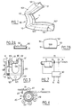
- an inflatable passive safety belt with automatic return and fastening comprises a loop 10, a reel 20 associated with a seat 30 or with a structure 40 on which it is mounted.
- This loop 10 and this reel 20 are intended to be connected by a strap 50; this strap is fixed by mooring devices 60, on the one hand, to the reel and, on the other hand, to one of these seats and structures.
- Pressurizing means 70, for inflating or deflating the strap are under the control of a control unit 80.
- This seat belt is intended to be associated with a seat 30 which comprises, as is conventional, a seat 31, a backrest 32 and if necessary a headrest or headrest 33.
- This seat 30 is usually mounted in a structure 40 such as the shell or the body of a motor vehicle.
- This structure 40 comprises for example a side wall 41 here only shown schematically by the foot or middle post located between the front and rear doors of a motor vehicle.
- This structure also includes a floor 42 on which slides 43 are fixed, the cooperating complementary elements of which are partly mounted thereon and partly under the seat; in this way it is possible to adjust the longitudinal position of the seat in the vehicle as it is conventional.
- the retractor 20 to which one end of the strap of the belt is fixed, is intended to automatically return the strap so as to permanently maintain the latter under a determined tension even when an occupant is seated on his seat. In this way the strap is kept permanently stretched against the body of the occupant while allowing it to move without constraint.
- a retractor with automatic elastic return is under the dependence of a blocking system with inertial control which prohibits unwinding of the strap in the event of violent deceleration of the vehicle or significant tangential acceleration of the strap.
- a reel 20 comprises a drum 21 subjected to an elastic restoring torque as is known, support rollers 22 arranged at the periphery of this drum and at a distance from the latter, as well as a pressure cylinder 23.
- This cylinder 23 is carried by a lever 24 articulated at one of its ends and mounted so as to be able to tilt.
- This lever 24 is biased by a spring 25 so that the pressing cylinder is normally biased towards the drum 21.
- the strap 50 is wound as clearly illustrated.
- the loop 10 includes a bolt 11 to which we will return in detail later and which results in particular from a special configuration obtained by a particular local structure given to the strap.
- This loop also includes a keeper 12.
- This keeper 12 includes a U-shaped body 120 whose two parallel branches 121 are connected by a bridge 122 pierced with a hole 123 for its anchoring, using a conventional technique and for this not illustrated so to secure the keeper to the seat 30 or to the structure 40.
- This body 120 carries a latch 124 which is pivotally mounted using a pin 125 and which is resiliently returned to the closed position by a spring 126.
- This keeper comprises , also, an opening control button 13.
- This button 13 comprises a rod 130 or the like bent approximately in the shape of a C as illustrated to which is fixed a thumb nut 131.
- This rod 130 carries a stopper 132 intended to cooperate with the latch 124 and is subjected to the action of a spring 133.
- This control button 13 is slidably mounted in any suitable conventional manner on the body 120 of the keeper.
- This loop 10 is normally biased in the illustrated closed position where the stop 132 of the control button retains the latch 124 to prevent it from tilting in the direction opposite to the bridge 122.
- the bolt 11 When the bolt 11 is introduced between the two branches 121 from the U and between the deck 122 and the latch 124 so it cannot escape. To release the bolt 11 from the keeper 12 and thus to open the loop 10, it suffices to press on the thumb nut 131 to move the stopper 132 back, which then separates from the latch 124 and frees him.
- the latch 124 can then switch in the direction opposite to that of the hands of a watch (Fig. 3) under the tension of the strap or a traction exerted on it, in the direction opposite to the bridge 122: the bolt 11 is then free to leave the keeper 12 to detach the belt.
- a strap 50 for a seat belt comprises an inextensible and flexible tape 51 having very good mechanical resistance. It is this ribbon which, in the event of a collision, indirectly supports and transmits the forces communicated by the occupant who tends to leave his seat, to the structure.
- One of the ends of the strap, for example of this tape 51 is fixed to the reel 20 more especially to its drum 21, and the other of its ends is fixed to one of these seats 30 or structure 40 ; these fasteners are made using mooring devices 60.
- this tape 51 and more particularly with the part thereof which is furthest from the reel 20, is associated a flexible and waterproof tubular casing 52 preferably a gaseous fluid, for example air.
- This tubular envelope 52 for example resiliently deployable, is in the deflated state as illustrated in the cross section of FIG. 2A, and in the inflated state, this envelope is presented as illustrated in FIG. 2B.
- the end of this envelope 52 which is directed towards the reel 20 is closed at the end of the bag and its opposite end is provided with a nozzle to which we will return later.
- the envelope 52 has a front wall 521 and a rear wall 522 which is intended to face the body of the occupant, that is to say also to seat 30.
- These front and rear walls have different lengths, in the longitudinal direction or in the "chain" direction of the strap: the length of the rear wall 522 is shorter than the length of the front wall 521 for the reasons which will appear later.
- this envelope 52 has an approximately rectangular cross section in the inflated position. This cross section is preferably decreasing from the end comprising the end piece towards the opposite end where the reel is located.
- the part of the strap 50 which comprises both the ribbon 51 and the envelope 52 is divided into a thoracic strand 501 and an abdominal strand 502 by the bolt 11 of the loop.
- the bolt 11 is formed directly on the strap 50. As can be seen in FIG. 1, when the envelope of the strap is inflated, this bolt presents itself approximately with an omega configuration. This special configuration is obtained by a particular local structure of the strap which results from seams 110, as illustrated. The way in which a precise given shape is given in particular to a textile product is well known in sewing and it is not necessary to extend it further.
- the securing devices 60 which are used to fix one of the ends of the strap 50 to the reel 20 and the other of the ends of the latter to one of these seats 30 or structure 40 are conventional. They include for example relatively rigid rods, one end of which is anchored to the seat or to the structure and the other of which is provided, for example, with a rivet or the like engaged in a hole in the body 120 of the keeper 12 of the loop 10 such as the hole 123; the end 60 of the strap is provided with a conventional belt clip fixed for example by a force seam, that is to say a stitch in "Greek" or in slots. We will therefore not expand further on these mooring devices.
- the pressurizing means 70 for inflating or deflating the envelope 52 of the strap 50 of the seat belt according to the invention comprise, inter alia, an electrocompressor 71, an intake valve 72, a relief valve 73 and a pipe 74.
- This pipe 74 is intended to be connected to the end piece 523 of the casing 52 located at the end of the latter which is opposite to that directed towards the reel. This is shown diagrammatically in Fig. 7.
- the control unit 80 comprises piezo-sensitive sensors 81 which are housed one in the seat 31 of the seat 30 and the other either in the backrest 32 or in the headrest 33 thereof.
- These sensors 81 of any suitable suitable type are intended to detect the presence of an occupant on the seat. They are therefore calibrated so as to react to the minimum weight and effort of a person who can take a seat on the seat, for example taking into account the specific regulations applicable with regard to the minimum age of the occupants of the front seats.
- These sensors 81 for the reasons which will be understood hereinafter, are associated so as to constitute a door executing the logic function AND to trigger the operation of the compressor 71.
- This control unit 80 also includes a loop detector 82 which is intended to control the locking of the loop 10 in the presence of the bolt 11 engaged in the keeper 12 when an occupant is actually on the seat 30.
- This detector 82 triggers the shutdown of the electric compressor 71, the closing of the intake valve 72, the opening of the relief valve 73 to cause deflation of the envelope 52 of the strap 50. This will allow the reel 20 to recall the strap 50 as will appear later.
- the strap 50 comprises the mechanically resistant tape 51 and the sealed tubular casing 52.
- This ribbon 51 is made, for example of a conventional seat belt, for example of woven polyester fibers.
- the sealed envelope 52 is made, for example, of inextensible fibers woven as known so as to be extensible and, possibly elastic, as is common. Sealing is obtained directly by the choice of fibers and their weaving mode or else obtained by coating or impregnation with an appropriate substance, for example rubbery or suitable resin.
- This type of waterproof tubular casing is conventional and well known, for example for making the framework or frame of inflatable camping tents.
- This envelope 52 is associated with the ribbon 51 by gluing or sewing or else this envelope is made directly with the ribbon so that the two are directly in one piece.
- the part of the strap 50 which includes both the mechanically resistant tape and the watertight tubular envelope is of a size such that it is capable of enveloping the occupant with the largest diverence provided while being at a distance from the chest and the abdomen thereof, in the locked position of the buckle and in the inflated state of the envelope as we will understand it later.
- the part of the strap with ribbon and envelope is flexible so as to be able to easily change direction by bending or bending on a conventional strap return or even winding on the drum of the reel.
- the bolt 11 between abdominal strand 502 and thoracic strand 501 is able to take the form of an omega in the inflated state of the envelope and to take a relatively rectilinear shape in the deflated state of the envelope.
- This bolt does not constitute a solution of continuity or interruption of the envelope 52, a fluid which is there can pass from one to the other of the two strands.
- the strap is reinforced so that it is not damaged by its repeated contact with the keeper; such contact is likely to affect the conservation of the mechanical strength of the tape and / or the tightness of the envelope.
- the front front walls 521 and rear 522 of the envelope 52 have different lengths, along the longitudinal axis of the strap, different, the length of the rear wall 522 being shorter than that of the wall anterior 521; this applies as well to the thoracic strand 501 as to the abdominal strand 502.
- this difference is suitably chosen, when the envelope is inflated the strands bend and take a concavity which is then directed towards the seat.
- the strap can automatically move itself in the direction of the strike, the bolt oriented towards it, while enveloping the torso of the occupant sitting on the seat and pointing the bolt exactly towards the keeper.
- the cross section, by a transverse plane, of the strap is such that, in the inflated state, the master-couple of the envelope will decrease from the neighboring end of the end piece so as to facilitate the inflation and deflation of the envelope.
- the loop 10 is made of all suitable materials, including metals and plastics; these are chosen so that the buckle meets the standards imposed both with regard to the resistance in the locked position and with regard to the ability to unlock when the strap is under tension, for example due to the weight of the occupant who would be suspended by the strap in the case of a vehicle having poured. There is therefore no need to stretch further.
- the compressor used is, for example, driven by an electric motor powered by the electrical installation on board a vehicle.
- This compressor is able to develop, for example, a pressure slightly higher than atmospheric pressure, the order of magnitude of which is comparable to that necessary for example to inflate an air mattress.
- the amount of air under pressure is for example between two and five liters.
- Inflation can also be carried out using a compressed air tank fitted with a pressure reducer (5 to 6 liters, pressure from 2 to 4 bars or hPa).
- a pressure reducer 5 to 6 liters, pressure from 2 to 4 bars or hPa.
- the inlet valve, the relief valve, the pipe and nozzle are of any conventional type commercially available.
- the control unit 80 which comprises the piezo-sensitive sensors 81 and the loopback detector 82 is, for example, constituted by a suitably programmed microcomputer. These sensors and detector are of any conventional common type which are easily found on the market. The programming of a microcomputer is well known to specialists within the scope of the invention.
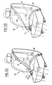
- a safety belt according to the invention has been designed which, with the exception of the pressurizing means 70 and the control unit 80, is incorporated into the seat of a vehicle so as to make body with the latter; in this way the seat can be placed in the passenger compartment of the vehicle with its seat belt with which it is pre-equipped, only electrical and / or fluid connections and connections remain to be made.
- Fig.5A is shown the seat belt according to the invention in the initial position. As can be seen, the strap envelope is in the deflated state and the strap is completely recalled and tensioned by the reel.
- the electrical contact being previously established for example with the unlocking key of the doors or with the ignition key, when an occupant takes place on the seat the piezo-sensitive sensors 81, which are housed one in the seat and the other either in the backrest or in the headrest, detec try his presence.
- the control unit 80 then triggers the opening of the inlet valve 72, the closing of the load-shedding valve 73 and the starting of the electrocompressor 71; the compressor then supplies pressurized fluid, for example air, to the casing by means of the pipe 74 connected to the nozzle 523.
- pressurized fluid for example air
- the blowing of pressurized fluid takes place through the end of the envelope which is opposite to that directed towards the reel and the section of the envelope going decreasing in the same direction, it is therefore seen that first of all what is apparent from the strap, essentially its abdominal strand, swells under pressure which develops in the envelope, then the strap unwinds gradually against the stress of the reel while continuing to inflate; the strap begins to take the configuration illustrated in Fig.5B.
- the bolt is engaged in the keeper and is locked there.
- the loop detector detects this situation, it sends a signal to the control unit so as to close the inlet valve stop the electrocharger and open the load-shedding valve.
- the envelope deflates and therefore exerts no more stress on the strap and the latter is then no longer subjected to the tension exerted by the reel.
- the latter can then act on the strap to tighten it by partially rewinding it, in just enough quantity so that the thoracic and abdominal strands are applied against the body of the occupant.
- the inflation is facilitated by the fact of the change of direction ensured by a return, the strap which exits from the top of the seat back and that the inflation of the envelope of the thoracic strand is only done. as it appears.
- the structure of the bolt is such that it does not interrupt the continuity of the sealed envelope so that the air blown in by the nozzle can propagate to the thoracic strand.
- the return effort of the retractor can be neutralized or lessened. This can be achieved by involving the control unit.
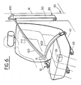
- Fig.6 there is illustrated an alternative embodiment of the embodiment of the seat belt according to the invention.
- the strap and its retractor are not incorporated into the seat but associated with the structure of the vehicle as is conventional.
- a strap return 410 fixed for example to the middle or upright leg located between the front and rear doors of a four-door vehicle, as is conventional.
- a pressure cylinder is used as illustrated in FIG. 4 schematically.
Landscapes
- Engineering & Computer Science (AREA)
- Mechanical Engineering (AREA)
- Air Bags (AREA)
- Automotive Seat Belt Assembly (AREA)
Applications Claiming Priority (2)
| Application Number | Priority Date | Filing Date | Title |
|---|---|---|---|
| FR8814051A FR2638411B1 (fr) | 1988-10-27 | 1988-10-27 | Ceinture de securite passive gonflable a bouclage automatique |
| FR8814051 | 1988-10-27 |
Publications (2)
| Publication Number | Publication Date |
|---|---|
| EP0366518A1 true EP0366518A1 (de) | 1990-05-02 |
| EP0366518B1 EP0366518B1 (de) | 1992-03-25 |
Family
ID=9371336
Family Applications (1)
| Application Number | Title | Priority Date | Filing Date |
|---|---|---|---|
| EP19890402796 Expired - Lifetime EP0366518B1 (de) | 1988-10-27 | 1989-10-10 | Aufblasbarer passiver Sicherheitsgurt mit selbsttätigem Anschnallen |
Country Status (4)
| Country | Link |
|---|---|
| EP (1) | EP0366518B1 (de) |
| DE (1) | DE68901076D1 (de) |
| ES (1) | ES2030288T3 (de) |
| FR (1) | FR2638411B1 (de) |
Cited By (5)
| Publication number | Priority date | Publication date | Assignee | Title |
|---|---|---|---|---|
| WO1999039940A1 (de) | 1998-02-04 | 1999-08-12 | Breed Automotive Technology, Inc. | Dreipunkt-sicherheitsgurt |
| WO1999040247A1 (de) * | 1998-02-04 | 1999-08-12 | Johann Berger | Aufblasbares gurtband |
| WO2008054187A1 (fr) * | 2006-10-30 | 2008-05-08 | Mhadi Abdellah | Ceinture de securite pour vehicules a action automatique |
| DE102014204186A1 (de) | 2014-03-07 | 2015-09-10 | Autoliv Development Ab | Sicherheitsgurteinrichtung für ein Kraftfahrzeug |
| CN108784137A (zh) * | 2018-07-27 | 2018-11-13 | 浙江凯儿宝安全科技有限公司 | 轻量化婴儿安全提篮 |
Families Citing this family (1)
| Publication number | Priority date | Publication date | Assignee | Title |
|---|---|---|---|---|
| DE102011111932A1 (de) * | 2011-08-30 | 2013-02-28 | GM Global Technology Operations LLC (n. d. Ges. d. Staates Delaware) | Sicherheitsgurtanordnung für einen Fahrzeugsitz eines Fahrzeuges und Fahrzeug mit der Sicherheitsgurtanordnung |
Citations (6)
| Publication number | Priority date | Publication date | Assignee | Title |
|---|---|---|---|---|
| US3190694A (en) * | 1963-04-22 | 1965-06-22 | Isaac Peter | Safety belt systems for vehicles |
| FR2197320A5 (de) * | 1972-08-23 | 1974-03-22 | Takata Kotyo Co Ltd | |
| FR2213783A1 (de) * | 1973-01-12 | 1974-08-09 | Takata Kojyo Co | |
| FR2225012A5 (en) * | 1973-04-06 | 1974-10-31 | Hautemont Jean Claude | Automatically unrolling vehicle seat belt - has tube along belt supplied with air from bag in seat compressed by passenger |
| US4160565A (en) * | 1976-08-31 | 1979-07-10 | Honda Giken Kogyo Kabushiki Kaisha | Seat belt device |
| DE3702976A1 (de) * | 1987-02-02 | 1988-08-11 | Linde & Wiemann Gmbh Kg | Sicherheitsgurt in kraftfahrzeugen |
Family Cites Families (1)
| Publication number | Priority date | Publication date | Assignee | Title |
|---|---|---|---|---|
| DE3232946A1 (de) * | 1982-09-04 | 1984-03-08 | Wolfgang 5000 Köln Schmalz | Sicherheitsgurt, insbesondere mit automatischer aufrollvorrichtung, mit einem den auflagedruck mindernden polsterteil |
-
1988
- 1988-10-27 FR FR8814051A patent/FR2638411B1/fr not_active Expired - Fee Related
-
1989
- 1989-10-10 EP EP19890402796 patent/EP0366518B1/de not_active Expired - Lifetime
- 1989-10-10 ES ES89402796T patent/ES2030288T3/es not_active Expired - Lifetime
- 1989-10-10 DE DE8989402796T patent/DE68901076D1/de not_active Expired - Fee Related
Patent Citations (6)
| Publication number | Priority date | Publication date | Assignee | Title |
|---|---|---|---|---|
| US3190694A (en) * | 1963-04-22 | 1965-06-22 | Isaac Peter | Safety belt systems for vehicles |
| FR2197320A5 (de) * | 1972-08-23 | 1974-03-22 | Takata Kotyo Co Ltd | |
| FR2213783A1 (de) * | 1973-01-12 | 1974-08-09 | Takata Kojyo Co | |
| FR2225012A5 (en) * | 1973-04-06 | 1974-10-31 | Hautemont Jean Claude | Automatically unrolling vehicle seat belt - has tube along belt supplied with air from bag in seat compressed by passenger |
| US4160565A (en) * | 1976-08-31 | 1979-07-10 | Honda Giken Kogyo Kabushiki Kaisha | Seat belt device |
| DE3702976A1 (de) * | 1987-02-02 | 1988-08-11 | Linde & Wiemann Gmbh Kg | Sicherheitsgurt in kraftfahrzeugen |
Cited By (9)
| Publication number | Priority date | Publication date | Assignee | Title |
|---|---|---|---|---|
| WO1999039940A1 (de) | 1998-02-04 | 1999-08-12 | Breed Automotive Technology, Inc. | Dreipunkt-sicherheitsgurt |
| WO1999040247A1 (de) * | 1998-02-04 | 1999-08-12 | Johann Berger | Aufblasbares gurtband |
| DE19804365A1 (de) * | 1998-02-04 | 1999-08-12 | Hs Tech & Design | Dreipunkt-Sicherheitsgurt |
| DE19804365C2 (de) * | 1998-02-04 | 2000-06-08 | Hs Tech & Design | Dreipunkt-Sicherheitsgurt |
| US6340173B1 (en) * | 1998-02-04 | 2002-01-22 | Breed Automotive Technology, Inc. | Three-point seat belt |
| WO2008054187A1 (fr) * | 2006-10-30 | 2008-05-08 | Mhadi Abdellah | Ceinture de securite pour vehicules a action automatique |
| DE102014204186A1 (de) | 2014-03-07 | 2015-09-10 | Autoliv Development Ab | Sicherheitsgurteinrichtung für ein Kraftfahrzeug |
| DE102014204186B4 (de) | 2014-03-07 | 2024-10-17 | Autoliv Development Ab | Sicherheitsgurteinrichtung für ein Kraftfahrzeug |
| CN108784137A (zh) * | 2018-07-27 | 2018-11-13 | 浙江凯儿宝安全科技有限公司 | 轻量化婴儿安全提篮 |
Also Published As
| Publication number | Publication date |
|---|---|
| FR2638411B1 (fr) | 1994-05-06 |
| DE68901076D1 (de) | 1992-04-30 |
| EP0366518B1 (de) | 1992-03-25 |
| FR2638411A1 (fr) | 1990-05-04 |
| ES2030288T3 (es) | 1992-10-16 |
Similar Documents
| Publication | Publication Date | Title |
|---|---|---|
| AU596962B2 (en) | Automatic seat belt adjusting system | |
| US7021655B2 (en) | Passenger protecting apparatus | |
| US5492368A (en) | Rollover seat system | |
| US20040075252A1 (en) | Inflatable head restraint | |
| FR2684057A1 (fr) | Dispositif pour proteger la tete d'un occupant de vehicule automobile. | |
| US3929205A (en) | Three point safety belt system with inertia actuated inflatable belts | |
| JPH0648267A (ja) | シートベルト装置 | |
| JP2004537449A (ja) | 膨張統合慣性リールを用いた膨張式シートベルト拘束システム | |
| US20020043836A1 (en) | Tether strap that allows rotation of a safety seat about a vertical axis | |
| EP0366518B1 (de) | Aufblasbarer passiver Sicherheitsgurt mit selbsttätigem Anschnallen | |
| FR2814414A1 (fr) | Siege de vehicule automobile comportant un appui-tete et un sac gonflable a l'interieur de l'appui-tete | |
| US3869145A (en) | Self-applying vehicle safety belt | |
| FR2848157A1 (fr) | Agencement d'un siege d'enfant susceptible de basculer vers une position de protection dans une automobile | |
| EP4392295A1 (de) | Fahrzeugsitz mit eingebautem sicherheitssystem | |
| JP2002513353A (ja) | 自動車の小柄な搭乗者用シートのシートベルト及びベルトアダプタ | |
| EP0449700A1 (de) | Selbstsperrender Sicherheitsgurtumlenkbeschlag | |
| FR2465615A1 (en) | Safety belt for vehicle seat - includes part which is inflated by passenger weight acting on fluid pocket displacing fluid | |
| US7566072B2 (en) | Occupant restraining apparatus | |
| JP2001225723A (ja) | シートベルト装置用プリテンショナー | |
| ES2271500T3 (es) | Dispositivo plegable de sujeccion de la correa de un cinturon de seguridad. | |
| FR2806679A1 (fr) | Siege de vehicule automobile comportant un sac gonflable de securite dans une partie laterale de son dossier | |
| FR3102733A1 (fr) | ceinture de sécurité dotée d’un mécanisme de déploiement d’un airbag | |
| EP3815988B1 (de) | Fahrzeugsitz, der mit einer thorax-schutzvorrichtung ausgestattet ist | |
| EP1110823B1 (de) | Sicherheitsgurtvorrichtung mit einem abnehmbaren Gassack | |
| JPS5837410Y2 (ja) | ベルトのスリツプ防止装置 |
Legal Events
| Date | Code | Title | Description |
|---|---|---|---|
| PUAI | Public reference made under article 153(3) epc to a published international application that has entered the european phase |
Free format text: ORIGINAL CODE: 0009012 |
|
| AK | Designated contracting states |
Kind code of ref document: A1 Designated state(s): BE DE ES GB IT NL SE |
|
| 17P | Request for examination filed |
Effective date: 19900405 |
|
| 17Q | First examination report despatched |
Effective date: 19910711 |
|
| GRAA | (expected) grant |
Free format text: ORIGINAL CODE: 0009210 |
|
| RAP1 | Party data changed (applicant data changed or rights of an application transferred) |
Owner name: CESA COMPAGNIE EUROPEENNE DE SIEGES POUR AUTOMOBIL |
|
| AK | Designated contracting states |
Kind code of ref document: B1 Designated state(s): BE DE ES GB IT NL SE |
|
| ITF | It: translation for a ep patent filed | ||
| REF | Corresponds to: |
Ref document number: 68901076 Country of ref document: DE Date of ref document: 19920430 |
|
| GBT | Gb: translation of ep patent filed (gb section 77(6)(a)/1977) | ||
| REG | Reference to a national code |
Ref country code: ES Ref legal event code: FG2A Ref document number: 2030288 Country of ref document: ES Kind code of ref document: T3 |
|
| PLBE | No opposition filed within time limit |
Free format text: ORIGINAL CODE: 0009261 |
|
| STAA | Information on the status of an ep patent application or granted ep patent |
Free format text: STATUS: NO OPPOSITION FILED WITHIN TIME LIMIT |
|
| 26N | No opposition filed | ||
| EAL | Se: european patent in force in sweden |
Ref document number: 89402796.0 |
|
| PGFP | Annual fee paid to national office [announced via postgrant information from national office to epo] |
Ref country code: NL Payment date: 19980923 Year of fee payment: 10 |
|
| PGFP | Annual fee paid to national office [announced via postgrant information from national office to epo] |
Ref country code: ES Payment date: 19981001 Year of fee payment: 10 |
|
| PGFP | Annual fee paid to national office [announced via postgrant information from national office to epo] |
Ref country code: SE Payment date: 19981021 Year of fee payment: 10 |
|
| PGFP | Annual fee paid to national office [announced via postgrant information from national office to epo] |
Ref country code: BE Payment date: 19981117 Year of fee payment: 10 |
|
| PGFP | Annual fee paid to national office [announced via postgrant information from national office to epo] |
Ref country code: GB Payment date: 19990929 Year of fee payment: 11 |
|
| PG25 | Lapsed in a contracting state [announced via postgrant information from national office to epo] |
Ref country code: ES Free format text: LAPSE BECAUSE OF NON-PAYMENT OF DUE FEES Effective date: 19991011 |
|
| PG25 | Lapsed in a contracting state [announced via postgrant information from national office to epo] |
Ref country code: SE Free format text: THE PATENT HAS BEEN ANNULLED BY A DECISION OF A NATIONAL AUTHORITY Effective date: 19991030 |
|
| PG25 | Lapsed in a contracting state [announced via postgrant information from national office to epo] |
Ref country code: BE Free format text: LAPSE BECAUSE OF NON-PAYMENT OF DUE FEES Effective date: 19991031 |
|
| BERE | Be: lapsed |
Owner name: CIE EUROPEENNE DE SIEGES POUR AUTOMOBILES CESA Effective date: 19991031 |
|
| PG25 | Lapsed in a contracting state [announced via postgrant information from national office to epo] |
Ref country code: NL Free format text: LAPSE BECAUSE OF NON-PAYMENT OF DUE FEES Effective date: 20000501 |
|
| EUG | Se: european patent has lapsed |
Ref document number: 89402796.0 |
|
| NLV4 | Nl: lapsed or anulled due to non-payment of the annual fee |
Effective date: 20000501 |
|
| PGFP | Annual fee paid to national office [announced via postgrant information from national office to epo] |
Ref country code: DE Payment date: 20001009 Year of fee payment: 12 |
|
| PG25 | Lapsed in a contracting state [announced via postgrant information from national office to epo] |
Ref country code: GB Free format text: LAPSE BECAUSE OF NON-PAYMENT OF DUE FEES Effective date: 20001010 |
|
| GBPC | Gb: european patent ceased through non-payment of renewal fee |
Effective date: 20001010 |
|
| PG25 | Lapsed in a contracting state [announced via postgrant information from national office to epo] |
Ref country code: DE Free format text: LAPSE BECAUSE OF NON-PAYMENT OF DUE FEES Effective date: 20020702 |
|
| REG | Reference to a national code |
Ref country code: ES Ref legal event code: FD2A Effective date: 20001113 |
|
| PG25 | Lapsed in a contracting state [announced via postgrant information from national office to epo] |
Ref country code: IT Free format text: LAPSE BECAUSE OF NON-PAYMENT OF DUE FEES;WARNING: LAPSES OF ITALIAN PATENTS WITH EFFECTIVE DATE BEFORE 2007 MAY HAVE OCCURRED AT ANY TIME BEFORE 2007. THE CORRECT EFFECTIVE DATE MAY BE DIFFERENT FROM THE ONE RECORDED. Effective date: 20051010 |