EP0366562A1 - Zerlegbare Haltevorrichtung eines piezoelektrischen Resonators in einem Gehäuse - Google Patents
Zerlegbare Haltevorrichtung eines piezoelektrischen Resonators in einem Gehäuse Download PDFInfo
- Publication number
- EP0366562A1 EP0366562A1 EP89402975A EP89402975A EP0366562A1 EP 0366562 A1 EP0366562 A1 EP 0366562A1 EP 89402975 A EP89402975 A EP 89402975A EP 89402975 A EP89402975 A EP 89402975A EP 0366562 A1 EP0366562 A1 EP 0366562A1
- Authority
- EP
- European Patent Office
- Prior art keywords
- resonator
- springs
- housing
- clamps
- clamp
- Prior art date
- Legal status (The legal status is an assumption and is not a legal conclusion. Google has not performed a legal analysis and makes no representation as to the accuracy of the status listed.)
- Granted
Links
- 229910045601 alloy Inorganic materials 0.000 claims abstract description 5
- 239000000956 alloy Substances 0.000 claims abstract description 5
- 239000002184 metal Substances 0.000 claims abstract description 5
- 239000000463 material Substances 0.000 claims description 11
- 229910001092 metal group alloy Inorganic materials 0.000 claims 1
- 230000001747 exhibiting effect Effects 0.000 abstract 1
- 239000013078 crystal Substances 0.000 description 16
- 239000000725 suspension Substances 0.000 description 9
- 230000001464 adherent effect Effects 0.000 description 8
- 238000004519 manufacturing process Methods 0.000 description 6
- 239000010453 quartz Substances 0.000 description 6
- VYPSYNLAJGMNEJ-UHFFFAOYSA-N silicon dioxide Inorganic materials O=[Si]=O VYPSYNLAJGMNEJ-UHFFFAOYSA-N 0.000 description 6
- 238000005452 bending Methods 0.000 description 4
- 230000002093 peripheral effect Effects 0.000 description 4
- 230000035939 shock Effects 0.000 description 4
- 230000001681 protective effect Effects 0.000 description 3
- 230000035882 stress Effects 0.000 description 3
- 230000001133 acceleration Effects 0.000 description 2
- 238000003466 welding Methods 0.000 description 2
- 229910000831 Steel Inorganic materials 0.000 description 1
- 230000032683 aging Effects 0.000 description 1
- 230000006835 compression Effects 0.000 description 1
- 238000007906 compression Methods 0.000 description 1
- 230000007547 defect Effects 0.000 description 1
- 230000000694 effects Effects 0.000 description 1
- 230000005284 excitation Effects 0.000 description 1
- 230000005484 gravity Effects 0.000 description 1
- 230000003100 immobilizing effect Effects 0.000 description 1
- 239000011810 insulating material Substances 0.000 description 1
- 239000010959 steel Substances 0.000 description 1
Images

Classifications
-
- H—ELECTRICITY
- H03—ELECTRONIC CIRCUITRY
- H03H—IMPEDANCE NETWORKS, e.g. RESONANT CIRCUITS; RESONATORS
- H03H9/00—Networks comprising electromechanical or electro-acoustic elements; Electromechanical resonators
- H03H9/02—Details
- H03H9/05—Holders or supports
- H03H9/0504—Holders or supports for bulk acoustic wave devices
- H03H9/0528—Holders or supports for bulk acoustic wave devices consisting of clips
-
- H—ELECTRICITY
- H03—ELECTRONIC CIRCUITRY
- H03H—IMPEDANCE NETWORKS, e.g. RESONANT CIRCUITS; RESONATORS
- H03H9/00—Networks comprising electromechanical or electro-acoustic elements; Electromechanical resonators
- H03H9/02—Details
- H03H9/05—Holders or supports
- H03H9/09—Elastic or damping supports
Definitions
- the present invention which is due to the work of Messrs R. Besson, R. Delaite, G. Renard, JP Valentin and JL Vaterkowski of the Chronometry, Electronics and Piezoelectricity Laboratory of the National School of Mechanics and Microtechnics of University of Franche-Comté - Besancon, concerns the mechanical structures for supporting piezoelectric resonators and more particularly a removable device for supporting a piezoelectric resonator inside a housing, comprising four identical independent U-shaped clamps which are produced in a material whose coefficient of expansion in the axial direction of the resonator is practically identical to that of the material constituting the resonator and which each cooperate with a pair of springs each consisting of a round metal wire made of an alloy with high elastic limit, the whole clamps and springs having symmetry with respect to two planes s axial of the resonator perpendicular to each other, as well as with respect to a median radial plane of the resonator.
- a resonator crystal is constituted by a plano-convex or bi-convex quartz plate with circular outline, on the front faces of which are directly deposited metal electrodes, called adherent electrodes.
- the quartz plate with adherent electrodes is externally limited by a quartz crown serving to support the crystal-resonator.
- the crystal-resonator is connected to a quartz crown by bridges cut in the mass.
- the electrodes can be adherent or non-adherent. In the latter case, the electrodes are deposited on quartz plates of the same cut as the crystal and of similar shape and only the crowns of the electro-support plates. are in contact with the crown of the vibrating crystal.
- resonator Whatever type of resonator is used, it is generally necessary to incorporate this resonator in a protective case which, if it is waterproof, also makes it possible to create a space in which there is a more or less high vacuum which improves the operating conditions of the resonator and therefore the quality of the latter.
- the housing and the crystal-resonator however have different mechanical and thermal characteristics, so it is necessary to produce a specific mechanical structure making it possible to limit the influence of external disturbances by bringing the minimum of stresses to the center of the crystal.
- first and second identical half-shells for positioning the resonator which are made of a material of the same nature and of the same section as that making up the resonator, each have the shape of a cross-piece and each have four branches the free ends of which define angles having a horizontal surface of small surface area slightly raised with respect to the central part of the corresponding half-shell and a vertical branch for retaining the edge of the resonator; and four identical independent clamps for immobilizing the two half-shells which have the shape of a lying U and each have at the ends of each branch of the U two stop elements bearing on two superposed branches of the two half-shells, on the faces of the branches opposite to said horizontal spans cooperate with four pairs of suspension springs connecting the four flanges immobilization to the housing.
- the suspension springs of the retaining flanges of the cross-shaped half-shells are connected directly to the housing and immobilized by one of their ends at the junction between different walls constituting the housing. This prevents obtaining a complete decoupling between the housing, the main role of which is to maintain the vacuum in the space internal to the housing, and which can be subjected to shocks or deformations, and the actual suspension which must remain the most symmetrical possible. Furthermore, the production of half-shells in the shape of a cross in a material of the same nature and of the same cut as that making up the resonator constitutes a constraint in terms of manufacturing cost.
- the present invention aims precisely to remedy the aforementioned drawbacks and to allow the production of a resonator support device in a housing which is simpler and less costly to manufacture than existing devices, and which moreover ensures more effective decoupling between the housing and the suspension members of the resonator, while also allowing easy disassembly and reassembly of the suspension members.
- a support device of the type defined at the head of the description characterized in that it further comprises a removable cylindrical part placed inside the housing in the vicinity of the side wall of the housing, extending over the entire height of the internal space defined between the upper and lower walls of the housing and having on its internal face a circular groove situated in a median plane parallel to the upper and lower walls of the housing, in that for each pair of springs cooperating with the same clamp, one of the springs is engaged by a first portion in an upper groove formed in the flat rear face of said clamp at the upper part thereof, and by a second portion in said circular groove while the other spring is engaged by a first portion in a lower groove formed in the flat rear face of said clamp at the lower part thereof, and by a second portion in said circular groove, and said second portions of the springs engaged in said circular groove are secured to each other and project backwards relative to the rear face of said clamp, and in that the internal faces of the clamps substantially perpendicular to the rear face of said clamps rest directly on the pe
- the circular groove has an annular shape with rectangular section.
- the cylindrical part is metallic and has a shoulder at one of its ends to provide a free space between the side wall of the housing and the cylindrical part over most of the height thereof.
- the internal faces of the clamps substantially perpendicular to the rear face have a regular surface in contact with the upper and lower external faces of the resonator or of the support discs of the electrodes of the resonator over an area extending radially over a distance on the order of 1 to 2 mm.
- recesses are formed in the walls of the support discs for the electrodes of the resonator in areas extending radially towards the center of the resonator the areas at which the clamps are in contact with the upper external faces and support discs over a distance of about 1 to 2 mm.
- the springs have an interruption at their first portion engaged in a groove on the rear face of the clamp with which they cooperate, are symmetrical with respect to a vertical radial plane situated at the level of said interruption and have a configuration such that each half-spring divided by said vertical radial plane of symmetry comprises a first part horizontal rectilinear intended to be embedded in a groove of the receiving clamp, a curved vertical part disposed outside of the receiving clamp in a plane forming an angle of 45 ° relative to the plane of symmetry of the spring, and a second horizontal part which is connected to the end of the curved vertical part remote from the first horizontal part and constitutes a part of said second portion situated behind the first rectilinear horizontal part which itself constitutes a part of said first portion .
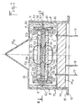
- FIGS. 1 and 2 show all of the removable means for supporting a resonator 1 inside a protective box 10.
- FIG. 1 a housing arranged according to FIG. 1 and the terms "lower, upper, vertical, horizontal," used in the present description, are to be interpreted in conjunction with the description of this figure 1 and aim to allow a description of the various elements in their relative positions from the position of Figure 1.
- the housing 10 can naturally be placed in all kinds of other positions and said terms "lower, upper, vertical, horizontal” should therefore not be considered as limiting with regard to the position of the housing 10.
- the resonator 1 may be constituted by a crystal-resonator with adherent electrodes, that is to say by a plate of a piezoelectric material of cut given on the main faces of which are arranged metal electrodes.
- the resonator 1 may however also be constituted by a more complex assembly, such as that shown in elevation in FIG. 1, with a resonator crystal 101 constituted, as in the previous case, by a plate of a piezoelectric material for example of the type bi-plane, but without electrodes and having an external support ring 110 delimited by lights 111 and connected to the active central part of the crystal by bridges and two plates 102, 103 also each having a peripheral support part which carries on the outer ring 110 of the crystal itself, so as to form at this ring a stack of surfaces adjusted to one another.
- a resonator crystal 101 constituted, as in the previous case, by a plate of a piezoelectric material for example of the type bi-plane, but without electrodes and having an external support ring 110 delimited by lights 111 and connected to the active central part of the crystal by bridges and two plates 102, 103 also each having a peripheral support part which carries on the outer ring 110 of the crystal itself, so as to form
- the central parts 121, 131 of the faces of the plates 102, 103, located opposite the crystal 101, and which are not in contact with the latter carry so-called excitation electrodes non-adherent electrodes 122, 132.
- the compact assembly constituted by the crystal 101 and the plates 102, 103 carrying electrodes can then be considered as a block equivalent to a resonator with adherent electrodes, the elements of the resonator support device acting in this case on the peripheral parts of the electrode support plates while in the case of a resonator with adherent electrodes, the support device is in contact with the peripheral part of the crystal-resonator itself.
- references 123 and 133 designate conductive paths connecting the electrodes 122, 132 to pads 124, 134 respectively intended to allow electrical connections to be made with the connection pins 17, 18, 19 by wires not shown in the drawings.
- the whole of the support device according to the invention is designed so as to be entirely symmetrical with respect to two axial planes of the resonator 1 perpendicular to each other, as well as with respect to a median radial plane of the resonator 1 and to achieve complete decoupling between the protective housing and the resonator so that actions due to external disturbances (accelerations, shocks, vibrations, pressure) cannot transmit torsion or bending moments to the center of the crystal.
- the support means are further designed to include a limited number of parts and to be removable.
- a first element constituting the means for supporting the resonator 1 in the housing is constituted by a removable cylindrical part 6, made of steel, which is disposed between the flat wall 12 of the base of the housing, which constitutes the bottom of the cavity formed inside the housing, and the upper wall 13 of the housing cover.
- the cylindrical part 6 is placed in the vicinity of the cylindrical side wall 11 of the housing cover and has on its internal face a circular groove 62 situated in a median plane parallel to the upper 13 and lower 12 walls of the housing 10.
- the groove 62 has a annular shape with rectangular section and is intended to receive by snap-fastening of the adjoining parts of a pair of springs 5 which will be described later.
- the cylindrical part 6 has a shoulder 61 at one of its ends to provide a free space 60 between the side wall 11 of the housing 10 and the cylindrical part 6 over most of the height thereof.
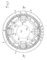
- the means for supporting the whole of the resonator 1 which, as shown in the figures, may consist of a stack of three discs, namely two discs 102, 103 supporting electrodes and a central disc 101 constituting the resonator proper , include four identical independent clamps 4 arranged at 90 ° from each other, and cooperating directly with the upper external 126 and lower 136 faces of the resonator.
- Each clamp 4 has the shape of a coated U and comprises a flat vertical part 41 in the rear face of which two horizontal grooves 46, 47 are formed in the vicinity of the lateral branches 42, 43 of the clamp 4.
- the clamping forces applied by the four clamps 4 are identical, collinear and exerted perpendicular to the upper outer 126 and lower 136 faces of the resonator 1 so that no bending moment is transmitted to it.
- a material is chosen for the clamps whose coefficient of expansion is in the axial direction, identical to, or very close to that of crystal 1.
- a quartz crystal one can thus choose a material of the type of that known under the name PHYNOX.
- the "suspension" function of the crystal assembly 1 with its disks 102, 103 electrode support and the clamps 4 in the housing 10 is provided by eight identical springs 5 which connect the clamps 4 to the cylindrical part 6.
- the combination of a cylindrical part 6 distinct from the housing 10 and springs 5 effectively isolates the sensitive part of the resonator 1 from the external actions applied to the housing 10.
- the springs 5 also make it possible to compensate for manufacturing defects between the various assembled elements.
- the suspension is designed symmetrically so that the actions due to external disturbances (accelerations, shocks, vibrations, pressure) are not likely to transmit moments of torsion or bending in the center of the crystal.
- Eight springs of shape 5 are thus arranged two by two at 90 ° from each other, each pair of springs acting on the lower and upper parts of a clamp 4.
- the arrangement of springs 5, their particular shape shown in Figures 1 to 3 and the use of round wire of small section, for example with a diameter of 2 tenths of a millimeter, for the production of the springs 5 make it possible to guarantee that the elastic center of the suspension corresponds with the center of gravity of the mass of the system, that the three degrees of freedom are in translation, and that with these are associated three identical stiffness coefficients.
- the assembly may be subjected to shocks; it is the suspension which is capable of "absorbing” them and minimizing their influences.
- the springs 5 being able to work in torsion and in bending, it is advisable to choose to carry out a special alloy with high elastic limit (for example an alloy of the type known under the name PHYNOX).
- the springs 5 which make the connection between the clamps and the cylindrical piece 6, can be simply embedded in the groove 62 of the cylindrical piece 6, so that the assembly consisting of the clamps 4 and the springs 5 can be disassembled relative to the cylindrical part 6, if necessary, and naturally with respect to the resonator 1.
- connection with the springs 5 can be made by welding, the relative positioning being ensured by the two grooves 46, 47 cut on the back of each clamp 4.
- one of the springs is engaged by a first portion 51, 52 in the upper groove 46 formed in the flat rear face 41 of the clamp 4 at the upper part thereof, and by a second portion 57 in the circular groove 62 of the cylindrical part 6 while the other spring is engaged by a first portion 51, 52 in the lower groove 47 formed in the flat rear face 41 of the clamp 4 at the lower part thereof and by a second portion 57 in the circular groove 62.
- the second portions 57 of the springs engaged in the circular groove 62 are joined together for example by laser welding and are projected in rear relative to the rear face 41 of the clamp over a distance of between approximately 1 and 2 mm and preferably of the order of 1.5 mm.
- the springs 5 have an interruption 50 at their first portion 51, 52 engaged in a groove 46 or 47 of the rear face of the clamp with which they cooperate.
- the springs 5 are symmetrical with respect to a plane situated at the level of said interruption 50, which corresponds to the vertical median plane of a clamp 4.
- Each half-spring divided by said vertical radial plane of symmetry comprises a first rectilinear horizontal part 51; 52 intended to be fitted into a groove 46 or 47 of the receiving clamp 4, a curved vertical part 53; 54 corresponding approximately to a fraction of a circle disposed outside of the receiving clamp 4 in a plane forming an angle of 45 ° relative to the plane of symmetry of the spring, and a second horizontal part 57 which is connected to the end 55 ; 56 of the curved vertical part 53; 54 remote from the first horizontal part 51; 52 and constitutes a part of said second portion 57 situated behind the first rectilinear horizontal part 51; 52 which itself constitutes a part of said first portion.
- the internal faces 42, 43 of the clamps 4 substantially perpendicular to the rear face 41 have a surface regular in contact with the upper and lower external faces 126, 136 of the disks 102, 103 for supporting the electrodes of the resonator over an area extending radially over a distance of the order of 1 to 2 mm.
- recesses 125, 135 are formed in the walls of the discs 102, 103 for supporting the electrodes of the resonator 1 in areas extending radially towards the center of the resonator the areas at which the clamps 4 are in contact with the upper and lower external faces 126, 136 of the support discs 102, 103 over a distance of the order of 1 to 2 mm, in order to prevent the clamps 4 which are directly engaged with the peripheral parts of the discs 102, 103 transmit stresses to the central parts of the discs 102, 103 and consequently of the crystal 101 constituting the resonator proper.
Landscapes
- Physics & Mathematics (AREA)
- Acoustics & Sound (AREA)
- Piezo-Electric Or Mechanical Vibrators, Or Delay Or Filter Circuits (AREA)
Priority Applications (1)
| Application Number | Priority Date | Filing Date | Title |
|---|---|---|---|
| AT89402975T ATE102771T1 (de) | 1988-10-28 | 1989-10-27 | Zerlegbare haltevorrichtung eines piezoelektrischen resonators in einem gehaeuse. |
Applications Claiming Priority (2)
| Application Number | Priority Date | Filing Date | Title |
|---|---|---|---|
| FR8814197 | 1988-10-28 | ||
| FR8814197A FR2638587B1 (fr) | 1988-10-28 | 1988-10-28 | Dispositif demontable de support d'un resonateur piezoelectrique a l'interieur d'un boitier |
Publications (2)
| Publication Number | Publication Date |
|---|---|
| EP0366562A1 true EP0366562A1 (de) | 1990-05-02 |
| EP0366562B1 EP0366562B1 (de) | 1994-03-09 |
Family
ID=9371430
Family Applications (1)
| Application Number | Title | Priority Date | Filing Date |
|---|---|---|---|
| EP89402975A Expired - Lifetime EP0366562B1 (de) | 1988-10-28 | 1989-10-27 | Zerlegbare Haltevorrichtung eines piezoelektrischen Resonators in einem Gehäuse |
Country Status (7)
| Country | Link |
|---|---|
| US (1) | US5006750A (de) |
| EP (1) | EP0366562B1 (de) |
| JP (1) | JPH0817301B2 (de) |
| AT (1) | ATE102771T1 (de) |
| CA (1) | CA2000886C (de) |
| DE (1) | DE68913652T2 (de) |
| FR (1) | FR2638587B1 (de) |
Families Citing this family (6)
| Publication number | Priority date | Publication date | Assignee | Title |
|---|---|---|---|---|
| JP3825890B2 (ja) * | 1997-07-28 | 2006-09-27 | キヤノン株式会社 | 振動アクチュエータ |
| CN100517467C (zh) * | 2003-05-12 | 2009-07-22 | 新科实业有限公司 | 用于形成微致动器的方法和系统 |
| US7067964B1 (en) * | 2004-05-14 | 2006-06-27 | The United States Of America As Represented By The Secretary Of The Army | Piezoelectric resonator with reduced deformation sensitivity |
| DE602005027217D1 (de) * | 2004-07-13 | 2011-05-12 | Draper Lab Charles S | Vorrichtung zum aussetzen einer vorrichtung in chipgrösse und einem atomuhrensystem |
| US9083263B2 (en) * | 2012-12-13 | 2015-07-14 | Schlumberger Technology Corporation | Apparatus to provide a time reference |
| CN106785279B (zh) * | 2017-02-21 | 2019-04-19 | 安徽中瑞通信科技股份有限公司 | 一种多系统合路平台安装结构 |
Citations (1)
| Publication number | Priority date | Publication date | Assignee | Title |
|---|---|---|---|---|
| FR2583584A1 (fr) * | 1985-06-14 | 1986-12-19 | Ecole Nale Sup Meca Microtechn | Dispositif de support d'un resonateur piezoelectrique a l'interieur d'un boitier |
Family Cites Families (4)
| Publication number | Priority date | Publication date | Assignee | Title |
|---|---|---|---|---|
| US2315392A (en) * | 1941-07-05 | 1943-03-30 | Rca Corp | Art of mounting piezoelectric crystals |
| FR2445029A1 (fr) * | 1978-12-19 | 1980-07-18 | France Etat | Resonateur piezoelectrique a tiroir |
| FR2562352B1 (fr) * | 1984-03-30 | 1989-10-20 | Cepe | Resonateur piezo-electrique |
| FR2568443B1 (fr) * | 1984-07-27 | 1986-11-14 | Cepe | Boitier a fermeture a froid supportant les hautes temperatures |
-
1988
- 1988-10-28 FR FR8814197A patent/FR2638587B1/fr not_active Expired - Fee Related
-
1989
- 1989-10-17 CA CA002000886A patent/CA2000886C/en not_active Expired - Fee Related
- 1989-10-18 US US07/423,254 patent/US5006750A/en not_active Expired - Fee Related
- 1989-10-27 DE DE68913652T patent/DE68913652T2/de not_active Expired - Fee Related
- 1989-10-27 JP JP1281571A patent/JPH0817301B2/ja not_active Expired - Lifetime
- 1989-10-27 AT AT89402975T patent/ATE102771T1/de not_active IP Right Cessation
- 1989-10-27 EP EP89402975A patent/EP0366562B1/de not_active Expired - Lifetime
Patent Citations (1)
| Publication number | Priority date | Publication date | Assignee | Title |
|---|---|---|---|---|
| FR2583584A1 (fr) * | 1985-06-14 | 1986-12-19 | Ecole Nale Sup Meca Microtechn | Dispositif de support d'un resonateur piezoelectrique a l'interieur d'un boitier |
Also Published As
| Publication number | Publication date |
|---|---|
| FR2638587A1 (fr) | 1990-05-04 |
| ATE102771T1 (de) | 1994-03-15 |
| DE68913652T2 (de) | 1994-09-29 |
| FR2638587B1 (fr) | 1991-02-01 |
| EP0366562B1 (de) | 1994-03-09 |
| CA2000886C (en) | 1994-11-08 |
| JPH02171014A (ja) | 1990-07-02 |
| CA2000886A1 (en) | 1990-04-28 |
| JPH0817301B2 (ja) | 1996-02-21 |
| US5006750A (en) | 1991-04-09 |
| DE68913652D1 (de) | 1994-04-14 |
Similar Documents
| Publication | Publication Date | Title |
|---|---|---|
| CH701421B1 (fr) | Oscillateur mécanique. | |
| BE898618A (fr) | Accelerometre a transducteur de force a barre resonante | |
| CH710537A2 (fr) | Oscillateur d'horlogerie à diapason. | |
| CH658910A5 (fr) | Capteur de pression piezo-electrique. | |
| FR2616547A1 (fr) | Accelerometre, notamment accelerometre capacitif monte dans un tableau de bord | |
| EP0599174B1 (de) | Mikromechanisch hergestellter Messaufnehmer | |
| EP0014656B1 (de) | Piezoelektrischer Beschleunigungsmesser | |
| EP0366562B1 (de) | Zerlegbare Haltevorrichtung eines piezoelektrischen Resonators in einem Gehäuse | |
| EP0086739B1 (de) | Einbaufähiger piezoelektrischer Resonator | |
| EP0012689B1 (de) | Wie eine Schublade in die Arbeitslage geführter piezoelektrischer Resonator | |
| FR2583584A1 (fr) | Dispositif de support d'un resonateur piezoelectrique a l'interieur d'un boitier | |
| EP4179736B1 (de) | Elektrodynamischer wandler für fahrzeug | |
| FR2638023A1 (fr) | Dispositif cryostatique pour detecteur de rayonnements | |
| EP2711687B1 (de) | Optischer Gasdetektor | |
| EP0211729B1 (de) | Beschleunigungsaufnehmer mit schwingfähigem Element | |
| EP0437397A1 (de) | Differenzbeschleunigungsmesser mit piezoelektrischen Schwingelementen | |
| EP0126671B1 (de) | Vorrichtung zur flexiblen Befestigung einer Nutzlast auf einer Auflagefläche, namentlich eines Präzisionsinstrumentes auf einem Raumfahrzeug | |
| CA2993477C (fr) | Dispositif de mesure inertielle a double suspension | |
| EP0636810B1 (de) | Verbesserung an den Gegenschwingungslagern von Hubschrauberrotorflügeln, und Hubschrauberrotor mit solchen Lagern | |
| FR2510336A1 (fr) | Transducteur piezoelectrique | |
| EP3071483B1 (de) | Satellitentragestruktur mit einer dämpfungsverbindungsvorrichtung | |
| FR2688954A1 (fr) | Resonateur pour oscillateur thermostate a faible consommation et chauffage rapide. | |
| EP2591549B1 (de) | Modul zur mechanischen abkopplung eines resonators mit hohem qualitätsfaktor | |
| FR2664750A1 (fr) | Bireflecteur a grilles. | |
| FR2851659A1 (fr) | Capteur vibrant a ecran radiatif |
Legal Events
| Date | Code | Title | Description |
|---|---|---|---|
| PUAI | Public reference made under article 153(3) epc to a published international application that has entered the european phase |
Free format text: ORIGINAL CODE: 0009012 |
|
| AK | Designated contracting states |
Kind code of ref document: A1 Designated state(s): AT BE CH DE ES GB GR IT LI LU NL SE |
|
| 17P | Request for examination filed |
Effective date: 19901018 |
|
| 17Q | First examination report despatched |
Effective date: 19930426 |
|
| GRAA | (expected) grant |
Free format text: ORIGINAL CODE: 0009210 |
|
| AK | Designated contracting states |
Kind code of ref document: B1 Designated state(s): AT BE CH DE ES GB GR IT LI LU NL SE |
|
| PG25 | Lapsed in a contracting state [announced via postgrant information from national office to epo] |
Ref country code: IT Free format text: LAPSE BECAUSE OF FAILURE TO SUBMIT A TRANSLATION OF THE DESCRIPTION OR TO PAY THE FEE WITHIN THE PRE;WARNING: LAPSES OF ITALIAN PATENTS WITH EFFECTIVE DATE BEFORE 2007 MAY HAVE OCCURRED AT ANY TIME BEFORE 2007. THE CORRECT EFFECTIVE DATE MAY BE DIFFERENT FROM THE ONE RECORDED.SCRIBED TIME-LIMIT Effective date: 19940309 Ref country code: ES Free format text: THE PATENT HAS BEEN ANNULLED BY A DECISION OF A NATIONAL AUTHORITY Effective date: 19940309 Ref country code: SE Free format text: THE PATENT HAS BEEN ANNULLED BY A DECISION OF A NATIONAL AUTHORITY Effective date: 19940309 Ref country code: AT Effective date: 19940309 Ref country code: GR Free format text: LAPSE BECAUSE OF FAILURE TO SUBMIT A TRANSLATION OF THE DESCRIPTION OR TO PAY THE FEE WITHIN THE PRESCRIBED TIME-LIMIT Effective date: 19940309 |
|
| REF | Corresponds to: |
Ref document number: 102771 Country of ref document: AT Date of ref document: 19940315 Kind code of ref document: T |
|
| GBT | Gb: translation of ep patent filed (gb section 77(6)(a)/1977) |
Effective date: 19940316 |
|
| REF | Corresponds to: |
Ref document number: 68913652 Country of ref document: DE Date of ref document: 19940414 |
|
| PG25 | Lapsed in a contracting state [announced via postgrant information from national office to epo] |
Ref country code: BE Effective date: 19941031 Ref country code: LU Free format text: LAPSE BECAUSE OF NON-PAYMENT OF DUE FEES Effective date: 19941031 |
|
| PLBE | No opposition filed within time limit |
Free format text: ORIGINAL CODE: 0009261 |
|
| STAA | Information on the status of an ep patent application or granted ep patent |
Free format text: STATUS: NO OPPOSITION FILED WITHIN TIME LIMIT |
|
| 26N | No opposition filed | ||
| BERE | Be: lapsed |
Owner name: ECOLE NATIONALE SUPERIEURE DE MECANIQUE ET DES MI Effective date: 19941031 |
|
| PGFP | Annual fee paid to national office [announced via postgrant information from national office to epo] |
Ref country code: NL Payment date: 20000918 Year of fee payment: 12 |
|
| PGFP | Annual fee paid to national office [announced via postgrant information from national office to epo] |
Ref country code: DE Payment date: 20001014 Year of fee payment: 12 |
|
| PGFP | Annual fee paid to national office [announced via postgrant information from national office to epo] |
Ref country code: CH Payment date: 20001018 Year of fee payment: 12 |
|
| PGFP | Annual fee paid to national office [announced via postgrant information from national office to epo] |
Ref country code: GB Payment date: 20001020 Year of fee payment: 12 |
|
| PG25 | Lapsed in a contracting state [announced via postgrant information from national office to epo] |
Ref country code: GB Free format text: LAPSE BECAUSE OF NON-PAYMENT OF DUE FEES Effective date: 20011027 |
|
| PG25 | Lapsed in a contracting state [announced via postgrant information from national office to epo] |
Ref country code: LI Free format text: LAPSE BECAUSE OF NON-PAYMENT OF DUE FEES Effective date: 20011031 Ref country code: CH Free format text: LAPSE BECAUSE OF NON-PAYMENT OF DUE FEES Effective date: 20011031 |
|
| REG | Reference to a national code |
Ref country code: GB Ref legal event code: IF02 |
|
| PG25 | Lapsed in a contracting state [announced via postgrant information from national office to epo] |
Ref country code: NL Free format text: LAPSE BECAUSE OF NON-PAYMENT OF DUE FEES Effective date: 20020501 |
|
| REG | Reference to a national code |
Ref country code: CH Ref legal event code: PL |
|
| GBPC | Gb: european patent ceased through non-payment of renewal fee |
Effective date: 20011027 |
|
| NLV4 | Nl: lapsed or anulled due to non-payment of the annual fee |
Effective date: 20020501 |
|
| PG25 | Lapsed in a contracting state [announced via postgrant information from national office to epo] |
Ref country code: DE Free format text: LAPSE BECAUSE OF NON-PAYMENT OF DUE FEES Effective date: 20020702 |