EP0366622B1 - Circuit de commande de charges inductives, en particulier pour actionner des injecteurs électriques d'un moteur diesel - Google Patents
Circuit de commande de charges inductives, en particulier pour actionner des injecteurs électriques d'un moteur diesel Download PDFInfo
- Publication number
- EP0366622B1 EP0366622B1 EP19890830459 EP89830459A EP0366622B1 EP 0366622 B1 EP0366622 B1 EP 0366622B1 EP 19890830459 EP19890830459 EP 19890830459 EP 89830459 A EP89830459 A EP 89830459A EP 0366622 B1 EP0366622 B1 EP 0366622B1
- Authority
- EP
- European Patent Office
- Prior art keywords
- load
- supply
- current
- circuit
- pole
- Prior art date
- Legal status (The legal status is an assumption and is not a legal conclusion. Google has not performed a legal analysis and makes no representation as to the accuracy of the status listed.)
- Expired - Lifetime
Links
Images

Classifications
-
- F—MECHANICAL ENGINEERING; LIGHTING; HEATING; WEAPONS; BLASTING
- F02—COMBUSTION ENGINES; HOT-GAS OR COMBUSTION-PRODUCT ENGINE PLANTS
- F02D—CONTROLLING COMBUSTION ENGINES
- F02D41/00—Electrical control of supply of combustible mixture or its constituents
- F02D41/20—Output circuits, e.g. for controlling currents in command coils
-
- F—MECHANICAL ENGINEERING; LIGHTING; HEATING; WEAPONS; BLASTING
- F02—COMBUSTION ENGINES; HOT-GAS OR COMBUSTION-PRODUCT ENGINE PLANTS
- F02B—INTERNAL-COMBUSTION PISTON ENGINES; COMBUSTION ENGINES IN GENERAL
- F02B3/00—Engines characterised by air compression and subsequent fuel addition
- F02B3/06—Engines characterised by air compression and subsequent fuel addition with compression ignition
-
- F—MECHANICAL ENGINEERING; LIGHTING; HEATING; WEAPONS; BLASTING
- F02—COMBUSTION ENGINES; HOT-GAS OR COMBUSTION-PRODUCT ENGINE PLANTS
- F02D—CONTROLLING COMBUSTION ENGINES
- F02D41/00—Electrical control of supply of combustible mixture or its constituents
- F02D41/20—Output circuits, e.g. for controlling currents in command coils
- F02D2041/2003—Output circuits, e.g. for controlling currents in command coils using means for creating a boost voltage, i.e. generation or use of a voltage higher than the battery voltage, e.g. to speed up injector opening
-
- F—MECHANICAL ENGINEERING; LIGHTING; HEATING; WEAPONS; BLASTING
- F02—COMBUSTION ENGINES; HOT-GAS OR COMBUSTION-PRODUCT ENGINE PLANTS
- F02D—CONTROLLING COMBUSTION ENGINES
- F02D41/00—Electrical control of supply of combustible mixture or its constituents
- F02D41/20—Output circuits, e.g. for controlling currents in command coils
- F02D2041/2003—Output circuits, e.g. for controlling currents in command coils using means for creating a boost voltage, i.e. generation or use of a voltage higher than the battery voltage, e.g. to speed up injector opening
- F02D2041/2006—Output circuits, e.g. for controlling currents in command coils using means for creating a boost voltage, i.e. generation or use of a voltage higher than the battery voltage, e.g. to speed up injector opening by using a boost capacitor
-
- F—MECHANICAL ENGINEERING; LIGHTING; HEATING; WEAPONS; BLASTING
- F02—COMBUSTION ENGINES; HOT-GAS OR COMBUSTION-PRODUCT ENGINE PLANTS
- F02D—CONTROLLING COMBUSTION ENGINES
- F02D41/00—Electrical control of supply of combustible mixture or its constituents
- F02D41/20—Output circuits, e.g. for controlling currents in command coils
- F02D2041/2003—Output circuits, e.g. for controlling currents in command coils using means for creating a boost voltage, i.e. generation or use of a voltage higher than the battery voltage, e.g. to speed up injector opening
- F02D2041/201—Output circuits, e.g. for controlling currents in command coils using means for creating a boost voltage, i.e. generation or use of a voltage higher than the battery voltage, e.g. to speed up injector opening by using a boost inductance
-
- F—MECHANICAL ENGINEERING; LIGHTING; HEATING; WEAPONS; BLASTING
- F02—COMBUSTION ENGINES; HOT-GAS OR COMBUSTION-PRODUCT ENGINE PLANTS
- F02D—CONTROLLING COMBUSTION ENGINES
- F02D41/00—Electrical control of supply of combustible mixture or its constituents
- F02D41/20—Output circuits, e.g. for controlling currents in command coils
- F02D2041/202—Output circuits, e.g. for controlling currents in command coils characterised by the control of the circuit
- F02D2041/2024—Output circuits, e.g. for controlling currents in command coils characterised by the control of the circuit the control switching a load after time-on and time-off pulses
- F02D2041/2027—Control of the current by pulse width modulation or duty cycle control
-
- F—MECHANICAL ENGINEERING; LIGHTING; HEATING; WEAPONS; BLASTING
- F02—COMBUSTION ENGINES; HOT-GAS OR COMBUSTION-PRODUCT ENGINE PLANTS
- F02D—CONTROLLING COMBUSTION ENGINES
- F02D41/00—Electrical control of supply of combustible mixture or its constituents
- F02D41/20—Output circuits, e.g. for controlling currents in command coils
- F02D2041/202—Output circuits, e.g. for controlling currents in command coils characterised by the control of the circuit
- F02D2041/2034—Control of the current gradient
Definitions
- the present invention relates to a circuit for piloting an inductive load, usable particularly for controlling the electro-injectors of a diesel engine.
- the subject of the invention is a circuit comprising: a low-voltage supply, reactive circuit means including a storage inductor interposed between a first pole of the supply and the load, a first electronic switch in parallel with the branch circuit including the load, a second electronic switch in series with the load, between the load and the other pole of the supply, a third electronic switch interposed between the first pole of the supply and the junction between the load and the second switch, and an electronic control unit which, in order to energise the load, is arranged to pilot the switches in a predetermined manner so as to achieve:
- the circuit which forms the subject of the present patent application includes a further electronic switch interposed between the storage inductor and the first pole of the voltage supply.
- This further electronic switch (which, like the others, is typically constituted, for example, by a MOSFET transistor) is controlled by the electronic unit of the circuit: it is made conductive in order to initiate the flow of current from the supply to the storage inductor, whilst it can be de-activated in order to enable the rapid transfer of current from the storage inductor to the load.
- the electronic unit is arranged to cause the further electronic switch to open and close successively, and this can take place both when the current in the load is to be maintained at a prefixed maximum value for a certain period of time and when the current is to be maintained at a lower average "hold" value.
- the electronic switch which is interposed between the voltage supply and the junction between the load and the switch in series with the load has, in practice, the sole function of enabling the recovery of energy: each time the load is de-activated, the electronic control unit makes this switch conductive and a good part of the reactive energy stored in the load can therefore return through it to the supply.
- the known circuit described above includes quite a large number of electronic switches and this involves heat-dissipation problems and the electronic unit having to pilot its operation in a relatively complex manner.
- the object of the invention is to provide a circuit of the aforementioned type with a simplified circuit structure, whilst ensuring that it has the same performance as the previous circuit described above. More specifically, the object of the invention lies in the provision of a circuit of the aforesaid type which, in particular, has fewer electronic switches with the consequent advantages of a reduction in the dissipation of energy, a reduction of the average current consumed from the supply (for the same performance offered by the load), a reduction in costs, and simplified assembly, as well as a simplification of the manner in which the electronic control unit has to pilot the operation of the circuit.
- this object is achieved by means of a circuit according to claim 1.
- the main characteristic lies in the fact that the storage inductor is permanently connected to the first pole of the supply, a conductive bypass path being provided between the first pole of the supply and the load, and that the control unit is arranged to cause the second and third electronic switches to open and close successively in counterphase, in order to maintain the current in the load at a predetermined average level.
- a circuit according to the invention for piloting a plurality of inductive loads L i includes two input terminals 1 and 2 connected to the poles of a low-voltage, direct-current supply V B , such as a battery.
- the inductive loads L i may represent the control solenoids of the electro-injectors of a diesel engine of a motor vehicle.
- the supply V B is constituted by the battery of the motor vehicle.
- a storage inductor L1 and a diode R1, oriented in the manner illustrated, are arranged between the terminal 1 and the loads L i .
- a controlled electronic switch which is not inductive at rest is indicated SW1.
- This switch has been shown as an on-off switch with a diode D1 connected in parallel.
- This switch may be constituted, for example, by a MOSFET transistor and in this case the diode D1 is constituted by its intrinsic parasitic diode.
- a capacitor, indicated C, is arranged between the cathode of R1 and the terminal 2 (which is connected to earth).
- a respective capacitor C i is connected in parallel with each load L i to enable the quenching, that is, the rapid zeroing, of the current in the corresponding load L i when it is de-activated.
- a resistor and a capacitor, indicated R c and C c , are connected in parallel with each other between the earth and a junction N to which are connected the cathodes of diodes D c , each of which has its anode connected between a load L i and the associated controlled switch SW i .
- the diodes D c together form an OR-type circuit.
- a further controlled switch SW3, similar to those mentioned above, is connected between the junction N and the input terminal 1.
- An electronic control unit is formed in known manner and includes, for example, a microprocessor unit and input/output interfacing circuits.
- the unit ECU has a series of inputs connected to the terminals 1 and 2 and to a sensor S for providing, in operation, electrical signals indicative of the current flowing towards the load L i which is energised at the time.
- the sensor S is interposed between the cathode of R1 and the loads R i , and may be constituted, for example, by a Hall-effect sensor.
- a shunt resistor connected between the cathode of R1 and the loads L i , and of course connected to the ECU, may be used for detecting the current flowing towards the loads.
- the unit has a plurality of outputs connected in order to the control inputs of the switches SW1, SW i and SW3.
- further electrical input signals such as, for example, the rate of revolution of the engine, etc., may be supplied to the unit ECU.
- a bypass diode indicated D BP , has its anode connected to the terminal 1 and its cathode connected to that of R1.
- An inductor, indicated L2, is interposed between the junction N and SW3.
- a further diode R2 is arranged between SW3 and the terminal 1, with its cathode connected to that terminal.
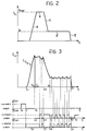
- Figure 3 shows the states of SW1, SW3 and the switch SW i associated with the load L i to be energised, and the corresponding actual behaviour of the current I Li in the load.
- the control unit ECU closes the switch SW1 at a time t o .
- the other switches remain open. In this condition, a current delivered by the battery V B flows into the storage inductor L1 and energy is stored.
- the switch SW1 is opened, whilst the switch SW i associated with the load to be energised is closed.
- the storage inductor L1 is connected to the capacitor C with which it forms a resonant circuit.
- This resonant circuit is discharged to the load L i associated with the switch SW i which is closed.
- the current in the storage inductor L i decreases whilst the current in the selected load L i increases from the time t1 to a maximum value which is reached at a time t2, and then starts to decline.
- the unit ECU changes the current I Li to the desired holding level by opening the switch SW i associated with the energised load and simultaneously closing SW3 (at the time indicated t3 in Figure 3): in this condition, the current flows in the loop formed by the energised load L i , the associated diode D c , the inductor L2, the switch SW3 and the diodes R2 and D BP .
- the unit ECU monitors the progressive decrease in the intensity of the current I Li by means of the sensor S.
- the unit ECU causes the switch SW i associated with the energised load and the switch SW3 to be opened and closed successively in counterphase, as shown in Figure 3 between the times t4 and t5.
- the unit ECU (at the time t5) simultaneously opens the switch SW i associated with the energised load and the switch SW3: the current flowing in the load is discharged and charges the capacitor C c and, after a certain time, at the time t6, the capacitor is discharged to the battery V B and the unit ECU then causes the closure of SW3.
- the inductor L2 serves to protect the switch SW3 by limiting the rate of variation of the current in the switch during energy recovery stages and particularly at the end of the de-activation cycle of each load.
Landscapes
- Engineering & Computer Science (AREA)
- Chemical & Material Sciences (AREA)
- Combustion & Propulsion (AREA)
- Mechanical Engineering (AREA)
- General Engineering & Computer Science (AREA)
- Electrical Control Of Air Or Fuel Supplied To Internal-Combustion Engine (AREA)
- Fuel-Injection Apparatus (AREA)
- Electronic Switches (AREA)
- High-Pressure Fuel Injection Pump Control (AREA)
Claims (3)
une alimentation à basse tension (VB),
des moyens de circuit réactif (L₁, C) comportant un inducteur (L₁) intercalé entre le premier pôle (1) de l'alimentation (VB) et la charge (Li),
un premier commutateur électronique (SW₁) en parallèle à un circuit de dérivation comprenant la charge (Li),
un deuxième commutateur électronique (SWi), en série avec la charge (Li), entre la charge (Li) et l'autre pôle (2) de l'alimentation (VB),
un troisième commutateur électronique (SW₃), intercalé entre le premier pôle (1) de l'alimentation (VB) et la jonction (N) entre la charge (Li) et le deuxième commutateur (SWi), et
une unité de commande électronique (ECU) qui, afin d'activer la charge (Li), est disposée de sorte à commander les commutateurs électroniques (SW₁, SWi, SW₃) d'une manière prédéterminée afin d'effectuer :
l'inducteur d'accumulation (L₁) est relié en permanence au premier pôle (1) de l'alimentation (VB), un chemin de dérivation conducteur (DBP) étant prévu entre le premier pôle (1) de l'alimentation (VB) et la charge (Li), et
l'unité de commande (ECU) est disposée de manière à ouvrir et fermer successivement en opposition de phase le second et le troisième commutateurs électroniques (SWi, SW₃), afin de maintenir le courant dans la charge (Li) au niveau moyen prédéterminé.
Priority Applications (1)
| Application Number | Priority Date | Filing Date | Title |
|---|---|---|---|
| AT89830459T ATE75002T1 (de) | 1988-10-27 | 1989-10-24 | Schaltung zum ansteuern von induktiven lasten, insbesondere zum antreiben von elektroeinspritzventilen eines dieselmotors. |
Applications Claiming Priority (2)
| Application Number | Priority Date | Filing Date | Title |
|---|---|---|---|
| IT6797088A IT1223872B (it) | 1988-10-27 | 1988-10-27 | Circuito per il pilotaggio di un carico induttivo in particolare per il comando degli elettroiniettori di un motore a ciclo diesel |
| IT6797088 | 1988-10-27 |
Publications (3)
| Publication Number | Publication Date |
|---|---|
| EP0366622A2 EP0366622A2 (fr) | 1990-05-02 |
| EP0366622A3 EP0366622A3 (en) | 1990-09-12 |
| EP0366622B1 true EP0366622B1 (fr) | 1992-04-15 |
Family
ID=11306834
Family Applications (1)
| Application Number | Title | Priority Date | Filing Date |
|---|---|---|---|
| EP19890830459 Expired - Lifetime EP0366622B1 (fr) | 1988-10-27 | 1989-10-24 | Circuit de commande de charges inductives, en particulier pour actionner des injecteurs électriques d'un moteur diesel |
Country Status (7)
| Country | Link |
|---|---|
| US (1) | US4950974A (fr) |
| EP (1) | EP0366622B1 (fr) |
| JP (1) | JPH02176139A (fr) |
| AT (1) | ATE75002T1 (fr) |
| DE (1) | DE68901248D1 (fr) |
| ES (1) | ES2030591T3 (fr) |
| IT (1) | IT1223872B (fr) |
Families Citing this family (36)
| Publication number | Priority date | Publication date | Assignee | Title |
|---|---|---|---|---|
| US5267545A (en) * | 1989-05-19 | 1993-12-07 | Orbital Engine Company (Australia) Pty. Limited | Method and apparatus for controlling the operation of a solenoid |
| DE3921308A1 (de) * | 1989-06-29 | 1991-01-10 | Bosch Gmbh Robert | Versorgungsschaltung fuer den betrieb eines elektromagnetischen verbrauchers |
| DE3939547C2 (de) * | 1989-11-30 | 1999-07-01 | Bosch Gmbh Robert | Vorrichtung zur Kraftstoffeinspritzung in Brennkraftmaschine |
| US5180964A (en) * | 1990-03-28 | 1993-01-19 | Ewing Gerald D | Zero-voltage switched FM-PWM converter |
| US5179508A (en) * | 1991-10-15 | 1993-01-12 | International Business Machines Corp. | Standby boost converter |
| IT1251259B (it) * | 1991-12-23 | 1995-05-05 | Elasis Sistema Ricerca Fiat | Circuito di comando di carichi prevalentemente induttivi, in particolare elettroiniettori. |
| JP3151932B2 (ja) * | 1992-04-27 | 2001-04-03 | ヤマハ株式会社 | 電源回路 |
| US5426559A (en) * | 1993-04-30 | 1995-06-20 | Chrysler Corporation | Control circuit for ignition spark in internal combustion engines |
| US5563781A (en) * | 1993-11-24 | 1996-10-08 | Integrated Technology Corporation | Dual-mode power converter |
| DE4415361B4 (de) * | 1994-05-02 | 2005-05-04 | Robert Bosch Gmbh | Verfahren und Vorrichtung zur Steuerung eines elektromagnetischen Verbrauchers |
| GB9422742D0 (en) * | 1994-11-11 | 1995-01-04 | Lucas Ind Plc | Drive circuit |
| WO1996027198A1 (fr) * | 1995-03-02 | 1996-09-06 | Robert Bosch Gmbh | Dispositif servant a la commande d'au moins un consommateur electromagnetique |
| US5687050A (en) * | 1995-07-25 | 1997-11-11 | Ficht Gmbh | Electronic control circuit for an internal combustion engine |
| IT1284693B1 (it) * | 1996-07-23 | 1998-05-21 | Fiat Ricerche | Dispositivo di controllo di carichi induttivi, in paricolare di iniettori in un impianto di iniezione per un motore a combustione |
| EP0847063B1 (fr) * | 1996-11-29 | 2002-06-05 | Denso Corporation | Dispositif de commande d'une électrovanne |
| US5752482A (en) * | 1997-03-28 | 1998-05-19 | Cummins Engine Company, Inc. | System for integrally controlling current flow through number of inductive loads |
| US6075295A (en) * | 1997-04-14 | 2000-06-13 | Micro Linear Corporation | Single inductor multiple output boost regulator |
| US5889645A (en) * | 1997-04-14 | 1999-03-30 | International Controls And Measurement Corp | Energy preservation and transfer mechanism |
| US5979412A (en) * | 1997-08-12 | 1999-11-09 | Walbro Corporation | Inductive discharge injector driver |
| US6005763A (en) * | 1998-02-20 | 1999-12-21 | Sturman Industries, Inc. | Pulsed-energy controllers and methods of operation thereof |
| DE19812744A1 (de) * | 1998-03-24 | 1999-09-30 | Bosch Gmbh Robert | Verfahren und Vorrichtung zum Schalten eines induktiven Verbrauchers |
| DE19812742A1 (de) * | 1998-03-24 | 1999-09-30 | Bosch Gmbh Robert | Verfahren und Vorrichtung zum Schalten einer Induktivität |
| US6344980B1 (en) | 1999-01-14 | 2002-02-05 | Fairchild Semiconductor Corporation | Universal pulse width modulating power converter |
| US6166455A (en) * | 1999-01-14 | 2000-12-26 | Micro Linear Corporation | Load current sharing and cascaded power supply modules |
| US6091233A (en) * | 1999-01-14 | 2000-07-18 | Micro Linear Corporation | Interleaved zero current switching in a power factor correction boost converter |
| DE19922485B4 (de) * | 1999-05-15 | 2008-06-12 | Robert Bosch Gmbh | Verfahren und Schaltungsanordnung zur Ansteuerung eines Doppelspulen-Hochdruckeinspritzmagnetventils für die Kraftstoffeinspritzung |
| ITBO20000489A1 (it) * | 2000-08-04 | 2002-02-04 | Magneti Marelli Spa | Metodo e dispositivo per il pilotaggio di un iniettore in un motore acombustione interna . |
| US6684854B2 (en) | 2001-12-14 | 2004-02-03 | Caterpillar Inc | Auxiliary systems for an engine having two electrical actuators on a single circuit |
| US6806446B1 (en) * | 2002-10-04 | 2004-10-19 | Stephen D. Neale | Power management controls for electric appliances |
| JP2004197629A (ja) * | 2002-12-18 | 2004-07-15 | Denso Corp | 電磁負荷駆動装置 |
| US6953108B2 (en) | 2003-04-04 | 2005-10-11 | Millenworks | Magnetorheological damper system |
| US7057870B2 (en) * | 2003-07-17 | 2006-06-06 | Cummins, Inc. | Inductive load driver circuit and system |
| JP5966308B2 (ja) * | 2011-10-13 | 2016-08-10 | 富士電機株式会社 | 誘導性負荷制御装置 |
| US10075007B2 (en) * | 2014-09-02 | 2018-09-11 | Apple Inc. | Multi-phase battery charging with boost bypass |
| US10097017B2 (en) | 2015-06-24 | 2018-10-09 | Apple Inc. | Systems and methods for bidirectional two-port battery charging with boost functionality |
| US10778026B2 (en) | 2016-09-23 | 2020-09-15 | Apple Inc. | Multi-phase buck-boost charger |
Family Cites Families (6)
| Publication number | Priority date | Publication date | Assignee | Title |
|---|---|---|---|---|
| DE2900420A1 (de) * | 1979-01-08 | 1980-07-24 | Bosch Gmbh Robert | Einrichtung zum steuern des stromes durch einen elektromagnetischen verbraucher, insbesondere durch ein elektromagnetisch betaetigbares einspritzventil einer brennkraftmaschine |
| FR2533263B1 (fr) * | 1982-09-16 | 1987-03-20 | Renault | Dispositif de commande d'organes electromagnetiques a actionnement rapide, tels qu'electrovannes ou injecteurs pour moteurs a combustion interne |
| US4618908A (en) * | 1985-08-05 | 1986-10-21 | Motorola, Inc. | Injector driver control unit with internal overvoltage protection |
| JPS6380038A (ja) * | 1986-09-19 | 1988-04-11 | Nippon Denso Co Ltd | 電磁弁駆動回路 |
| US4862866A (en) * | 1987-08-25 | 1989-09-05 | Marelli Autronica S.P.A. | Circuit for the piloting of inductive loads, particularly for operating the electro-injectors of a diesel-cycle internal combustion engine |
| JPH077367A (ja) * | 1993-06-16 | 1995-01-10 | Tdk Corp | 圧電共振部品 |
-
1988
- 1988-10-27 IT IT6797088A patent/IT1223872B/it active
-
1989
- 1989-10-24 AT AT89830459T patent/ATE75002T1/de not_active IP Right Cessation
- 1989-10-24 EP EP19890830459 patent/EP0366622B1/fr not_active Expired - Lifetime
- 1989-10-24 ES ES89830459T patent/ES2030591T3/es not_active Expired - Lifetime
- 1989-10-24 DE DE8989830459T patent/DE68901248D1/de not_active Expired - Lifetime
- 1989-10-25 US US07/426,266 patent/US4950974A/en not_active Expired - Fee Related
- 1989-10-26 JP JP1279613A patent/JPH02176139A/ja active Pending
Also Published As
| Publication number | Publication date |
|---|---|
| ATE75002T1 (de) | 1992-05-15 |
| ES2030591T3 (es) | 1992-11-01 |
| EP0366622A2 (fr) | 1990-05-02 |
| IT8867970A0 (it) | 1988-10-27 |
| US4950974A (en) | 1990-08-21 |
| JPH02176139A (ja) | 1990-07-09 |
| EP0366622A3 (en) | 1990-09-12 |
| IT1223872B (it) | 1990-09-29 |
| DE68901248D1 (de) | 1992-05-21 |
Similar Documents
| Publication | Publication Date | Title |
|---|---|---|
| EP0366622A2 (fr) | Circuit de commande de charges inductives, en particulier pour actionner des injecteurs électriques d'un moteur diesel | |
| US6250286B1 (en) | Method and device for controlling at least one solenoid valve | |
| KR100385746B1 (ko) | 전력 출력단을 제어하는 방법 및 장치 | |
| US6353307B1 (en) | Controlled rectifier bridge with over-voltage protection | |
| EP0763882B1 (fr) | Dispositif d'attaque de charge | |
| US5907466A (en) | Device and process for activating at least two electromagnetic loads | |
| US5936827A (en) | Device for controlling at least one electromagnetic load | |
| US4933805A (en) | Circuit for controlling inductive loads, particularly for the operation of the electro-injectors of a diesel-engine | |
| US4314305A (en) | Solenoid drive circuits | |
| EP2286507B1 (fr) | Système de commande de solénoïde basse puissance et procédé | |
| EP0924589A1 (fr) | Appareil de commande pour un actionneur électrique et méthode pour commander cet appareil de commande | |
| US5341082A (en) | Reverse current flow protector for electricity storage systems | |
| US5218339A (en) | Arrangement for monitoring a consumer in combination with an internal combustion engine and/or a motor vehicle | |
| US4770178A (en) | Method and circuit arrangement for controlling an injection valve | |
| EP0305344B1 (fr) | Circuit de commande de charges inductives, en particulier pour actionner des injecteurs électriques d'un moteur diesel | |
| KR100413401B1 (ko) | 전자기부하용전력단부스테이지및이를트리거링하기위한방법 | |
| EP0740073A1 (fr) | Circuit pour détecter une surtension dans un charge électrique | |
| US4967718A (en) | Ignition system for an internal combustion engine using thyristors | |
| US7382065B2 (en) | Circuit for controlling inductive loads, in particular of electro actuators, at high efficiency | |
| KR980012779A (ko) | 차량용 교류 발전기의 제어 장치 | |
| US4965696A (en) | Voltage doubling driving circuit for controlling a field effect transistor having a source load | |
| GB2319415A (en) | Fuel injector driver with premagnetisation phase | |
| US5602505A (en) | Gate drive circuit | |
| RU2074430C1 (ru) | Электромагнитный привод коммутационного аппарата | |
| EP0821149A1 (fr) | Appareil de commande de charges inductives, en particulier pour injecteurs de systèmes à injection de moteur à combustion interne |
Legal Events
| Date | Code | Title | Description |
|---|---|---|---|
| PUAI | Public reference made under article 153(3) epc to a published international application that has entered the european phase |
Free format text: ORIGINAL CODE: 0009012 |
|
| AK | Designated contracting states |
Kind code of ref document: A2 Designated state(s): AT BE CH DE ES FR GB GR IT LI LU NL SE |
|
| PUAL | Search report despatched |
Free format text: ORIGINAL CODE: 0009013 |
|
| AK | Designated contracting states |
Kind code of ref document: A3 Designated state(s): AT BE CH DE ES FR GB GR IT LI LU NL SE |
|
| 17P | Request for examination filed |
Effective date: 19901220 |
|
| 17Q | First examination report despatched |
Effective date: 19910503 |
|
| RAP1 | Party data changed (applicant data changed or rights of an application transferred) |
Owner name: MARELLI AUTRONICA S.P.A. |
|
| GRAA | (expected) grant |
Free format text: ORIGINAL CODE: 0009210 |
|
| AK | Designated contracting states |
Kind code of ref document: B1 Designated state(s): AT BE CH DE ES FR GB GR IT LI LU NL SE |
|
| PG25 | Lapsed in a contracting state [announced via postgrant information from national office to epo] |
Ref country code: IT Free format text: LAPSE BECAUSE OF FAILURE TO SUBMIT A TRANSLATION OF THE DESCRIPTION OR TO PAY THE FEE WITHIN THE PRE;WARNING: LAPSES OF ITALIAN PATENTS WITH EFFECTIVE DATE BEFORE 2007 MAY HAVE OCCURRED AT ANY TIME BEFORE 2007. THE CORRECT EFFECTIVE DATE MAY BE DIFFERENT FROM THE ONE RECORDED.SCRIBED TIME-LIMIT Effective date: 19920415 Ref country code: GR Free format text: LAPSE BECAUSE OF FAILURE TO SUBMIT A TRANSLATION OF THE DESCRIPTION OR TO PAY THE FEE WITHIN THE PRESCRIBED TIME-LIMIT Effective date: 19920415 |
|
| REF | Corresponds to: |
Ref document number: 75002 Country of ref document: AT Date of ref document: 19920515 Kind code of ref document: T |
|
| REF | Corresponds to: |
Ref document number: 68901248 Country of ref document: DE Date of ref document: 19920521 |
|
| ET | Fr: translation filed | ||
| PG25 | Lapsed in a contracting state [announced via postgrant information from national office to epo] |
Ref country code: LU Free format text: LAPSE BECAUSE OF NON-PAYMENT OF DUE FEES Effective date: 19921031 |
|
| REG | Reference to a national code |
Ref country code: ES Ref legal event code: FG2A Ref document number: 2030591 Country of ref document: ES Kind code of ref document: T3 |
|
| PLBE | No opposition filed within time limit |
Free format text: ORIGINAL CODE: 0009261 |
|
| STAA | Information on the status of an ep patent application or granted ep patent |
Free format text: STATUS: NO OPPOSITION FILED WITHIN TIME LIMIT |
|
| 26N | No opposition filed | ||
| EAL | Se: european patent in force in sweden |
Ref document number: 89830459.7 |
|
| PGFP | Annual fee paid to national office [announced via postgrant information from national office to epo] |
Ref country code: AT Payment date: 19990914 Year of fee payment: 11 |
|
| PGFP | Annual fee paid to national office [announced via postgrant information from national office to epo] |
Ref country code: NL Payment date: 19990921 Year of fee payment: 11 |
|
| PGFP | Annual fee paid to national office [announced via postgrant information from national office to epo] |
Ref country code: BE Payment date: 19991004 Year of fee payment: 11 |
|
| PG25 | Lapsed in a contracting state [announced via postgrant information from national office to epo] |
Ref country code: AT Free format text: LAPSE BECAUSE OF NON-PAYMENT OF DUE FEES Effective date: 20001024 |
|
| PG25 | Lapsed in a contracting state [announced via postgrant information from national office to epo] |
Ref country code: BE Free format text: LAPSE BECAUSE OF NON-PAYMENT OF DUE FEES Effective date: 20001031 |
|
| BERE | Be: lapsed |
Owner name: MARELLI AUTRONICA S.P.A. Effective date: 20001031 |
|
| PG25 | Lapsed in a contracting state [announced via postgrant information from national office to epo] |
Ref country code: NL Free format text: LAPSE BECAUSE OF NON-PAYMENT OF DUE FEES Effective date: 20010501 |
|
| NLV4 | Nl: lapsed or anulled due to non-payment of the annual fee |
Effective date: 20010501 |
|
| REG | Reference to a national code |
Ref country code: GB Ref legal event code: IF02 |
|
| PGFP | Annual fee paid to national office [announced via postgrant information from national office to epo] |
Ref country code: ES Payment date: 20060904 Year of fee payment: 18 |
|
| PGFP | Annual fee paid to national office [announced via postgrant information from national office to epo] |
Ref country code: GB Payment date: 20060914 Year of fee payment: 18 |
|
| PGFP | Annual fee paid to national office [announced via postgrant information from national office to epo] |
Ref country code: CH Payment date: 20060918 Year of fee payment: 18 |
|
| PGFP | Annual fee paid to national office [announced via postgrant information from national office to epo] |
Ref country code: DE Payment date: 20060925 Year of fee payment: 18 |
|
| PGFP | Annual fee paid to national office [announced via postgrant information from national office to epo] |
Ref country code: FR Payment date: 20061031 Year of fee payment: 18 |
|
| PGFP | Annual fee paid to national office [announced via postgrant information from national office to epo] |
Ref country code: SE Payment date: 20060831 Year of fee payment: 18 |
|
| EUG | Se: european patent has lapsed | ||
| GBPC | Gb: european patent ceased through non-payment of renewal fee |
Effective date: 20071024 |
|
| REG | Reference to a national code |
Ref country code: CH Ref legal event code: PL |
|
| PG25 | Lapsed in a contracting state [announced via postgrant information from national office to epo] |
Ref country code: LI Free format text: LAPSE BECAUSE OF NON-PAYMENT OF DUE FEES Effective date: 20071031 Ref country code: DE Free format text: LAPSE BECAUSE OF NON-PAYMENT OF DUE FEES Effective date: 20080501 Ref country code: CH Free format text: LAPSE BECAUSE OF NON-PAYMENT OF DUE FEES Effective date: 20071031 |
|
| REG | Reference to a national code |
Ref country code: FR Ref legal event code: ST Effective date: 20080630 |
|
| PG25 | Lapsed in a contracting state [announced via postgrant information from national office to epo] |
Ref country code: SE Free format text: LAPSE BECAUSE OF NON-PAYMENT OF DUE FEES Effective date: 20071025 |
|
| PG25 | Lapsed in a contracting state [announced via postgrant information from national office to epo] |
Ref country code: GB Free format text: LAPSE BECAUSE OF NON-PAYMENT OF DUE FEES Effective date: 20071024 |
|
| REG | Reference to a national code |
Ref country code: ES Ref legal event code: FD2A Effective date: 20071025 |
|
| PG25 | Lapsed in a contracting state [announced via postgrant information from national office to epo] |
Ref country code: ES Free format text: LAPSE BECAUSE OF NON-PAYMENT OF DUE FEES Effective date: 20071025 Ref country code: FR Free format text: LAPSE BECAUSE OF NON-PAYMENT OF DUE FEES Effective date: 20071031 |