EP0366678B1 - Fixateur a anneaux d'ajustement, de fixation et de reglage de la position de serrage de sections d'os - Google Patents
Fixateur a anneaux d'ajustement, de fixation et de reglage de la position de serrage de sections d'os Download PDFInfo
- Publication number
- EP0366678B1 EP0366678B1 EP88905179A EP88905179A EP0366678B1 EP 0366678 B1 EP0366678 B1 EP 0366678B1 EP 88905179 A EP88905179 A EP 88905179A EP 88905179 A EP88905179 A EP 88905179A EP 0366678 B1 EP0366678 B1 EP 0366678B1
- Authority
- EP
- European Patent Office
- Prior art keywords
- ring
- wires
- struts
- strut
- wire
- Prior art date
- Legal status (The legal status is an assumption and is not a legal conclusion. Google has not performed a legal analysis and makes no representation as to the accuracy of the status listed.)
- Expired - Lifetime
Links
- 210000000988 bone and bone Anatomy 0.000 title claims abstract description 45
- 239000000969 carrier Substances 0.000 claims abstract 2
- 230000008878 coupling Effects 0.000 claims description 24
- 238000010168 coupling process Methods 0.000 claims description 24
- 238000005859 coupling reaction Methods 0.000 claims description 24
- 230000001681 protective effect Effects 0.000 claims description 6
- 239000000835 fiber Substances 0.000 claims description 3
- 239000011159 matrix material Substances 0.000 claims description 3
- 239000004033 plastic Substances 0.000 claims description 3
- 229920003023 plastic Polymers 0.000 claims description 3
- 238000010276 construction Methods 0.000 claims description 2
- 230000000149 penetrating effect Effects 0.000 claims description 2
- 238000003780 insertion Methods 0.000 claims 2
- 230000037431 insertion Effects 0.000 claims 1
- 230000007246 mechanism Effects 0.000 claims 1
- 230000008901 benefit Effects 0.000 description 24
- 238000000034 method Methods 0.000 description 15
- 239000012634 fragment Substances 0.000 description 10
- 238000013461 design Methods 0.000 description 9
- 208000027418 Wounds and injury Diseases 0.000 description 7
- 238000006073 displacement reaction Methods 0.000 description 7
- 238000005553 drilling Methods 0.000 description 7
- 208000014674 injury Diseases 0.000 description 7
- 230000008569 process Effects 0.000 description 7
- 230000015572 biosynthetic process Effects 0.000 description 6
- 230000006378 damage Effects 0.000 description 6
- 238000005755 formation reaction Methods 0.000 description 6
- 238000002560 therapeutic procedure Methods 0.000 description 6
- 230000008859 change Effects 0.000 description 5
- 230000035876 healing Effects 0.000 description 5
- 230000036961 partial effect Effects 0.000 description 5
- 238000004873 anchoring Methods 0.000 description 4
- 238000005452 bending Methods 0.000 description 4
- 238000012937 correction Methods 0.000 description 3
- 230000003993 interaction Effects 0.000 description 3
- 230000035515 penetration Effects 0.000 description 3
- 210000004872 soft tissue Anatomy 0.000 description 3
- 238000003860 storage Methods 0.000 description 3
- 208000010392 Bone Fractures Diseases 0.000 description 2
- 206010017076 Fracture Diseases 0.000 description 2
- 230000006978 adaptation Effects 0.000 description 2
- 230000000712 assembly Effects 0.000 description 2
- 238000000429 assembly Methods 0.000 description 2
- 230000001042 autoregulative effect Effects 0.000 description 2
- 239000008280 blood Substances 0.000 description 2
- 210000004369 blood Anatomy 0.000 description 2
- UQMRAFJOBWOFNS-UHFFFAOYSA-N butyl 2-(2,4-dichlorophenoxy)acetate Chemical compound CCCCOC(=O)COC1=CC=C(Cl)C=C1Cl UQMRAFJOBWOFNS-UHFFFAOYSA-N 0.000 description 2
- 239000002131 composite material Substances 0.000 description 2
- 230000006835 compression Effects 0.000 description 2
- 238000007906 compression Methods 0.000 description 2
- 239000003814 drug Substances 0.000 description 2
- 230000000694 effects Effects 0.000 description 2
- 238000002690 local anesthesia Methods 0.000 description 2
- 230000011164 ossification Effects 0.000 description 2
- 230000002829 reductive effect Effects 0.000 description 2
- 230000001105 regulatory effect Effects 0.000 description 2
- 238000007493 shaping process Methods 0.000 description 2
- 238000001356 surgical procedure Methods 0.000 description 2
- 230000001225 therapeutic effect Effects 0.000 description 2
- 210000001519 tissue Anatomy 0.000 description 2
- 230000009466 transformation Effects 0.000 description 2
- 241001136792 Alle Species 0.000 description 1
- 206010010356 Congenital anomaly Diseases 0.000 description 1
- 206010020649 Hyperkeratosis Diseases 0.000 description 1
- 206010023230 Joint stiffness Diseases 0.000 description 1
- 208000004221 Multiple Trauma Diseases 0.000 description 1
- 208000006670 Multiple fractures Diseases 0.000 description 1
- 208000023637 Multiple injury Diseases 0.000 description 1
- 241000207836 Olea <angiosperm> Species 0.000 description 1
- 240000007817 Olea europaea Species 0.000 description 1
- 206010039203 Road traffic accident Diseases 0.000 description 1
- 230000001154 acute effect Effects 0.000 description 1
- 210000001185 bone marrow Anatomy 0.000 description 1
- 230000001364 causal effect Effects 0.000 description 1
- 230000001427 coherent effect Effects 0.000 description 1
- 210000002808 connective tissue Anatomy 0.000 description 1
- 238000007596 consolidation process Methods 0.000 description 1
- 239000004035 construction material Substances 0.000 description 1
- 230000007547 defect Effects 0.000 description 1
- 238000011161 development Methods 0.000 description 1
- 230000018109 developmental process Effects 0.000 description 1
- 239000000428 dust Substances 0.000 description 1
- 230000008030 elimination Effects 0.000 description 1
- 238000003379 elimination reaction Methods 0.000 description 1
- 238000004880 explosion Methods 0.000 description 1
- 238000009432 framing Methods 0.000 description 1
- 238000002695 general anesthesia Methods 0.000 description 1
- 230000012447 hatching Effects 0.000 description 1
- 208000015181 infectious disease Diseases 0.000 description 1
- 238000009434 installation Methods 0.000 description 1
- 230000001788 irregular Effects 0.000 description 1
- 210000005067 joint tissue Anatomy 0.000 description 1
- 238000004519 manufacturing process Methods 0.000 description 1
- 239000000463 material Substances 0.000 description 1
- 230000005541 medical transmission Effects 0.000 description 1
- 239000000203 mixture Substances 0.000 description 1
- 210000005036 nerve Anatomy 0.000 description 1
- 238000006386 neutralization reaction Methods 0.000 description 1
- 235000016709 nutrition Nutrition 0.000 description 1
- 230000000399 orthopedic effect Effects 0.000 description 1
- 238000003825 pressing Methods 0.000 description 1
- 230000002250 progressing effect Effects 0.000 description 1
- 230000002035 prolonged effect Effects 0.000 description 1
- 238000002278 reconstructive surgery Methods 0.000 description 1
- 230000011514 reflex Effects 0.000 description 1
- 230000001172 regenerating effect Effects 0.000 description 1
- 230000002441 reversible effect Effects 0.000 description 1
- 230000006641 stabilisation Effects 0.000 description 1
- 238000011105 stabilization Methods 0.000 description 1
- 230000000087 stabilizing effect Effects 0.000 description 1
- 230000004083 survival effect Effects 0.000 description 1
- 238000012360 testing method Methods 0.000 description 1
- 230000025366 tissue development Effects 0.000 description 1
- 230000009772 tissue formation Effects 0.000 description 1
- 230000017423 tissue regeneration Effects 0.000 description 1
- 238000012546 transfer Methods 0.000 description 1
- 230000008733 trauma Effects 0.000 description 1
- 230000003144 traumatizing effect Effects 0.000 description 1
- 230000002792 vascular Effects 0.000 description 1
- XLYOFNOQVPJJNP-UHFFFAOYSA-N water Substances O XLYOFNOQVPJJNP-UHFFFAOYSA-N 0.000 description 1
- 230000003313 weakening effect Effects 0.000 description 1
- 239000013585 weight reducing agent Substances 0.000 description 1
Images


Classifications
-
- A—HUMAN NECESSITIES
- A61—MEDICAL OR VETERINARY SCIENCE; HYGIENE
- A61B—DIAGNOSIS; SURGERY; IDENTIFICATION
- A61B17/00—Surgical instruments, devices or methods
- A61B17/56—Surgical instruments or methods for treatment of bones or joints; Devices specially adapted therefor
- A61B17/58—Surgical instruments or methods for treatment of bones or joints; Devices specially adapted therefor for osteosynthesis, e.g. bone plates, screws or setting implements
- A61B17/60—Surgical instruments or methods for treatment of bones or joints; Devices specially adapted therefor for osteosynthesis, e.g. bone plates, screws or setting implements for external osteosynthesis, e.g. distractors, contractors
- A61B17/62—Ring frames, i.e. devices extending around the bones to be positioned
Definitions
- the invention relates to a ring fixator composed of parts of a kit for setting up, fastening and regulating the clamping position of bone sections according to the preamble of claim 1.
- Such devices are known as compression and distraction devices, in particular by GA Ilisarov and the USSR Patent No. 5387103338801 / 28-13 and Italian patent no. 47890-A / 82.
- fixators made of rings and / or ring sections, in which in each ring or ring section plane pairs or singular tension wires are arranged for bone fixation, the different rings being connected by rods and the ring plane spacing by different lengths or telescopically adjustable rods can be adjusted.
- These bone fixations using a cylindrical frame and transosseous tension wires according to Ilisarov have proven to be superior to polygonal frame fixators or rod fixators positioned paraxial to the bone.
- transosseous ring-wire fixations can be applied on an outpatient basis and under local anesthesia. They can be used to carry out three-dimensional bone arrangements in a stereognostically clear manner and secondary straightening work can also be carried out clearly. Without endangering the nutritional situation of the tissues and without the risk of weakening the stability, any wires can also be attached, removed or replaced afterwards if necessary.
- treatment in such ring-wire fixators is designed as a prolonged, continuously progressing surgical process. Failures that would have to be related to an operation that was unsuccessful or incorrect at a certain point in time are always procedural due to the procedural feature available correction option outside the procedure.
- Ilisarov's ring fixation techniques are largely subordinate to the biological healing process, because early method-related stress on the limbs represents the process information of callus formation and bone transformation that can be evaluated by the self-organizing, autoregulatory nature. After all, the flow of force in such concentrically positioned fractures or osteotomies is maintained in a stress-specific manner, whereupon in the course of self-organizational-autoregulative consolidation, construction materials in the fracture or osteotomy zone can be differentiated locally and selectively according to pressure and tensile strength, and arranged in a stress-specific manner.
- ring fixators as external stabilization scaffolds are resistant to compression, bending and torsion due to their cylindrical structure, and that bendable penetrating wires serve as very stable anchoring bearings, can stimulate tissue formation and reshaping processes based on controllable flexibility of the wires within the framework of a physiological reaction range reparative and generative new bone formations can be controlled therapeutically.
- the Ilisarov rings can be set up for most stereometric situations.
- many changes in shape and tension cannot be carried out with sufficient precision and, with regard to the frequency of the necessary correction steps, cannot be carried out with the desired simplicity and time saving.
- the continuity of this externally and dynamically fixing osteosynthesis therapy which is necessary for the procedural healing process, cannot be reliably guaranteed.
- a ring fixator with improved maneuverability has become known from DE-OS 34 39 795, which describes a device for setting up bone sections and / or fragments in which the connecting rods between the rings can be pivoted on all sides within predetermined but small limits are mounted on the rings and can be locked in any swivel position, whereby the distances between the adjacent rings can be set on different levels independently of the swivel positions of the rods, although the entire circumference of the rings is not available for localizing the connecting rods, but only on certain ring circumference is limited, which are determined by a series of holes.
- the rings are transversely lying cut-outs of a disturbingly large outer circumference.
- the connecting rods between two rings can only be located at predetermined locations on the rings, as a result of which it is not possible for the ends of the connecting rods to move freely on the rings.
- the spatial wire routing for the tensioning wires of the known apparatus is insufficient because the tensioning wires can practically only be tensioned in the direction of the diameter, and eccentric wire layers are associated with a risky kinking of the wires.
- EP-A3-0146872 discloses a device for setting up bone sections and / or bone fragments, which consists of adjusting rings which can be connected to one another by rods and fastening means at adjustable and adjustable intervals, and of tensioning wires which extend in the planes spanned by the adjusting rings and with their ends by means of brackets can be fastened to parts that are distant from one another under longitudinal tension.
- the fastening of the tension wire ends to the adjusting rings is used for adjustable tensioning elements.
- the rods are continuously axially movable in the fastening elements for connecting adjacent adjusting rings and, independently of this, are continuously and angularly movable within predetermined limits and locked in all setting positions.
- the tension wires can only be held in the diameter direction, the cross formed by two tension wires cannot be moved arbitrarily in the plane of the ring.
- a device for external fixation of bone segments which contains at least two rings on which crossing Kirschner wires are tensioned.
- the rings are held at an adjustable distance with bars distributed over their circumference.
- Infinitely adjustable holders which project radially outwards from the rings, are used to attach the rods.
- At the end of the holder is a joint receiving the rod with freedom of rotation about at least two mutually perpendicular axes.
- a spring tensioner with adjustable spring force acting in the longitudinal direction of the rod is connected between the rings on each rod.
- This ring fixator has essentially the same disadvantages as have been described in the ring fixator of DE-OS 34 39 795.
- a ring fixator which consists of rings with a circular cross-section which are connected to one another by longitudinal struts.
- the struts each have a hemisphere with a corrugated surface with the normal perpendicular to the strut at both ends, this surface being opposed by a similarly designed hemisphere with a corrugated surface, which is an integral part of a bolt holder that can be clamped to the ring.
- a screw is screwed through both hemispheres for the frictional connection of one end of the rod to the bolt holder, so that the rod can be moved by one degree of freedom within the bolt holder.
- the other end of the bolt holder sits in one Screw clamp, which is able to grip either the ring or another strut in a clamping manner.
- the screw terminals Similar to the half shells, the screw terminals have a corrugated contact surface on the side, which is used to clamp two screw terminals with a long screw at the same time, the two screw terminals being rotatable by an angle of 360 degrees to one another.
- This allows a certain parallel displacement of the rings and the struts to each other.
- the respective continuous screw in order to adjust the struts to the ring brackets, as well as the screw terminals with one another, the respective continuous screw must be completely loosened in order to change the angular position due to the corrugation of the surfaces pressing against one another.
- the tension relationships built up with the ring fixator can change in an uncontrollable manner.
- the maneuverability of the individual parts relative to one another is limited to the arbitrary adjustability of the ring fixator; There is no linear locking in the pivot bearings of the struts.
- the invention is therefore based on an overall task, which is subdivided into three subtasks, to form an improved ring fixator of the type mentioned at the beginning; there is a stereometric, a dynamometric and a tactical subtask.
- the stereometric subtask requires the stepless adjustability of the lengths as well as the angular positions of the struts relative to the ring and partial ring planes, as well as the arbitrary location on the rings for fastening the strut and wire holders and the arbitrary location for wire fastenings between the rings and on the Strive for yourself.
- the dynamometric subtask demands the possibility of setting all clamping positions that are to be applied between ring fixator parts themselves and also all clamping positions that result from the composite between the ring fixator on the one hand and the bone or soft tissue on the other hand result in such a way that they can be carried out continuously and without the addition of an additional tensioning device.
- the tactical subtask demands such simplicity of operation that with ring fixator assembly at the start of therapy as well as during the entire therapeutic fixation phase in the ring fixator, all stereometrically fixing and all dynamometrically exciting measures with a few similarly repeated hand movements of adjustment and tensioning on all to be moved and force receiving parts are executable, the supplementary use, removal or exchange of brackets, partial rings, struts and wires should be carried out individually in the ring-radial assembly direction - without disturbing the rest of the fixation arrangement.
- a first decisive advantage of the device according to the invention arises from the wires which are designed as threaded wires with continuously extending threads for screwing on the clamping and position nuts.
- the tension of the wires is achieved without the need for separate external tensioning means.
- ring fixers have to be able to adapt stereometrically and dynamometrically to the natural healing processes; This means that both the position and the tension of each individual wire must be adjustable in terms of process. Since, according to the method, these corrections often have to be carried out in small steps - usually daily - the simple tension-regulating turning of the wire tensioning screws according to the invention means that for the first time practical implementation of procedural osteosynthesis techniques per se.
- the threading of the wires is advantageous because during wire drilling, which can be carried out in opposite directions, i.e. for right-hand wire threads with left-handed wire twisting, the wire threads cause the resulting bone drilling dust to be transported back and because in this way the borehole walls are caused by flowing blood and Protect tissue water from excessive drilling heat.
- the threaded wires are also advantageous because the position nuts of the invention, which are polyhedral and angular on the surface and can be locked against rotation, can be screwed onto any surface of the wires according to the invention - surface-smooth at Ilisarov, metallically connected to the wires and referred to as "olives" - and thus because of this the stocking with special "olive wires" can be omitted.
- the thread formation is also advantageous because the wires over the spherically mounted clamping nuts in pivoted, yet kink-free clamping positions can be brought.
- Another decisive advantage of the device according to the invention is based on the wire bearings for connecting these threaded wires to the rings and ring parts or the struts by the fact that they consist of U-shaped tabs which can be clamped in a flush manner and which are on the circumference of the rings or on the struts in a ring radius.
- Direction or in a direction rotated by 90 degrees for this purpose can be plugged in, removed and locked and can still be freely moved but also clamped in the locking.
- the advantage of arbitrary U-rider displaceability instead of the usual attachment of wire holders to predetermined storage locations is that this free choice of attachment always offers the possibility of wire penetration locations that are anatomotopographically dangerous when drilling the wire and -to avoid directions.
- a finely tunable wire placement is also an advantage.
- the freedom of choice of the wire layers also has a significant advantage in terms of dynamometry, because the absence of tension in the wires must always be the starting point for a completed ring-wire fixator assembly if stereometric and dynamometric maneuvers are to bring about therapeutically accurate and no other tension loads and to transfer them to the bone fragment constellation.
- wire bearings according to the invention Another advantage of these wire bearings according to the invention is that that wires bent or bending under load or changing their deflection under tension increase do not kink, since they can be inserted through spherical support surfaces of selectable length and detachably connected to the U-riders and can be pivotally supported in it in three dimensions.
- This pivotable storage ability of the threaded wires and their tension in the pivoted position without kinking is only possible through the inventive design of tension nuts with spherical bearing surfaces.
- these ball head clamping nuts can also serve as protection against injury with their ball head turned outwards. In contrast, it is necessary with conventional wires to bend the ends, which makes the wires practically unusable for re-tensioning.
- these perforated bearings can be rotated about their longitudinal axis, can be fastened and exchanged in any rotational position. Depending on requirements, shorter, longer plug-in perforated bearings can be exchanged and vice versa. If it is necessary to replace the wire and exchange the hole bearings, the new wire hole, which deliberately distances itself from a bone perforation to be abandoned, can again be made at an anatomically harmless location.
- wire bearings according to the invention are their U-shaped symmetry. If necessary, one wire can be clamped in one and the same U-tab on both sides of a ring or a strut. This also applies to the clamping forces
- the position of symmetry has the effect that the oppositely directed torques emanating from the wires are neutralized, so that consequently undesired deformations on the ring fixator framework can be avoided and high therapeutically usable clamping loads can be applied.
- a significant advantage is also the usability of the U-rider for fastening the strut bearings according to the invention.
- To assemble it is only necessary to use pluggable coupling elements which are inserted with correspondingly shaped ends into the sockets of the U-riders and into the clamping brackets of the strut bearings.
- This type of strut attachment advantageously provides the possibility of using one or two wire bearings on one and the same U-rider, either one or two wires or one or two coupling members, or one or two strut bearings or, in a mixed combination, one wire bearing and one strut bearing to attach the U-rider to a ring site.
- a further advantage is that a complete strut dismantling which destabilizes the ring assembly is not necessary in order to carry out deviating strut transverse displacements, but merely a frictional loosening of the clamping tension of the U-riders on the ring.
- struts with slot-shaped recesses arranged in the strut axis and with interchangeable, spindle-shaped sections for their adaptation to ring floors which are variable in their spacing.
- These recesses can have longitudinal slots between two partial struts or a row of struts arranged in the center line of the struts There are perforations through which fixation and steering wires can be inserted and swiveled.
- a significant stereometric advantage is the position and direction of the wire layers in the intermediate area between the rings, which can be freely determined by the interaction of the strut slots, the rotatable spindle-shaped strut sections and by the pivoting wire tension nuts.
- the interchangeable spindle-shaped strut sections bring not only the axial rotatability and the collet-like clamping ability of the spindles, but also the advantage that in co-operation with the longitudinal bearings of the struts, which are still to be described, coarse and fine length adjustments of the struts can be made by telescopic screwing.
- the strut bearings for connecting the struts to the rings and / or ring sections have clamping sleeves for flat locking and stepless adjustment, which enable both length and three-dimensional angle-adjusting settings of the struts, the settings for linear degrees of freedom being able to be carried out separately from settings for rotational degrees of freedom.
- the areal clamping connection which is to be made non-slip against shear forces, is achieved in each case by collet-like slits in the clamping sleeves with the formation of half-shells, both on the length-adapting axle bearing and on the angle-adapting ball bearing.
- Tension screws which are mounted in aligned flange bores of the adapter sleeves, provide the required clamping tensions with an advantageous ring-radial access path.
- the stored joint balls can be handled differently, depending on the tension force of the lag screws, exchangeable, or freely movable but secured against dislocation, or specifically sluggish due to higher frictional forces, or completely non-slip due to high surface pressure.
- the clampable axle bearings of the adapter sleeves have the particular advantage that no lock nuts have to be operated in complex work steps to prevent rotation and axially stabilize the spindles, but that, as with the adjacent ball bearings, stable clamping stresses can be applied via tension screw forces.
- Another advantage of the collet-type thread clamping is that a wobble-free fit can be achieved even with short-term storage of spindles.
- ring fixator Another decisive advantage of the ring fixator according to the invention is the formation of the rings and ring parts in such a way that they are square or portrait-rectangular in the wall cross-section and are formed from fibers which are unidirectionally wound in the circumferential direction and are embedded in a matrix.
- this ring and partial ring design Another advantage of this ring and partial ring design is that they lie close to the limbs, so they can be kept small in diameter. In contrast to conventional ring fixators with flat, large-diameter rings, they are space-saving and much less of a hindrance to the sick. Thanks to such rings, the patients can easily wear the ring fixators under trouser legs and sleeves.
- partial rings can be joined together to form full rings via a stabilizing plug lock. It proves to be advantageous that threaded locks and / or struts can also be fastened to such a lock, which connects the ring parts to form the entire ring, with space saving on the ring circumference and with weight reduction.
- a further advantageous embodiment is provided in the design of screw caps, which are applied to the wire ends for protection against injury, unscrewed for the attachment of a wire-drilling chuck, but can be left to operate the clamping nuts. It is advantageous that the wires do not have to be bent over to protect them from injury. As a result, they remain intact for reuse.
- a further advantageous embodiment consists in the formation of flange-bearing spindles with a threaded section, with wrench flats and / or a ring of holes on the flange and with an end-to-end ring groove, since these spindles can be joined to the gap-like strut sections one after the other in the order of plugging, locking and non-rotatable clamping through telescopic interaction of such a spindle-shaped struts with the aforementioned sleeve-shaped strut bearings, the lengths can be adapted to the ring plane distances to be bridged.
- Locking plugs for positive locking tension between U-riders on the one hand and the rings or struts on the other hand are particularly advantageous for handling. These locking bolts close the U-openings of the riders and take over spatially coherent fitting tensions for a wobble-free U-rider seat.
- Dislodging of the plugs is achieved by splitting the ends of the pins, which, in the plug-in position with slightly diverging halves, achieve a split-pin frictional engagement as protection against falling out.
- This slitting has an advantageous effect because an easy-to-provide and just as easily changeable clamping fit of the bolt can be achieved.
- a further, above all, dynamometrically advantageous embodiment of the invention results from the formation of threaded spindles that are paraaxial can be fastened to the struts, and on which adjusting nuts can be screwed on, by turning them the height position of the wire bearings can be determined.
- wire-bridged bone fragment displacements can be carried out as so-called bone displacement plastics.
- a particular advantage of the struts formed as a frame from two longitudinal-axis parallel beams and two frame legs placed at right angles to it is that the tension nuts under tension can be supported on the smooth, gap-forming walls of the beams without slipping in the direction of tension and without being particularly holding Perforated bearings are necessary, and that during a therapeutic process of lengthening a limb in the direction of pull, connected to the wire held on them, they can migrate without increasing the wire tension, while still helping to neutralize dangerous fragment deflections to the side and reverse fragment torsion.
- the faster and the less soft tissue and bone traumatizing an operation method can be carried out as a versatile threaded wire for fixation using ring fixation, the lower the risk of infection and the less are preserved blood, which always carry the risk of disease transmission.
- the preferred embodiment of the ring fixator according to the invention shows a significant production advantage: most of the components are designed as turned parts, prompted by the requirement for unhindered three-dimensional maneuverability, and can be produced on computer-controlled automatic lathes, so that the variations in the design that occur within the Within the scope of an invention in the practical testing phase, can be realized by changing the program of the automatic lathes and without the expensive mold construction.
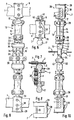
- FIG. 1 and FIG. 11 show a top view and a frontal view of a ring fixator ring 1. It shows the mounting of wire bearings 6, each of which consists of a ring U-holder 7 and a perforated bearing 8 - or, in the case of a structure symmetrical to the plane of the rings 1, of two opposing perforated bearings 8.
- the attachment of the ring U holder 7 on the fixator ring 1 is such that the ring U holder 7, with its open U side facing the ring 1, as in the median-vertical section through the left U- Holder 7 of Figure 11 shown, form-fitting on the ring 1 at a defined from the entire assembly plan or at any place and then locked by inserting a locking connector 28.
- This locking plug shown in Figures 12 and 13 in side view and top view, consists of a support plate 29 and attached in it paired pins 30 which protrude beyond the ring 1 and insert their free ends within the ring U-holder 7. After this plug-in assembly has been carried out, the wire holder 6 is initially freely displaceable on the ring circumference.
- the locking plug 28 does not fall out of the aligned bores of the U-legs of the ring U-holder, since the ends of the pins 30 have slits which can be bent open for the purpose of a sufficiently tight fit of the locking plug 28.
- the perforated bearing 8 consists of a cylindrical part, to which a tapered part, also in a cylindrical shape, is connected, which has an annular groove 27 at its lower end.
- the distance between the ring groove 27 and the bearing shell 40 of the perforated bearing 8 can be different, so that the required height distance of the threaded wires 2 from the associated ring can be selected with a corresponding perforated bearing selection.
- spherical shells 40 can be sunk into the perforated bearings 8 both at the entry point of the threaded wires 2 and at their exit point, which simplifies assembly as the rotatable position of the perforated bearings 8 is advantageous.
- Figures 2 and 3 show in longitudinal section or plan view a wire clamping nut 3 which is screwed onto a threaded wire 2.
- the wire clamping nut 3 has a spherical bearing surface 19, with which it is pivotably mounted in the bearing shell 40 of the perforated bearing 8, as can be seen from FIG. 31.
- the threaded wires 2 can also be inserted and removed from the end face into the bearing shells 40 via the slots 41 of the perforated bearings 8.
- the interaction of the displaceable ring U-holder 7 with the rotatable perforated bearings 8 and the pivotably mounted wire tension nuts 3 results in a spatially largely unlimited adjustability of the threaded wires 2 with regard to their anatomically oriented placement and their penetration direction, which must be carefully selected with regard to vulnerable nerve and vascular structures.
- the wire clamping nuts 3 are internally walled at their outer ends with a threaded section 20 for the attachment of such a diameter limited protective caps 21 provided that they can be immersed in hexagon hollow wrenches which engage the hexagonal surfaces of the wire clamping nuts 3.
- FIGS. 4 and 5 show in longitudinal view or plan view wire position nuts 4 that can be countered against one another on the end face and have longitudinal polyhedron edges on the surface. These can be fixed in a rotationally fixed manner at each location of the threaded wires 2 by mutual locking. They are used for longitudinal wire restraint, the polyhedron edges converging at the end making frictional contact with the bone entry points of the threaded wires 2 and thus holding the same in a non-rotatable position during a wire-tightening screwing operation.
- Figures 7, 8 and 11 represent i.a. shows that the cross-sections of the ring walls can be portrait or square, so that in addition to the preferred horizontal, to be carried out in the ring radius direction of the ring U-holder 7, as is the case with portrait format of the ring wall cross-sections, also rotated by 90 degrees , vertical to the ring level from above or from below, the plug can be selected.
- the square ring wall cross section induces consistent configurations of the ring U-holder with respect to the connection arrangements of attachable perforated bearings 8 and coupling members 17.
- FIGS. 9 and 10 show the preferred designs of the different sections of the struts 9.
- the struts 9 can be pivoted between the rings 1 in the ball bearings 16 by means of the ring U holder 7 and the coupling member 17 and can be mounted in a height-adjustable manner by means of the sleeve bearings 15 and the screw sleeves 22.
- the wall slots 44 shown in FIGS. 10, 15 and 16 make the strut sleeves 13, As shown in longitudinal section in FIG. 14, to tensioning sleeves 14, the tensioning tensioning screws 39, both on the sleeve bearing 15 and on the ball bearing 16, shown in corresponding cross sections of FIGS.
- FIG. 18 shows a longitudinal section of an alternative embodiment of the strut spindles 12.
- the screw sleeve 22 can be dispensed with, since this spindle 12 - hollowed out to save weight - can be inserted into the frame crossbeam 35 with a pin-shaped plug-in end with an annular groove 27 , and in this form the strut spindle 12 can be both rotatably locked and locked in a rotationally fixed manner by means of a grub screw 38.
- the flange 24 and the plug-in holes 26 in turn serve to transmit the screwing forces for the telescopic length adjustment of the struts 9.
- FIGS. 19 to 22 show different views or sections of a transport device for adjusting the height of rod-wire bearings 32 mounted on the strut frame supports 34.
- Cross members 43 hold the transporting spindle 31 on the frame members 34, on which one or more adjusting nuts 33 can be attached.
- These height-adjustable adjusting nuts 33, on which the rod wire bearings 32 are held cause an exactly adjustable displacement of the threaded wires 2.
- tension adjustments of the wires 2 which in turn are relative Can cause displacement of a piece of bone against another adjacent piece of bone.
- wire bearings 32 can be mounted either displaceably or ascertainably without the use of a transport device. In the case of changes in the strut lengths carried out by means of the telescopic strut bearings 13 with displaceably held rod-wire bearings 32, threaded wires 2 which move along maintain their output voltage.
- FIGS. 23-26 show different views and sections of the pluggable, locking, rotating and lockable connection of two frame-shaped strut sections to one another, the design and mode of operation of the coupling axis 37 connecting these strut sections being shown.
- the relative rotatability of two strut sections coupled to one another in this way leads to the possibility of bringing them into positions rotated differently from one another and thus of being able to drill horizontal wires in divergent directions in a bone-transfixing manner at different height levels.
- FIGS. 27 and 28 show that the orthograd-cylindrical mounting forms of the ring fixator are also modified by bending 36 of the coupling members 17 and that additional and increasingly pivotable compositions can thus be realized.
- FIG. 32 shows a ring fixator, which is mounted on the lower leg and consists of two rings 1 and three struts 9, while maintaining the reference numerals previously used, using two transport devices. From this figure, the spatial changeability of all parts to one another can be seen. As well it is obvious from this figure that the ring fixator according to the invention is a kit or a kit that can be changed over a wide range.
- the ring fixator according to the invention can be used in the art of bone surgery disciplines for a large number of tasks. It is used for bone, joint and soft tissue treatment in the inpatient clinic area as well as in the operative or aftercare outpatient area.
- this ring fixator can be used especially for the treatment of broken bones of the limbs, for lengthening the limbs, for healing of false joints, for re-shaping bones in congenital people or acquired bone defects, to correct misalignment of the limbs and large body joints, to heal bone marrow widening, to remobilize stiff joints, as well as for acute treatment in the event of mass accidents and disaster situations, in the latter case the specificity in adaptability to irregular makeshift situations Elimination of inpatient treatment and saving of general anesthesia.
- a special application is the safe help function of this ring fixator in the treatment of mutilating serious injuries, such as those caused by explosions and projectiles.
Landscapes
- Health & Medical Sciences (AREA)
- Orthopedic Medicine & Surgery (AREA)
- Life Sciences & Earth Sciences (AREA)
- Surgery (AREA)
- Biomedical Technology (AREA)
- Engineering & Computer Science (AREA)
- Nuclear Medicine, Radiotherapy & Molecular Imaging (AREA)
- Heart & Thoracic Surgery (AREA)
- Medical Informatics (AREA)
- Molecular Biology (AREA)
- Animal Behavior & Ethology (AREA)
- General Health & Medical Sciences (AREA)
- Public Health (AREA)
- Veterinary Medicine (AREA)
- Surgical Instruments (AREA)
Claims (11)
qu'elle comporte des écrous de positionnement (4) à visser sur les fils filetés (2,5) (suivant la caractéristique 1b) et présentant des surfaces (18) polyédriques à arêtes assurant un blocage sûr à l'épreuve de la torsion sur les fils et un positionnement sur toute une ligne ou toute une surface aux parois de l'os.
qu'elle comporte des écrous tendeurs des fils (3) avec une surface d'appui sphérique (19) et dont l'extrémité est pourvue d'un filet (20) permettant de visser des capots protecteurs (21) sur celle-ci.
qu'elle comporte des douilles filetées (22) pouvant être mises et fixées par rotation sur les extrémités fusiformes (12) des barres (9) (selon la caractéristique 1d) et qui présentent une section filetée (25) et au moins deux fentes longitudinales (23) pour transmettre les forces de serrage des douilles de serrage extérieures aux broches (12) situées à l'intérieur.
que les broches (12) (selon la caractéristique 1d) présentent une bride (24), une section filetée (25), une surface pouvant recevoir une clé et/ou une couronne à trous pour clé (26) sur le pourtour de la bride et une rainure annulaire (27) pour l'engrenage de vis assurant le verrouillage et la protection contre la torsion.
qu'elle présente des fiches de verrouillage (28) en tant que deux pivots (30) fixés perpendiculairement sur une plaque de support (29) et dont les extrémités libres sont fendues.
qu'elle comporte des broches filetées (31) pouvant être fixées sur les barres en disposition parallèle axiale et que sur lesdites broches sont disposés des écrous de réglage (33) dévissables déterminant la hauteur des paliers des fils.
que les barres (9) (selon la caractéristiques 1d) se présentent sous forme d'un cadre comportant deux poutres (34) à axes longitudinaux parallèles et des traverses (35) disposées à angle droit par rapport à ceux-ci pouvant être reliés par des broches (12) échangeables, verrouillables et serrables.
que les organes d'accouplement (17) (selon la caractéristique 1e) sont coudés dans leur axe longitudinal (36).
qu'elle présente des axes d'accouplement (37) pour assembler et tourner en sens inverse des sections de barres (34,35) et qui peuvent être embrochés et tournés ainsi que verrouillés pour l'engrenage de vis (38) et serrés à bloc avec une rainure annulaire (27).
que les anneaux (1) et/ou les parties d'anneaux sont réalisés en fibres continues enroulées unidirectionnellement en sens circonférentiel et noyées dans une matrice, le tout étant doté d'une gaine en matière plastique.
Priority Applications (1)
| Application Number | Priority Date | Filing Date | Title |
|---|---|---|---|
| AT88905179T ATE68680T1 (de) | 1987-06-19 | 1988-06-02 | Ringfixateur zur einrichten, befestigen und regulieren der spannlage von knochenabschnitten. |
Applications Claiming Priority (2)
| Application Number | Priority Date | Filing Date | Title |
|---|---|---|---|
| DE19873720242 DE3720242A1 (de) | 1987-06-19 | 1987-06-19 | Ringfixateur zum einrichten von knochenabschnitten und/oder -fragmenten und zum erzeugen von knochen-spannlagen |
| DE3720242 | 1987-06-19 |
Publications (2)
| Publication Number | Publication Date |
|---|---|
| EP0366678A1 EP0366678A1 (fr) | 1990-05-09 |
| EP0366678B1 true EP0366678B1 (fr) | 1991-10-23 |
Family
ID=6329875
Family Applications (1)
| Application Number | Title | Priority Date | Filing Date |
|---|---|---|---|
| EP88905179A Expired - Lifetime EP0366678B1 (fr) | 1987-06-19 | 1988-06-02 | Fixateur a anneaux d'ajustement, de fixation et de reglage de la position de serrage de sections d'os |
Country Status (7)
| Country | Link |
|---|---|
| US (1) | US5087258A (fr) |
| EP (1) | EP0366678B1 (fr) |
| KR (1) | KR890701063A (fr) |
| AT (1) | ATE68680T1 (fr) |
| AU (1) | AU1935488A (fr) |
| DE (3) | DE3720242A1 (fr) |
| WO (1) | WO1988010099A1 (fr) |
Families Citing this family (64)
| Publication number | Priority date | Publication date | Assignee | Title |
|---|---|---|---|---|
| DE9006716U1 (de) * | 1990-06-15 | 1991-07-25 | Schewior, Thomas, Dr.med., 6903 Neckargemünd | Draht oder Nagel mit Haltemitteln für einen Fixateur |
| DE4119720A1 (de) * | 1990-06-15 | 1991-12-19 | Thomas Dr Med Schewior | Draht oder nagel mit haltemittel, vorzugsweise fuer einen fixateur |
| JPH084020Y2 (ja) * | 1991-04-10 | 1996-02-07 | ユニ・チャーム株式会社 | 使い捨てオムツ |
| DE9108566U1 (de) * | 1991-07-12 | 1991-10-10 | Pennig, Dietmar, Dr.med., 4400 Münster | Klemmkupplung |
| FR2683712B1 (fr) * | 1991-11-18 | 1995-12-29 | Hades | Capuchon de protection d'une broche d'osteosynthese et ensemble comportant ce capuchon ainsi qu'un organe pour sa fixation sur la broche. |
| US5372597A (en) * | 1993-05-12 | 1994-12-13 | Smith & Nephew Richards, Inc. | Supination-pronation device |
| US5437668A (en) * | 1994-02-18 | 1995-08-01 | Board Of Trustees Of The University Of Ark. | Apparatus and method for clinical use of load measurement in distraction osteogenesis |
| USD367531S (en) | 1994-06-27 | 1996-02-27 | Zimmer, Inc. | External fixation clamp |
| US5496319A (en) * | 1994-06-27 | 1996-03-05 | Zimmer, Inc. | External fixation apparatus |
| USD367529S (en) | 1994-06-27 | 1996-02-27 | Zimmer, Inc. | External fixation wire retainer |
| US5578041A (en) * | 1994-10-14 | 1996-11-26 | Trustees Of The University Of Pennsylvania | External fixation device |
| US5591164A (en) * | 1994-12-22 | 1997-01-07 | Zimmer, Inc. | External fixation apparatus and system |
| USD373635S (en) | 1995-11-14 | 1996-09-10 | Zimmer, Inc. | External fixation clamp |
| USD373632S (en) | 1995-11-14 | 1996-09-10 | Zimmer, Inc. | External fixation wire retainer |
| US5797908A (en) * | 1997-02-04 | 1998-08-25 | Bristol-Myers Squibb Company | External fixator assembly and clamp therefor |
| US6056748A (en) * | 1998-02-20 | 2000-05-02 | Weiner; Lon S. | Modular fixator assembly |
| CA2409198C (fr) * | 2000-05-26 | 2008-11-04 | Orthofix S.R.L. | Dispositif de fixation exterieur jetable |
| US7261713B2 (en) | 2001-10-09 | 2007-08-28 | Synthes (Usa) | Adjustable fixator |
| US6746448B2 (en) | 2002-05-30 | 2004-06-08 | Millennium Medical Technologies, Inc. | Outrigger for bone fixator |
| US6652524B1 (en) | 2002-05-30 | 2003-11-25 | Millennium Medical Technologies, Inc. | Fixator with outrigger |
| US7615051B2 (en) * | 2003-02-21 | 2009-11-10 | Synthes Usa, Llc | Craniofacial fracture reduction assembly |
| US6964663B2 (en) * | 2003-09-16 | 2005-11-15 | Ez Concepts Surgical Device Corporation | Combination bone fixation/immobilization apparatus |
| US8029505B2 (en) * | 2005-08-25 | 2011-10-04 | Synthes Usa, Llc | External fixation system and method of use |
| US7422593B2 (en) * | 2005-12-08 | 2008-09-09 | Ebi, L.P. | External fixation system |
| US7749224B2 (en) * | 2005-12-08 | 2010-07-06 | Ebi, Llc | Foot plate fixation |
| US7985221B2 (en) * | 2006-04-20 | 2011-07-26 | Millennium Medical Technologies, Inc. | External fixator |
| AU2007352211B2 (en) * | 2007-04-30 | 2013-05-02 | Ao Technology Ag | Sleeve for a transfixation device for an external skeletal fixator |
| US7806843B2 (en) * | 2007-09-25 | 2010-10-05 | Marin Luis E | External fixator assembly |
| CN100566671C (zh) * | 2007-11-29 | 2009-12-09 | 李昭中 | 骨折对位机 |
| EP2085037B1 (fr) * | 2008-02-01 | 2013-07-24 | Stryker Trauma SA | Jambe de force télescopique pour fixateur externe |
| US8114077B2 (en) | 2008-02-01 | 2012-02-14 | Stryker Trauma Sa | Clamping pin |
| EP2085038B1 (fr) * | 2008-02-01 | 2011-11-30 | Stryker Trauma SA | Joint sphérique pour fixateur externe |
| EP2110090A1 (fr) * | 2008-04-18 | 2009-10-21 | Stryker Trauma SA | Plaque de fixation orthopédique perméable aux rayons X |
| EP2110089A1 (fr) | 2008-04-18 | 2009-10-21 | Stryker Trauma SA | Plaque de fixation orthopédique |
| US20100179548A1 (en) * | 2009-01-13 | 2010-07-15 | Marin Luis E | External fixator assembly |
| EP2405834B1 (fr) * | 2009-03-10 | 2016-07-20 | Stryker European Holdings I, LLC | Fixateur externe |
| US8858555B2 (en) | 2009-10-05 | 2014-10-14 | Stryker Trauma Sa | Dynamic external fixator and methods for use |
| GB201008281D0 (en) | 2010-05-19 | 2010-06-30 | Nikonovas Arkadijus | Indirect analysis and manipulation of objects |
| US8870799B2 (en) * | 2010-05-28 | 2014-10-28 | Fixes 4 Kids Inc. | Systems, devices, and methods for mechanically reducing and fixing bone fractures |
| US11141196B2 (en) | 2010-08-11 | 2021-10-12 | Stryker European Operations Holdings Llc | External fixator system |
| EP2417924B1 (fr) | 2010-08-11 | 2015-07-01 | Stryker Trauma SA | Système de fixateur externe |
| US8945128B2 (en) | 2010-08-11 | 2015-02-03 | Stryker Trauma Sa | External fixator system |
| US9265529B2 (en) * | 2010-11-30 | 2016-02-23 | Nikolaj Wolfson | Orthopedic fixation systems and methods |
| US8906021B1 (en) * | 2012-08-20 | 2014-12-09 | Stryker Trauma Sa | Telescopic strut for an external fixator |
| US9101398B2 (en) | 2012-08-23 | 2015-08-11 | Stryker Trauma Sa | Bone transport external fixation frame |
| US9039706B2 (en) | 2013-03-13 | 2015-05-26 | DePuy Synthes Products, Inc. | External bone fixation device |
| US9675382B2 (en) * | 2013-03-13 | 2017-06-13 | DePuy Synthes Products, Inc. | External bone fixation device |
| US10463522B2 (en) | 2013-03-14 | 2019-11-05 | Mdpo Llc | Dynamic foot plate |
| US10980655B1 (en) | 2013-03-14 | 2021-04-20 | Mdpo Llc | Dynamic foot plate |
| US10993868B2 (en) | 2013-03-14 | 2021-05-04 | Mdpo Llc | Dynamic foot plate |
| US9827011B2 (en) * | 2013-03-15 | 2017-11-28 | Biomet Manufacturing, Llc | Polyaxial pivot housing for external fixation system |
| US9936975B2 (en) | 2014-09-09 | 2018-04-10 | Integra Lifesciences Corporation | External fixation system |
| CN106388919B (zh) * | 2014-10-24 | 2019-03-12 | 毕宝亮 | 可实现微创手术目的的圈簧形骨外固定器及其工作方法 |
| US11141198B2 (en) * | 2015-04-15 | 2021-10-12 | Umc Utrecht Holding B.V. | Coupling device for in an orthopaedic system |
| US10010350B2 (en) | 2016-06-14 | 2018-07-03 | Stryker European Holdings I, Llc | Gear mechanisms for fixation frame struts |
| CN105919659A (zh) * | 2016-06-27 | 2016-09-07 | 重庆富沃思医疗器械有限公司 | 一种用于可调式固定支具的盆骨固定套组件 |
| US10835318B2 (en) | 2016-08-25 | 2020-11-17 | DePuy Synthes Products, Inc. | Orthopedic fixation control and manipulation |
| US10874433B2 (en) | 2017-01-30 | 2020-12-29 | Stryker European Holdings I, Llc | Strut attachments for external fixation frame |
| US11883074B2 (en) * | 2018-09-07 | 2024-01-30 | Orthex, LLC | Hole transporter |
| EP3860481A4 (fr) | 2018-10-04 | 2022-05-18 | University of Utah Research Foundation | Fixateur torsionnel couplé et procédé d'utilisation |
| US12274475B2 (en) | 2018-10-04 | 2025-04-15 | Peter M. Stevens | Automated coupled torsional fixators and method of use |
| US11439436B2 (en) | 2019-03-18 | 2022-09-13 | Synthes Gmbh | Orthopedic fixation strut swapping |
| US11304757B2 (en) | 2019-03-28 | 2022-04-19 | Synthes Gmbh | Orthopedic fixation control and visualization |
| US11334997B2 (en) | 2020-04-03 | 2022-05-17 | Synthes Gmbh | Hinge detection for orthopedic fixation |
Citations (1)
| Publication number | Priority date | Publication date | Assignee | Title |
|---|---|---|---|---|
| EP0194187A1 (fr) * | 1985-02-22 | 1986-09-10 | Jean-Marie Hardy | Dispositif de fixateur externe à usage orthopédique |
Family Cites Families (11)
| Publication number | Priority date | Publication date | Assignee | Title |
|---|---|---|---|---|
| SU538710A1 (ru) * | 1974-04-12 | 1976-12-15 | Курганский Научно-Исследовательский Институт Экспериментальной И Клинической Ортопедии И Травмотологии | Компрессионно-дистракционный аппарат г.а.илизарова |
| DE2745504A1 (de) * | 1977-10-10 | 1979-04-19 | Erich Strickle | Vorrichtung zur ruhigstellung oder stuetzung von gliedmassen von menschen und tieren |
| DE2832631A1 (de) * | 1978-07-25 | 1980-02-07 | Tsnii Travmatologii I Ortopedi | Apparat zur beweglichmachung des hueftgelenks |
| DE3244819A1 (de) * | 1982-12-03 | 1984-06-07 | Ortopedia Gmbh, 2300 Kiel | Vorrichtung zur externen fixierung von knochenfragmenten |
| CU21459A1 (en) * | 1983-02-02 | 1987-01-13 | Mini Salud Publ | Fix external orthopedic apparatus |
| EP0146872A3 (fr) * | 1983-12-17 | 1986-10-29 | Schewior, Thomas, Dr.med. | Appareil pour ostéosynthèse |
| ATE48234T1 (de) * | 1984-02-08 | 1989-12-15 | Zausmed Inc | Knochenwachstumsstimulator. |
| US4584995A (en) * | 1984-04-26 | 1986-04-29 | Orthotic Limited Partnership | External fixation device |
| CH664079A5 (fr) * | 1985-01-24 | 1988-02-15 | Jaquet Orthopedie | Element d'arceau et fixateur externe pour osteosynthese et osteoplastie. |
| DE3510305A1 (de) * | 1985-03-22 | 1986-09-25 | Isidor Prof. Dr.med. 6930 Eberbach Wasserstein | Vorrichtung zur externen fixation von knochensegmenten |
| AT384360B (de) * | 1985-09-18 | 1987-11-10 | Kurgansky Niiex I Klinicheskoi | Antrieb fuer kompressions-distraktionsapparate |
-
1987
- 1987-06-19 DE DE19873720242 patent/DE3720242A1/de not_active Withdrawn
-
1988
- 1988-06-02 AU AU19354/88A patent/AU1935488A/en not_active Abandoned
- 1988-06-02 AT AT88905179T patent/ATE68680T1/de active
- 1988-06-02 DE DE8888905179T patent/DE3865842D1/de not_active Expired - Lifetime
- 1988-06-02 EP EP88905179A patent/EP0366678B1/fr not_active Expired - Lifetime
- 1988-06-02 DE DE88DE8800323T patent/DE3890496D2/de not_active Expired
- 1988-06-02 WO PCT/DE1988/000323 patent/WO1988010099A1/fr not_active Ceased
- 1988-06-02 KR KR1019890700316A patent/KR890701063A/ko not_active Withdrawn
- 1988-06-04 US US07/457,745 patent/US5087258A/en not_active Expired - Fee Related
Patent Citations (1)
| Publication number | Priority date | Publication date | Assignee | Title |
|---|---|---|---|---|
| EP0194187A1 (fr) * | 1985-02-22 | 1986-09-10 | Jean-Marie Hardy | Dispositif de fixateur externe à usage orthopédique |
Also Published As
| Publication number | Publication date |
|---|---|
| DE3720242A1 (de) | 1988-12-29 |
| US5087258A (en) | 1992-02-11 |
| DE3890496D2 (en) | 1989-05-24 |
| AU1935488A (en) | 1989-01-19 |
| ATE68680T1 (de) | 1991-11-15 |
| KR890701063A (ko) | 1989-12-19 |
| DE3865842D1 (de) | 1991-11-28 |
| WO1988010099A1 (fr) | 1988-12-29 |
| EP0366678A1 (fr) | 1990-05-09 |
Similar Documents
| Publication | Publication Date | Title |
|---|---|---|
| EP0366678B1 (fr) | Fixateur a anneaux d'ajustement, de fixation et de reglage de la position de serrage de sections d'os | |
| DE3000432C2 (fr) | ||
| DE69433433T2 (de) | Befestigungsvorrichtung für lange Knochen | |
| DE3244819C2 (fr) | ||
| EP0671151B1 (fr) | Dispositif d'ostéosynthèse | |
| DE60007256T2 (de) | Querverbindung für die Wirbelsäule | |
| EP0553782B1 (fr) | Implant rachidien et instrument de reposition | |
| DE3936702C2 (de) | Pedikelschraube und Korrektur- und Haltevorrichtung mit einer solchen Pedikelschraube | |
| DE3823737C2 (fr) | ||
| DE3639810C2 (de) | Implantat zur Wirbelsäulenkorrektur und/oder -stabilisierung | |
| DE60034489T2 (de) | Vorrichtung zur externen transpedikularen wirbelsäulenfixierung | |
| EP0153546B1 (fr) | Fixation pour immobiliser des fragments d'os | |
| DE69331525T2 (de) | Wirbelsäulenosteosyntese-instrumentarium für eine behandlung von vorn | |
| EP0328883B1 (fr) | Dispositif d'étaiement de la colonne vertébrale humaine | |
| DE19750493A1 (de) | Implantat zur Stabilisierung einer Fraktur und Schraube zur Verwendung in der Chirurgie | |
| EP0314021A2 (fr) | Dispositif pour fixer des parties d'os | |
| DE3614305A1 (de) | Aeusserlich anwendbarer fixateur | |
| DE3807335C2 (fr) | ||
| EP0146872A2 (fr) | Appareil pour ostéosynthèse | |
| DE10328307A1 (de) | Wirbelkörperprothese | |
| DE2946784A1 (de) | Vorrichtung zum festlegen von gebrochenen knochen | |
| EP0443388B1 (fr) | Eclisse de fixation et de mobilisation | |
| DE3539616A1 (de) | Fixateur externe | |
| DE102018007224B4 (de) | Vorrichtung zum Verbinden von Objekten, insbesondere zum vorzugsweise extrakorporalen Verbinden von Knochenfragmenten am Körper während eines Heilungsprozesses | |
| DE10226496A1 (de) | Wirbelplatte |
Legal Events
| Date | Code | Title | Description |
|---|---|---|---|
| PUAI | Public reference made under article 153(3) epc to a published international application that has entered the european phase |
Free format text: ORIGINAL CODE: 0009012 |
|
| 17P | Request for examination filed |
Effective date: 19891218 |
|
| AK | Designated contracting states |
Kind code of ref document: A1 Designated state(s): AT BE CH DE FR GB IT LI LU NL SE |
|
| 17Q | First examination report despatched |
Effective date: 19900830 |
|
| GRAA | (expected) grant |
Free format text: ORIGINAL CODE: 0009210 |
|
| AK | Designated contracting states |
Kind code of ref document: B1 Designated state(s): AT BE CH DE FR GB IT LI LU NL SE |
|
| PG25 | Lapsed in a contracting state [announced via postgrant information from national office to epo] |
Ref country code: SE Effective date: 19911023 Ref country code: NL Effective date: 19911023 |
|
| REF | Corresponds to: |
Ref document number: 68680 Country of ref document: AT Date of ref document: 19911115 Kind code of ref document: T |
|
| REF | Corresponds to: |
Ref document number: 3865842 Country of ref document: DE Date of ref document: 19911128 |
|
| ITF | It: translation for a ep patent filed | ||
| ET | Fr: translation filed | ||
| PGFP | Annual fee paid to national office [announced via postgrant information from national office to epo] |
Ref country code: FR Payment date: 19920224 Year of fee payment: 5 |
|
| PGFP | Annual fee paid to national office [announced via postgrant information from national office to epo] |
Ref country code: BE Payment date: 19920225 Year of fee payment: 5 |
|
| GBT | Gb: translation of ep patent filed (gb section 77(6)(a)/1977) | ||
| NLV1 | Nl: lapsed or annulled due to failure to fulfill the requirements of art. 29p and 29m of the patents act | ||
| PGFP | Annual fee paid to national office [announced via postgrant information from national office to epo] |
Ref country code: GB Payment date: 19920410 Year of fee payment: 5 |
|
| PGFP | Annual fee paid to national office [announced via postgrant information from national office to epo] |
Ref country code: LU Payment date: 19920415 Year of fee payment: 5 |
|
| PGFP | Annual fee paid to national office [announced via postgrant information from national office to epo] |
Ref country code: CH Payment date: 19920827 Year of fee payment: 5 |
|
| PLBE | No opposition filed within time limit |
Free format text: ORIGINAL CODE: 0009261 |
|
| STAA | Information on the status of an ep patent application or granted ep patent |
Free format text: STATUS: NO OPPOSITION FILED WITHIN TIME LIMIT |
|
| 26N | No opposition filed | ||
| EPTA | Lu: last paid annual fee | ||
| PGFP | Annual fee paid to national office [announced via postgrant information from national office to epo] |
Ref country code: DE Payment date: 19930419 Year of fee payment: 6 |
|
| PGFP | Annual fee paid to national office [announced via postgrant information from national office to epo] |
Ref country code: AT Payment date: 19930525 Year of fee payment: 6 |
|
| PG25 | Lapsed in a contracting state [announced via postgrant information from national office to epo] |
Ref country code: LU Free format text: LAPSE BECAUSE OF NON-PAYMENT OF DUE FEES Effective date: 19930602 Ref country code: GB Effective date: 19930602 |
|
| PG25 | Lapsed in a contracting state [announced via postgrant information from national office to epo] |
Ref country code: LI Effective date: 19930630 Ref country code: CH Effective date: 19930630 Ref country code: BE Effective date: 19930630 |
|
| BERE | Be: lapsed |
Owner name: SCHEWIOR THOMAS Effective date: 19930630 |
|
| GBPC | Gb: european patent ceased through non-payment of renewal fee |
Effective date: 19930602 |
|
| PG25 | Lapsed in a contracting state [announced via postgrant information from national office to epo] |
Ref country code: FR Effective date: 19940228 |
|
| REG | Reference to a national code |
Ref country code: CH Ref legal event code: PL |
|
| REG | Reference to a national code |
Ref country code: FR Ref legal event code: ST |
|
| PG25 | Lapsed in a contracting state [announced via postgrant information from national office to epo] |
Ref country code: AT Effective date: 19940602 |
|
| PG25 | Lapsed in a contracting state [announced via postgrant information from national office to epo] |
Ref country code: DE Effective date: 19950401 |
|
| PG25 | Lapsed in a contracting state [announced via postgrant information from national office to epo] |
Ref country code: IT Free format text: LAPSE BECAUSE OF NON-PAYMENT OF DUE FEES;WARNING: LAPSES OF ITALIAN PATENTS WITH EFFECTIVE DATE BEFORE 2007 MAY HAVE OCCURRED AT ANY TIME BEFORE 2007. THE CORRECT EFFECTIVE DATE MAY BE DIFFERENT FROM THE ONE RECORDED. Effective date: 20050602 |