EP0366745B1 - Appareil d'impression - Google Patents
Appareil d'impression Download PDFInfo
- Publication number
- EP0366745B1 EP0366745B1 EP89904423A EP89904423A EP0366745B1 EP 0366745 B1 EP0366745 B1 EP 0366745B1 EP 89904423 A EP89904423 A EP 89904423A EP 89904423 A EP89904423 A EP 89904423A EP 0366745 B1 EP0366745 B1 EP 0366745B1
- Authority
- EP
- European Patent Office
- Prior art keywords
- print head
- carriage
- printing apparatus
- heat transfer
- transfer means
- Prior art date
- Legal status (The legal status is an assumption and is not a legal conclusion. Google has not performed a legal analysis and makes no representation as to the accuracy of the status listed.)
- Expired
Links
- 238000010276 construction Methods 0.000 claims description 5
- 239000011159 matrix material Substances 0.000 abstract description 4
- 238000009434 installation Methods 0.000 description 2
- 238000012423 maintenance Methods 0.000 description 2
- XAGFODPZIPBFFR-UHFFFAOYSA-N aluminium Chemical compound [Al] XAGFODPZIPBFFR-UHFFFAOYSA-N 0.000 description 1
- 229910052782 aluminium Inorganic materials 0.000 description 1
- 238000012986 modification Methods 0.000 description 1
- 230000004048 modification Effects 0.000 description 1
Images

Classifications
-
- B—PERFORMING OPERATIONS; TRANSPORTING
- B41—PRINTING; LINING MACHINES; TYPEWRITERS; STAMPS
- B41J—TYPEWRITERS; SELECTIVE PRINTING MECHANISMS, i.e. MECHANISMS PRINTING OTHERWISE THAN FROM A FORME; CORRECTION OF TYPOGRAPHICAL ERRORS
- B41J29/00—Details of, or accessories for, typewriters or selective printing mechanisms not otherwise provided for
- B41J29/377—Cooling or ventilating arrangements
Definitions
- the present invention relates to a printing apparatus and more particularly, but not exclusively, to a dot matrix printing apparatus having heat transfer means associated with the print head for transferring heat therefrom.
- a dot matrix printer having a print head of circular configuration and of multiple element type operates its print head at high speed and with a large electrical loading. There is therefore a requirement for transferring heat by conduction and convection away from the print head during its operation. This may be accomplished by providing a heat sink within the print head itself and by employing additional heat transfer means, such as a plurality of fins, external to and surrounding a portion of the print head.
- additional heat transfer means such as a plurality of fins
- One of the drawbacks of the above-mentioned prior art arrangement is that the servicing time for a print head, as well as the initial installation time and time for replacing a print head, is substantially increased by the extra work involved in assembling the fins around the print head. The extra work increases installation time and the period during which the printer is inoperative during a maintenance operation.
- the present invention provides a printing apparatus including a carriage for carrying a print head and heat transfer means operably associated with said print head for transferring heat therefrom, characterized in that said carriage includes pivot means coupled with said heat transfer means for allowing swinging thereof from a first position covering said print head to a second position uncovering said print head to permit removal thereof from said carriage, and securing means coupled to said carriage and to said heat transfer means for retaining said heat transfer means in said first position.
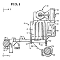
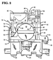
- Figs. l and 2 illustrate a side elevational view and a front elevational view, respectively, of the print head assembly in accordance with one embodiment of the invention.
- a pair of guide rails or shafts 20 and 22 carry a carriage 24 in transverse manner across a printer 26 of the type, as shown in Fig. 3.
- the printer 26 includes a journal station 28, a receipt station 30, and a slip station 32.
- the journal station 28 is positioned on the right hand side of the printer 26 and the receipt station 30 and the slip station 32 occupy the left hand side of the printer 26.
- the carriage 24 is of unitary construction and includes a pair of spaced bearings 34 and 36 at the rear part of the carriage 24.
- the carriage 24 has a single bearing 38 of U-shaped construction at the front part. The details of the carriage 24 are more fully described in a co-pending PCT application, entitled “Printing Apparatus” and claiming priority from U.S. application l76,957 and assigned to the same assignee as the present application.
- a print head 40 of the dot matrix type in a circular configuration (Fig. 2) is mounted on the carriage 24.
- the print head 40 includes a plurality of print wires (not shown) which are moved in back and forth manner by a plurality of actuating coils (also not shown) in printing operation.
- the print head 40 operates in a compact environment and generates an amount of heat that must be transferred or transmitted away from the print head 40 for efficient operation.
- the means for transferring or dissipating heat from the print head 40 is effected with a heat sink, generally indicated by reference numeral 42.
- the die cast aluminum heat sink 42 generally covers and surrounds the actuating or rear portion 44 of the print head 40.
- the heat sink 42 includes a top plate portion 46, a right hand plate portion 48, and a left hand plate portion 50.
- the heat sink 42 is of unitary construction and includes ribs 52 on the exterior of plate portion 48 and ribs 54 on the exterior of plate portion 50.
- the heat sink 42 also includes ribs 56 formed in an arcuate arrangement which bridges the side plate portion 48 and the top plate portion 46. Ribs 58 are formed in an arcuate arrangement and bridge the side plate portion 50 and the top plate portion 46.
- the top plate portion 46 extends to the right of Fig. l and covers the nose portion 60 of the print head 40.
- the heat sink 42 includes a pair of doglegs 62 and 64 at the right hand side thereof.
- a pivot pin 66 is secured to the doglegs 62, 64 to provide for swinging movement of the heat sink 42.
- the carriage 24 has a bearing 68 as an integral part at the right hand side thereof and of a length occupying the space between the doglegs 62 and 64.
- the bearing 68 and the pivot pin 66 provide means for swinging the heat sink 42 from a position covering the print head 40 to a position wherein the print head is uncovered for the purpose of servicing the print head or for removal thereof.
- a latch or clamp 70 is provided at the left hand side of the heat sink 42 to maintain the heat sink in position during printing operation.
- the carriage 24 has a pair of spaced bearings 72 as an integral part at the left hand side thereof, and the latch or clamp 70 is formed in wire bail manner and has ends 74 journaled in the bearings 72.
- the latch or clamp 70 is formed with a curved portion 76 to fit over a ledge 78 of the heat sink 42.
- the wire bail construction of the latch 70 provides for maintaining the heat sink 42 in a secure position by reason that as the heat sink 42 is started to be raised by an operator or other person from the operational mode position, the latch exerts an increased force on the ledge 78 to retain the parts in position.
- the knife mechanism 80 includes a solenoid 82 coupled with a crank arm 84 that is journaled at pivot 86.
- a bifurcated arm 88 as an integral part of the crank arm 84, supports a knife blade 90 which is movable to a cutting position for severing the receipt paper.
- a detailed description of the knife mechanism is found in Shipos et al. U.S. Pat. No. 4,525,088.
- a modification of the print head assembly includes the carriage 24, the print head 40, and the heat sink 42.
- Fig. 3 illustrates the print head 40 and the swingable heat sink 42 but does not show the knife mechanism.
- a print head assembly that includes a swingable heat dissipating element.
Landscapes
- Accessory Devices And Overall Control Thereof (AREA)
- Common Mechanisms (AREA)
- Impact Printers (AREA)
- Electronic Switches (AREA)
Abstract
Claims (7)
- Appareil d'impression comprenant un chariot (24) destiné à porter une tête d'impression (40) et un moyen (42) de transfert de chaleur associé fonctionnellement à ladite tête d'impression (40) pour en transférer de la chaleur, caractérisé en ce que ledit chariot (24) comprend des moyens de pivot (66, 68) couplés audit moyen (42) de transfert de chaleur afin d'en permettre un basculement depuis une première position couvrant ladite tête d'impression (40) jusqu'à une seconde position découvrant ladite tête d'impression (40) pour qu'elle puisse être enlevée dudit chariot (24), et des moyens de fixation (70, 78) couplés audit chariot (24) et audit moyen (42) de transfert de chaleur afin de retenir ledit moyen (42) de transfert de chaleur dans ladite première position.
- Appareil d'impression selon la revendication 1, caractérisé par un mécanisme à couteau (80) fixé audit moyen (42) de transfert de chaleur.
- Appareil d'impression selon la revendication 1 ou la revendication 2, caractérisé en ce que ledit moyen (42) de transfert de chaleur comprend un dissipateur (42) de chaleur définissant des nervures (56, 58) sur chaque côté de ladite tête d'impression (40).
- Appareil d'impression selon l'une quelconque des revendications 1 à 3, caractérisé en ce que lesdits moyens de pivot (66, 68) comprennent un axe allongé (66) tourillonnant dans un palier (68).
- Appareil d'impression selon l'une quelconque des revendications 1 à 4, caractérisé en ce que lesdits moyens de fixation (70, 78) comprennent une bride (70) à ressort montée de façon pivotante sur ledit chariot (24) et pouvant être enclenchée avec ledit moyen (42) de transfert de chaleur sur le côté opposé auxdits moyens de pivot (66, 68).
- Appareil d'impression selon l'une quelconque des revendications 1 à 5, caractérisé en ce que ledit moyen (42) de transfert de chaleur comprend un élément réalisé d'une seule pièce et définit des parties de plaques (46, 48, 50) avec des nervures (56, 58) de forme incurvée adjacentes à ladite tête d'impression (40).
- Appareil d'impression selon la revendication 6, caractérisé en ce que lesdites parties de plaques (46, 48, 50) comprennent une partie de plaque supérieure (46) et des parties de plaques latérales (48, 50), lesdites nervures (56, 58) s'étendant entre ladite partie de plaque supérieure (46) et lesdites parties de plaques latérales (48, 50).
Applications Claiming Priority (2)
| Application Number | Priority Date | Filing Date | Title |
|---|---|---|---|
| US07/176,956 US4867590A (en) | 1988-04-04 | 1988-04-04 | Dot matrix print head carriage with swingable heat sink |
| US176956 | 1988-04-04 |
Publications (2)
| Publication Number | Publication Date |
|---|---|
| EP0366745A1 EP0366745A1 (fr) | 1990-05-09 |
| EP0366745B1 true EP0366745B1 (fr) | 1992-09-23 |
Family
ID=22646590
Family Applications (1)
| Application Number | Title | Priority Date | Filing Date |
|---|---|---|---|
| EP89904423A Expired EP0366745B1 (fr) | 1988-04-04 | 1989-03-24 | Appareil d'impression |
Country Status (4)
| Country | Link |
|---|---|
| US (1) | US4867590A (fr) |
| EP (1) | EP0366745B1 (fr) |
| JP (1) | JP2874775B2 (fr) |
| WO (1) | WO1989009695A1 (fr) |
Families Citing this family (3)
| Publication number | Priority date | Publication date | Assignee | Title |
|---|---|---|---|---|
| JP3372701B2 (ja) * | 1994-05-30 | 2003-02-04 | キヤノン株式会社 | インクジェット記録装置 |
| US7699615B2 (en) * | 2005-02-03 | 2010-04-20 | Christopher Sakezles | Joint replica models and methods of using same for testing medical devices |
| CN118322725A (zh) * | 2024-04-29 | 2024-07-12 | 宁波精芯科技有限公司 | 热敏打印机机芯及热敏打印机 |
Family Cites Families (15)
| Publication number | Priority date | Publication date | Assignee | Title |
|---|---|---|---|---|
| US4064984A (en) * | 1976-10-12 | 1977-12-27 | Toeppen Thurston H | Fastening device for print head |
| US4134695A (en) * | 1977-07-13 | 1979-01-16 | Teletype Corporation | Printer carriage |
| FR2413976A1 (fr) * | 1978-01-05 | 1979-08-03 | Triumph Werke Nuernberg Ag | Fixation d'une tete imprimante a aiguilles sur son support |
| US4229114A (en) * | 1979-02-12 | 1980-10-21 | Dataproducts Corporation | Mechanism for operator-replaceable printhead |
| JPS56109484A (en) * | 1980-02-05 | 1981-08-29 | Matsushita Electric Industrial Co Ltd | Sheathed heater |
| JPS6316526Y2 (fr) * | 1980-08-14 | 1988-05-11 | ||
| US4469454A (en) * | 1980-11-04 | 1984-09-04 | Wang Laboratories, Inc. | Print wheel mounting arrangement for print head and ribbon cartridge assembly |
| JPS57148671A (en) * | 1981-03-09 | 1982-09-14 | Brother Ind Ltd | Paper feeder for printer |
| US4473312A (en) * | 1982-12-06 | 1984-09-25 | Ncr Corporation | Fastening mechanism for removably fastening together two workpieces |
| JPS59224380A (ja) * | 1983-06-03 | 1984-12-17 | Tokyo Electric Co Ltd | プリンタの印字ヘツド保持装置 |
| US4514100A (en) * | 1983-08-19 | 1985-04-30 | At&T Teletype Corporation | Mounting apparatus for dot matrix print head |
| US4525088A (en) * | 1983-08-22 | 1985-06-25 | Ncr Corporation | Compact rotary knife mechanism |
| JPS60183166A (ja) * | 1984-03-01 | 1985-09-18 | Canon Inc | ワイヤ−ドツトヘツド |
| JPS61217259A (ja) * | 1985-03-23 | 1986-09-26 | Canon Inc | ワイヤドツトヘツド |
| JPH0632968B2 (ja) * | 1985-03-26 | 1994-05-02 | セイコーエプソン株式会社 | 印字ヘツド取り付け機構 |
-
1988
- 1988-04-04 US US07/176,956 patent/US4867590A/en not_active Expired - Fee Related
-
1989
- 1989-03-24 EP EP89904423A patent/EP0366745B1/fr not_active Expired
- 1989-03-24 JP JP1504336A patent/JP2874775B2/ja not_active Expired - Lifetime
- 1989-03-24 WO PCT/US1989/001253 patent/WO1989009695A1/fr not_active Ceased
Also Published As
| Publication number | Publication date |
|---|---|
| US4867590A (en) | 1989-09-19 |
| WO1989009695A1 (fr) | 1989-10-19 |
| EP0366745A1 (fr) | 1990-05-09 |
| JPH02503778A (ja) | 1990-11-08 |
| JP2874775B2 (ja) | 1999-03-24 |
Similar Documents
| Publication | Publication Date | Title |
|---|---|---|
| CA1233426A (fr) | Cartouche de ruban encreur multicolore et mecanisme de positionnement connexe pour imprimante serie a impact | |
| EP0990530B1 (fr) | Dispositif de coupe et imprimante le comprenant | |
| EP0806297A2 (fr) | Appareil de formation d'images | |
| HK80989A (en) | An assembly in which a print head is releasably mounted on a carriage | |
| WO1989009695A1 (fr) | Appareil d'impression | |
| JPS6056581A (ja) | キヤリジにドツトマトリクスプリントヘツドを着脱自在に取付ける装置 | |
| US4324496A (en) | Type disc printer | |
| JPS6237743Y2 (fr) | ||
| DE68902976T2 (de) | Druckgeraet. | |
| US5726521A (en) | Electromechanical actuator used in wire-dot printing head | |
| JPH11208041A (ja) | カッタ装置及びこれを用いたプリンタ | |
| JP2000158737A (ja) | ドットラインプリンタ | |
| JPH0250868A (ja) | プリンタ装置 | |
| JPH044157B2 (fr) | ||
| JP4632524B2 (ja) | 印刷装置 | |
| JPH0211432B2 (fr) | ||
| FR2442136A1 (fr) | Tete d'impression pour imprimante a matrice de points | |
| JP2708020B2 (ja) | リボンカセット着脱機構 | |
| JPH0131494Y2 (fr) | ||
| JPH09314966A (ja) | リボンカセット装置 | |
| JPS6040289A (ja) | 印字装置 | |
| JP2772565B2 (ja) | プリント装置 | |
| JP2000052615A (ja) | ドットプリンタのペーパガイド脱着機構 | |
| JPS6339073Y2 (fr) | ||
| KR860001436Y1 (ko) | 타자기의 캐리지 높이 조절 장치 |
Legal Events
| Date | Code | Title | Description |
|---|---|---|---|
| PUAI | Public reference made under article 153(3) epc to a published international application that has entered the european phase |
Free format text: ORIGINAL CODE: 0009012 |
|
| AK | Designated contracting states |
Kind code of ref document: A1 Designated state(s): CH DE FR GB LI |
|
| 17P | Request for examination filed |
Effective date: 19900419 |
|
| 17Q | First examination report despatched |
Effective date: 19920204 |
|
| RAP1 | Party data changed (applicant data changed or rights of an application transferred) |
Owner name: NCR INTERNATIONAL INC. |
|
| GRAA | (expected) grant |
Free format text: ORIGINAL CODE: 0009210 |
|
| AK | Designated contracting states |
Kind code of ref document: B1 Designated state(s): CH DE FR GB LI |
|
| REF | Corresponds to: |
Ref document number: 68902976 Country of ref document: DE Date of ref document: 19921029 |
|
| ET | Fr: translation filed | ||
| PLBE | No opposition filed within time limit |
Free format text: ORIGINAL CODE: 0009261 |
|
| STAA | Information on the status of an ep patent application or granted ep patent |
Free format text: STATUS: NO OPPOSITION FILED WITHIN TIME LIMIT |
|
| 26N | No opposition filed | ||
| PGFP | Annual fee paid to national office [announced via postgrant information from national office to epo] |
Ref country code: FR Payment date: 19990112 Year of fee payment: 11 |
|
| PGFP | Annual fee paid to national office [announced via postgrant information from national office to epo] |
Ref country code: CH Payment date: 19990209 Year of fee payment: 11 |
|
| PGFP | Annual fee paid to national office [announced via postgrant information from national office to epo] |
Ref country code: GB Payment date: 19990226 Year of fee payment: 11 |
|
| PGFP | Annual fee paid to national office [announced via postgrant information from national office to epo] |
Ref country code: DE Payment date: 19990323 Year of fee payment: 11 |
|
| PG25 | Lapsed in a contracting state [announced via postgrant information from national office to epo] |
Ref country code: GB Free format text: LAPSE BECAUSE OF NON-PAYMENT OF DUE FEES Effective date: 20000324 |
|
| PG25 | Lapsed in a contracting state [announced via postgrant information from national office to epo] |
Ref country code: LI Free format text: LAPSE BECAUSE OF NON-PAYMENT OF DUE FEES Effective date: 20000331 Ref country code: CH Free format text: LAPSE BECAUSE OF NON-PAYMENT OF DUE FEES Effective date: 20000331 |
|
| GBPC | Gb: european patent ceased through non-payment of renewal fee |
Effective date: 20000324 |
|
| REG | Reference to a national code |
Ref country code: CH Ref legal event code: PL |
|
| PG25 | Lapsed in a contracting state [announced via postgrant information from national office to epo] |
Ref country code: FR Free format text: LAPSE BECAUSE OF NON-PAYMENT OF DUE FEES Effective date: 20001130 |
|
| REG | Reference to a national code |
Ref country code: FR Ref legal event code: ST |
|
| PG25 | Lapsed in a contracting state [announced via postgrant information from national office to epo] |
Ref country code: DE Free format text: LAPSE BECAUSE OF NON-PAYMENT OF DUE FEES Effective date: 20010103 |