EP0366801A1 - Drahtabrollstruktur für drahtschneidefunkerosionbearbeitungsmaschine - Google Patents
Drahtabrollstruktur für drahtschneidefunkerosionbearbeitungsmaschine Download PDFInfo
- Publication number
- EP0366801A1 EP0366801A1 EP89902297A EP89902297A EP0366801A1 EP 0366801 A1 EP0366801 A1 EP 0366801A1 EP 89902297 A EP89902297 A EP 89902297A EP 89902297 A EP89902297 A EP 89902297A EP 0366801 A1 EP0366801 A1 EP 0366801A1
- Authority
- EP
- European Patent Office
- Prior art keywords
- wire
- discharge
- belts
- electric discharge
- feed roller
- Prior art date
- Legal status (The legal status is an assumption and is not a legal conclusion. Google has not performed a legal analysis and makes no representation as to the accuracy of the status listed.)
- Withdrawn
Links
- 239000000463 material Substances 0.000 claims abstract description 7
- 238000000034 method Methods 0.000 claims description 23
- 239000000919 ceramic Substances 0.000 claims description 5
- 239000007788 liquid Substances 0.000 description 16
- 238000011084 recovery Methods 0.000 description 5
- 238000004804 winding Methods 0.000 description 2
- 238000005452 bending Methods 0.000 description 1
- 239000012153 distilled water Substances 0.000 description 1
- 238000003780 insertion Methods 0.000 description 1
- 230000037431 insertion Effects 0.000 description 1
- 239000007921 spray Substances 0.000 description 1
- XLYOFNOQVPJJNP-UHFFFAOYSA-N water Chemical compound O XLYOFNOQVPJJNP-UHFFFAOYSA-N 0.000 description 1
Images

Classifications
-
- B—PERFORMING OPERATIONS; TRANSPORTING
- B23—MACHINE TOOLS; METAL-WORKING NOT OTHERWISE PROVIDED FOR
- B23H—WORKING OF METAL BY THE ACTION OF A HIGH CONCENTRATION OF ELECTRIC CURRENT ON A WORKPIECE USING AN ELECTRODE WHICH TAKES THE PLACE OF A TOOL; SUCH WORKING COMBINED WITH OTHER FORMS OF WORKING OF METAL
- B23H7/00—Processes or apparatus applicable to both electrical discharge machining and electrochemical machining
- B23H7/02—Wire-cutting
- B23H7/08—Wire electrodes
- B23H7/10—Supporting, winding or electrical connection of wire-electrode
Definitions
- the present invention relates to a wire discharge device for a wire cutting electric discharge machine, and, in particular, to a wire discharge device in which vibration in the wire is suppressed while the wire which has been used in the electric discharge process is being discharged, so that no wear occurs in conveyor belts and the discharge can be performed smoothly.
- a recovery means for recovering a .wire used in an electric discharge process in a wire cutting electric discharge machine a device in which the wire is interposedly supported between opposed top and bottom endless flat conveyor belts is used, and the belts are driven so that the wire is stretched and discharged to the outside of the machine.
- the wire since there is no control of the position of the wire which is interposedly supported in a conveying interval between the wire insertion section of the conveyor belt and the discharge end of the wire, the wire does not run in a straight line so that bending and distortion are produced in the wire being discharged. This leads to the inconvenience that the amount of wire which can be accommodated in the recovery box for recovering the wire outside the machine is reduced.
- an object of the present invention is to provide a wire discharge device for a wire cutting electric discharge machine which comprises a conveyor belt mechanism with a feed roller and discharge rollers provided in the front and rear sides of the member, respectively, and a twist added to belts stretched between the conveying interval, of the conveyor belt mechanism wherein the wire can be conveyed in a straight line and wear in the belts does not give any affect to the discharge of the wire, whereby the replacement cycle of the belts can be extended.
- a wire discharge divice for conveying and recovering a wire which has been used in a discharge process in a wire cutting electric discharge machine comprises a feed roller and a pair of discharge rollers both having high hardness and respectively provided at the front and the rear sides of a conveyor belt mechanism which has two conveyor belts opposite to each other in the top and bottom direction by which the wire is interposedly conveyed, and a twist is added to the belts in a conveying interval of the conveyor belt mechanism.
- the feeding, stretching and discharge actions of the wire can be smoothly carried out by driving the feed roller and the discharge rollers provided at the front and rear sides of the conveyor belt mechanism. Further, since the twist is added to the conveyor belts in the conveying interval of the conveyor belt mechanism, the force interposedly supporting the wire is increased so that the wire is aligned and can be made to run in a straight line.
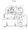
- FIG. 2 shows an example in general outline of the whole structure of a wire cutting electric discharge machine.
- the wire cutting electric discharge machine 1 comprises a process liquid receiver 5 on a base 3 and a column 7.
- a movable table 11 provided with a workpiece clamp 9 for supportingly securing a workpiece W is supported in a manner to allow two dimensional movement in both the X and Y directions.
- an upper arm 13 On the upper side surface of the column 7, an upper arm 13 is mounted. On the tip of this upper arm 13, a vertically movable slide 15 is provided in a freely vertically positional adjustable manner. On the lower tip of the slide 15, an upper nozzle holder 17 is installed. An upper process liquid supply nozzle 19 is mounted on the upper nozzle holder 17.
- a lower arm 21 is installed parallel to the upper arm 13.
- a lower nozzle supply nozzle 23 On the tip portion of the lower arm 21, there is provided through a lower nozzle supply nozzle 23 a lower process liquid supply nozzle 23 which is opposing the upper process liquid supply nozzle 19.
- the upper process liquid supply nozzle 19 and the lower process liquid supply nozzle 23 spray a process liquid such as distilled water onto the electric discharge process area of the workpiece W, which are also used to guide a wire 27 used as an electrode to maintain its direction.
- a supply reel 29 which continuously supplies the very fine wire 27 to the electric discharge area is mounted in a freely rotatable manner.
- the wire 27 from the supply reel 29 reaches the upper process liquid supply nozzle 19 via a plurality of freely rotatable upper guide rollers 31 which are provided ranging from the column 7 to the upper nozzle holder 17, and the wire 27 runs from the upper process liquid supply nozzle 19, through the electric discharge area of the workpiece W, to reach the lower process liquid supply nozzle 23.
- the wire 27 is discharged to a recovery box 39 provided on the side of the base 3 by means of a wire discharge device 41.
- the wire discharge device 41 comprises a very hard feed roller 33, for example made of ceramic, for winding up the wire, which is provided on the lower nozzle holder 25; a pair of conveyor belts 35 which interposedly support and convey the wire 27; and a pair of wire discharge rollers 37 of the same quality as the feed roller 33, which is provided at the rear of the conveyor belts 35.
- the wire 27 fed out from the supply reel 29, is guided to the upper process liquid supply nozzle 19 by means of the upper guide rollers 31, and reaches the lower process liquid supply nozzle 23.
- the workpiece W placed on the work table 11 which is movable by means of a drive system which is driven by a motor through a screw member or the like is processed by the wire 27 which is stretched between the upper process liquid supply nozzle 19 and the lower process liquid supply nozzle 23.
- the wire 27 used in the electric discharge process is guided by means of the feed roller 33 used for winding up the wire.
- the feed roller 33 is made of a very hard material, for example, from a ceramic or the like, and is provided on the lower nozzle holder 25.
- the wire 27 is conveyed while being interposedly supported by the top and bottom opposed endless conveyor belts 35, is pinched between the wire discharge rollers 37 provided at the rear side (the discharge side) for pulling the wire, is stretched, and is discharged by the rollers 37.
- the wire 27 discharged by the wire discharge rollers 37 is stored in the recovery box 39.
- the feed roller 33 and the wire discharge rollers 37 are driven through a drive system by a motor or the like which is omitted from the drawing.
- Each of the conveyor belts 35 is provided with non-driven rollers 43 at the both ends thereof, and at least one or more twists are imparted to the belts within the conveying interval "A".
- a plurality of guide rollers 47 are positioned in a suitable number of locations in order to maintain this twist.
- the electrode wire 27 which has completed the electrical discharge process and has passed through the lower process liquid supply nozzle 23 is interposedly supported and transported by the feed roller 33 and the lower conveyor belt 35 driven by the roller 33.
- the feed roller 33 is made of a very hard material such as ceramic or the like, wear or the like from the wire 27 is extremely small so that the wire can be fed into the conveying interval "A" between the belts smoothly with no vibration in the wire 27.
- the rollers 43 provided at both side of the conveyor belts 35 are not necessary to be driven and do not serve forced forward movement of the wire 27. Also, since the wire 27 passes the twisted portion within the conveying interval "A". The wire 27 receives an aligning action therethrough and can be transported in a straight line even if any wear is occurred on the conveyor belts 35.
- both the wire discharge rollers 37 provided at the discharge end of the conveyor belts 35 are made of a very hard material such as ceramic or the like in the same manner as the feed roller 33 and are driven, the wire 27 can be discharged even if there is any wear on the conveyor belts 35.
- the replacement cycle of the conveyor belts 35 can be extended.
- the wire discharge device for a wire cutting electric discharge machine of the present invention is provided with a belt conveyor mechanism having an upper and a lower conveyor belt by which the wire is conveyed in an interposedly supported manner therebetween and a feed roll and discharge rolls both made of a very hard material which are provided at the front and rear sides the belt conveyor mechanism, and the at least one twist is imparted to the belts within the conveying interval of the conveyor belts, so that the wire can be smoothly discharged with no relation to any wear caused in the belts, and as a result the replacement cycle of the belts can be extended. Therefore, the wire discharge device is usful in a wire cutting electric discharge machine.
Landscapes
- Chemical & Material Sciences (AREA)
- Chemical Kinetics & Catalysis (AREA)
- Electrochemistry (AREA)
- Engineering & Computer Science (AREA)
- Mechanical Engineering (AREA)
- Electrical Discharge Machining, Electrochemical Machining, And Combined Machining (AREA)
- Attitude Control For Articles On Conveyors (AREA)
Applications Claiming Priority (2)
| Application Number | Priority Date | Filing Date | Title |
|---|---|---|---|
| JP29094/88 | 1988-02-10 | ||
| JP63029094A JP2783804B2 (ja) | 1988-02-10 | 1988-02-10 | ワイヤカット放電加工機のワイヤ排出装置 |
Publications (2)
| Publication Number | Publication Date |
|---|---|
| EP0366801A1 true EP0366801A1 (de) | 1990-05-09 |
| EP0366801A4 EP0366801A4 (de) | 1990-07-04 |
Family
ID=12266767
Family Applications (1)
| Application Number | Title | Priority Date | Filing Date |
|---|---|---|---|
| EP19890902297 Withdrawn EP0366801A4 (de) | 1988-02-10 | 1989-02-10 | Drahtabrollstruktur für drahtschneidefunkerosionbearbeitungsmaschine. |
Country Status (6)
| Country | Link |
|---|---|
| US (1) | US5032701A (de) |
| EP (1) | EP0366801A4 (de) |
| JP (1) | JP2783804B2 (de) |
| CH (1) | CH676339A5 (de) |
| GB (1) | GB2229955B (de) |
| WO (1) | WO1989007506A1 (de) |
Families Citing this family (4)
| Publication number | Priority date | Publication date | Assignee | Title |
|---|---|---|---|---|
| JPH0326421A (ja) * | 1989-06-24 | 1991-02-05 | Amada Washino Co Ltd | ワイヤカット放電加工機 |
| US5791451A (en) * | 1996-08-19 | 1998-08-11 | E.F. Bavis & Associates, Inc. | Tape drive conveyor system with twisted conformation |
| JP5767623B2 (ja) * | 2012-12-27 | 2015-08-19 | 住友ゴム工業株式会社 | ゴムストリップの貼付装置 |
| JP5945290B2 (ja) * | 2014-02-24 | 2016-07-05 | 住友ゴム工業株式会社 | タイヤ部材形成装置 |
Family Cites Families (7)
| Publication number | Priority date | Publication date | Assignee | Title |
|---|---|---|---|---|
| US3368728A (en) * | 1966-01-13 | 1968-02-13 | Artos Engineering Co | Endless belt |
| JPS5727624A (en) * | 1980-07-28 | 1982-02-15 | Japax Inc | Automatic wire setting device of wire type electric discharge processing machine |
| JPS57149124A (en) * | 1981-03-11 | 1982-09-14 | Mitsubishi Electric Corp | Wire electrode feeder of wire cut electric discharge machining device |
| CH641991A5 (en) * | 1981-07-24 | 1984-03-30 | Charmilles Sa Ateliers | Device for taking hold of the wire electrode of a machine for cutting using erosive electrical discharges |
| JPS6128715U (ja) * | 1984-07-23 | 1986-02-20 | ロ−ム株式会社 | 連続状電子部品の搬送装置 |
| JPS6244319A (ja) * | 1985-08-21 | 1987-02-26 | Fanuc Ltd | ワイヤカツト放電加工機のワイヤ自動結線装置 |
| JPH06244319A (ja) * | 1993-02-15 | 1994-09-02 | Matsushita Electric Ind Co Ltd | 半導体装置の封止用エポキシ樹脂組成物 |
-
1988
- 1988-02-10 JP JP63029094A patent/JP2783804B2/ja not_active Expired - Lifetime
-
1989
- 1989-02-10 GB GB8922663A patent/GB2229955B/en not_active Expired
- 1989-02-10 EP EP19890902297 patent/EP0366801A4/de not_active Withdrawn
- 1989-02-10 WO PCT/JP1989/000137 patent/WO1989007506A1/ja not_active Ceased
- 1989-02-10 CH CH3756/89A patent/CH676339A5/de not_active IP Right Cessation
- 1989-02-10 US US07/425,199 patent/US5032701A/en not_active Expired - Lifetime
Non-Patent Citations (2)
| Title |
|---|
| No relevant documents have been disclosed * |
| See also references of WO8907506A1 * |
Also Published As
| Publication number | Publication date |
|---|---|
| GB8922663D0 (en) | 1990-07-04 |
| CH676339A5 (de) | 1991-01-15 |
| GB2229955B (en) | 1991-06-12 |
| JPH01205936A (ja) | 1989-08-18 |
| WO1989007506A1 (fr) | 1989-08-24 |
| US5032701A (en) | 1991-07-16 |
| JP2783804B2 (ja) | 1998-08-06 |
| EP0366801A4 (de) | 1990-07-04 |
| GB2229955A (en) | 1990-10-10 |
Similar Documents
| Publication | Publication Date | Title |
|---|---|---|
| EP0366801A1 (de) | Drahtabrollstruktur für drahtschneidefunkerosionbearbeitungsmaschine | |
| US6220940B1 (en) | Micro-finishing apparatus | |
| AU1304200A (en) | Apparatus for the positioning of a tool or a tool holder in a machine designed for processing a sheet material | |
| JP2608225B2 (ja) | プリント基板の自動ローディング装置 | |
| JPS6290323A (ja) | フリ−ス取り出し装置 | |
| ES262683U (es) | "dispositivo marcador, con cintas de goma, para la alimentacion intermitente, de cartones o plantillas". | |
| JPH06143043A (ja) | 微細穴放電加工方法および装置 | |
| CA1056707A (en) | Method and machine for bending flat strip to a cylindrical shape | |
| EP0356526B1 (de) | Funkenerosionsdrahtschneidevorrichtung | |
| JPS63306829A (ja) | ワイヤカット放電加工装置 | |
| EP0694385A1 (de) | Automatische Siebdruckmaschine | |
| JP2620862B2 (ja) | ワイヤ放電加工機による大テーパ加工方法 | |
| US6386959B2 (en) | Feeding system for electro-chemically polishing contact tips | |
| JP3439952B2 (ja) | 切断機 | |
| CN213793536U (zh) | 一种带宽调整装置 | |
| KR100423956B1 (ko) | 실 권취용 지관의 재단원지 및 재단장치 | |
| KR910003787Y1 (ko) | 가공 직물의 샐비지 (Salvage) 회수처리 장치 | |
| JP2955426B2 (ja) | 紡機におけるぺッグトレイ搬送装置 | |
| KR200151795Y1 (ko) | 박판 공급장치 | |
| JP2649449B2 (ja) | ワイドベルトサンダー機の加工材供給装置 | |
| JPH03239421A (ja) | ワイヤ放電加工機におけるワイヤ搬送装置 | |
| SU706140A1 (ru) | Устройство дл очистки проволоки | |
| KR200282890Y1 (ko) | 실 권취용 지관의 재단원지 및 재단장치 | |
| JPS62203722A (ja) | ワイヤカツト放電加工装置 | |
| JPS62126069A (ja) | 金属製帯状材料供給装置 |
Legal Events
| Date | Code | Title | Description |
|---|---|---|---|
| PUAI | Public reference made under article 153(3) epc to a published international application that has entered the european phase |
Free format text: ORIGINAL CODE: 0009012 |
|
| 17P | Request for examination filed |
Effective date: 19900129 |
|
| AK | Designated contracting states |
Kind code of ref document: A1 Designated state(s): CH DE FR GB IT LI |
|
| A4 | Supplementary search report drawn up and despatched |
Effective date: 19900704 |
|
| RAP1 | Party data changed (applicant data changed or rights of an application transferred) |
Owner name: AMADA COMPANY LIMITED Owner name: AMADA WASINO COMPANY, LIMITED |
|
| 17Q | First examination report despatched |
Effective date: 19921102 |
|
| STAA | Information on the status of an ep patent application or granted ep patent |
Free format text: STATUS: THE APPLICATION HAS BEEN WITHDRAWN |
|
| 18W | Application withdrawn |
Withdrawal date: 19930125 |