EP0366913B1 - Fotoelektrische Schaltvorrichtung für Koordinatenerkennungssystem - Google Patents
Fotoelektrische Schaltvorrichtung für Koordinatenerkennungssystem Download PDFInfo
- Publication number
- EP0366913B1 EP0366913B1 EP89116971A EP89116971A EP0366913B1 EP 0366913 B1 EP0366913 B1 EP 0366913B1 EP 89116971 A EP89116971 A EP 89116971A EP 89116971 A EP89116971 A EP 89116971A EP 0366913 B1 EP0366913 B1 EP 0366913B1
- Authority
- EP
- European Patent Office
- Prior art keywords
- light emitting
- photo
- light
- detecting
- infrared
- Prior art date
- Legal status (The legal status is an assumption and is not a legal conclusion. Google has not performed a legal analysis and makes no representation as to the accuracy of the status listed.)
- Expired - Lifetime
Links
Images


Classifications
-
- G—PHYSICS
- G06—COMPUTING OR CALCULATING; COUNTING
- G06F—ELECTRIC DIGITAL DATA PROCESSING
- G06F3/00—Input arrangements for transferring data to be processed into a form capable of being handled by the computer; Output arrangements for transferring data from processing unit to output unit, e.g. interface arrangements
- G06F3/01—Input arrangements or combined input and output arrangements for interaction between user and computer
- G06F3/03—Arrangements for converting the position or the displacement of a member into a coded form
-
- G—PHYSICS
- G06—COMPUTING OR CALCULATING; COUNTING
- G06F—ELECTRIC DIGITAL DATA PROCESSING
- G06F3/00—Input arrangements for transferring data to be processed into a form capable of being handled by the computer; Output arrangements for transferring data from processing unit to output unit, e.g. interface arrangements
- G06F3/01—Input arrangements or combined input and output arrangements for interaction between user and computer
- G06F3/03—Arrangements for converting the position or the displacement of a member into a coded form
- G06F3/041—Digitisers, e.g. for touch screens or touch pads, characterised by the transducing means
- G06F3/042—Digitisers, e.g. for touch screens or touch pads, characterised by the transducing means by opto-electronic means
- G06F3/0421—Digitisers, e.g. for touch screens or touch pads, characterised by the transducing means by opto-electronic means by interrupting or reflecting a light beam, e.g. optical touch-screen
-
- G—PHYSICS
- G06—COMPUTING OR CALCULATING; COUNTING
- G06F—ELECTRIC DIGITAL DATA PROCESSING
- G06F3/00—Input arrangements for transferring data to be processed into a form capable of being handled by the computer; Output arrangements for transferring data from processing unit to output unit, e.g. interface arrangements
- G06F3/01—Input arrangements or combined input and output arrangements for interaction between user and computer
- G06F3/02—Input arrangements using manually operated switches, e.g. using keyboards or dials
Definitions
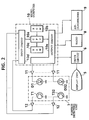
- T12, T22 and T32 constitute a second array of photo-detecting elements consisting of photo-transistors which are mounted on the right side of the display 5a for receiving the light from the second light emitting elements D12, D22 and D32 and generating a second block signal when any one of the light paths P12, P22 and P32 is blocked by a finger.
- the light path P1 passes through the regions Z 11, Z12 and Z13, the light path P2 through the regions Z21, Z22 and Z23, the light path P3 through the regions Z31, Z32 and Z33, and the light path P4 through the regions Z41, Z42 and Z43 in the similar manner.
Landscapes
- Engineering & Computer Science (AREA)
- General Engineering & Computer Science (AREA)
- Theoretical Computer Science (AREA)
- Human Computer Interaction (AREA)
- Physics & Mathematics (AREA)
- General Physics & Mathematics (AREA)
- Switches Operated By Changes In Physical Conditions (AREA)
- Position Input By Displaying (AREA)
- Electronic Switches (AREA)
Claims (9)
- Photoelektrische Vorrichtung zur Erkennung der Absolutposition (Z11, ..., Z43) eines Objekts, aufweisend:
ein erstes Infrarotlicht emittierendes Element (D11, D21, D31),
ein erstes Infrarot-Photodetektorelement (T11, T21, T31) zum Empfang des von dem ersten Infrarotlicht emittierenden Element entlang eines ersten Lichtwegs (P11, P21, P31) emittierten Lichts und zur Erzeugung eines ersten Ausgangssignals,
ein zweites Infrarotlicht emittierendes Element (D12, D22, D32),
ein zweites Infrarot-Photodetektorelement (T12, T22, T32) zum Empfang des von dem zweiten Infrarotlicht emittierenden Element entlang eines zweiten Lichtwegs (P12, P22, P32) emittierten Lichts und zur Erzeugung eines zweiten Ausgangssignals, wobei die Lichtempfangsfläche des zweiten Infrarot-Photodetektorelements in eine andere Richtung als die des ersten Infrarot-Photodetektorelements weist und sowohl der erste als auch der zweite Lichtweg den gleichen Bereich (Z11, ..., Z43) durchqueren,
ein drittes Infrarotlicht emittierendes Element (D1, ..., D4), dessen Lichtweg diejenigen des ersten und des zweiten Infrarotlicht emittierenden Elements kreuzt,
ein drittes Infrarot-Photodetektorelement (T1, ..., T4) zum Empfang des von dem dritten Infrarotlicht emittierenden Element emittierten Lichts und zur Erzeugung eines dritten Ausgangssignals, und
eine Steuereinrichtung (10) zur Entgegennahme des ersten, des zweiten und des dritten Ausgangssignals und zur Bestimmung der Absolutposition des Objekts,
dadurch gekennzeichnet,
daß die Steuereinrichtung (10) eine Disjunktions-Einrichtung aufweist, um das erste und das zweite Ausgangssignal entgegenzunehmen und beide einer unbedingten ODER-Verknüpfung zu unterwerfen, und daß die Absolutposition aus dem Ergebnis der unbedingten ODER-Verknüpfung und dem dritten Ausgangssignal bestimmt wird. - Vorrichtung nach Anspruch 1, wobei das erste und das zweite lichtemittierende Element entsprechenderweise aus einem ersten und einem zweiten Feld lichtemittierender Dioden (D11, D12, ...) und das erste und das zweite Photodetektorelement entsprechenderweise aus einem ersten und einem zweiten Feld aus Photodetektortransistoren (T11, T12, ...) besteht.
- Vorrichtung nach Anspruch 2, wobei das dritte lichtemittierende Element aus einem dritten Feld aus lichtemittierenden Dioden (D1, ... D4) besteht, die quer zu dem ersten und dem zweiten Feld aus lichtemittierenden Dioden (D11, D12, ...) angeordnet sind, und wobei das dritte Photodetektorelement aus einem dritten Feld aus Photodetektortransistoren (T1 ... T4) besteht, die quer zu dem ersten und dem zweiten Feld aus Photodetektortransistoren (T11, T12, ...) angeordnet sind.
- Vorrichtung nach Anspruch 3, wobei das dritte Feld aus lichtemittierenden Dioden (D1 ... D4) an der unteren und das dritte Feld aus Photodetektortransistoren (T1 ... T4) an der oberen Seite eines Rahmens angebracht sind.
- Vorrichtung nach einem der Ansprüche 1 bis 4, wobei die Steuereinrichtung (10) einen Eingangskreis (10d), einen Ausgangskreis (10e), eine zentrale Verarbeitungseinheit (10a), einen Speicher mit wahlfreiem Zugriff (10c) und einen Nur-Lese-Speicher (10b) aufweist.
- Vorrichtung nach einem der Ansprüche 1 bis 5, wobei der Lichtweg (P11, P21, P31) des ersten lichtemittierenden Elements (D11, D21, D31) und der Lichtweg (P12, P22, P32) des zweiten lichtemittierenden Elements (D12, D22, D32) so angeordnet sind, daß sie durch den gleichen Bereich verlaufen, der der Steuerung von Zusatzgeräten (5 ... 9) zugeordnet ist.
- Vorrichtung nach einem der Ansprüche 2 bis 5, wobei der Lichtweg (P11, P21, P31) einer lichtemittierenden Diode (D11, D21, D31) des ersten Felds aus lichtemittierenden Dioden und der Lichtweg (P12, P22, P32) einer lichtemittierenden Diode (D12, D22, D32) des zweiten Felds aus lichtemittierenden Dioden so angeordnet sind, daß sie durch den gleichen aufgeteilten Bereich bzw. die Bereiche (Z11 ... Z43) verlaufen, die der Steuerung von Zusatzgeräten (5 ... 9) zugeordnet sind.
- Vorrichtung nach einem der Ansprüche 1 bis 7, wobei das erste und das zweite lichtemittierende Element (D11, D12, ...) Licht in Querrichtung und vorzugsweise antiparallel aussenden.
- Vorrichtung nach einem der Ansprüche 1 bis 8, wobei das erste lichtemittierende Element (D11, ...) und das zweite Photodetektorelement (T12, ...) auf einer Seite einer Anzeigeeinheit (5, 5a) angeordnet sind, während das zweite lichtemittierende Element (D12, ...) und das erste Photodetektorelement (T11, ...) auf der anderen Seite der Anzeigeeinheit (5, 5a) angeordnet sind, wobei mehrere Bereiche (Z11, ..., Z43) auf die entsprechenden Lichtwege ausgerichtet auf der Anzeigeeinheit (5, 5a) angezeigt werden, um Betriebsfunktionen von Zusatzgeräten (5 ... 9) anzugeben, und wobei die Anzeigeeinheit zur Verwendung in einem Fahrzeug eingerichtet ist.
Applications Claiming Priority (2)
| Application Number | Priority Date | Filing Date | Title |
|---|---|---|---|
| JP277997/88 | 1988-11-01 | ||
| JP63277997A JPH02123626A (ja) | 1988-11-01 | 1988-11-01 | 光スイツチ装置 |
Publications (3)
| Publication Number | Publication Date |
|---|---|
| EP0366913A2 EP0366913A2 (de) | 1990-05-09 |
| EP0366913A3 EP0366913A3 (en) | 1990-09-12 |
| EP0366913B1 true EP0366913B1 (de) | 1995-11-22 |
Family
ID=17591189
Family Applications (1)
| Application Number | Title | Priority Date | Filing Date |
|---|---|---|---|
| EP89116971A Expired - Lifetime EP0366913B1 (de) | 1988-11-01 | 1989-09-13 | Fotoelektrische Schaltvorrichtung für Koordinatenerkennungssystem |
Country Status (4)
| Country | Link |
|---|---|
| EP (1) | EP0366913B1 (de) |
| JP (1) | JPH02123626A (de) |
| KR (1) | KR920005602B1 (de) |
| DE (1) | DE68924901T2 (de) |
Cited By (18)
| Publication number | Priority date | Publication date | Assignee | Title |
|---|---|---|---|---|
| US6947102B2 (en) | 2002-02-20 | 2005-09-20 | Plannar Systems, Inc. | Light sensitive display which senses decreases in light |
| US7009663B2 (en) | 2003-12-17 | 2006-03-07 | Planar Systems, Inc. | Integrated optical light sensitive active matrix liquid crystal display |
| US7023503B2 (en) | 2002-02-20 | 2006-04-04 | Planar Systems, Inc. | Image sensor with photosensitive thin film transistors |
| US7053967B2 (en) | 2002-05-23 | 2006-05-30 | Planar Systems, Inc. | Light sensitive display |
| US7773139B2 (en) | 2004-04-16 | 2010-08-10 | Apple Inc. | Image sensor with photosensitive thin film transistors |
| US8207946B2 (en) | 2003-02-20 | 2012-06-26 | Apple Inc. | Light sensitive display |
| US8638320B2 (en) | 2011-06-22 | 2014-01-28 | Apple Inc. | Stylus orientation detection |
| US8928635B2 (en) | 2011-06-22 | 2015-01-06 | Apple Inc. | Active stylus |
| US9176604B2 (en) | 2012-07-27 | 2015-11-03 | Apple Inc. | Stylus device |
| US9310923B2 (en) | 2010-12-03 | 2016-04-12 | Apple Inc. | Input device for touch sensitive devices |
| US9329703B2 (en) | 2011-06-22 | 2016-05-03 | Apple Inc. | Intelligent stylus |
| US9557845B2 (en) | 2012-07-27 | 2017-01-31 | Apple Inc. | Input device for and method of communication with capacitive devices through frequency variation |
| US9652090B2 (en) | 2012-07-27 | 2017-05-16 | Apple Inc. | Device for digital communication through capacitive coupling |
| US9939935B2 (en) | 2013-07-31 | 2018-04-10 | Apple Inc. | Scan engine for touch controller architecture |
| US10048775B2 (en) | 2013-03-14 | 2018-08-14 | Apple Inc. | Stylus detection and demodulation |
| US10061449B2 (en) | 2014-12-04 | 2018-08-28 | Apple Inc. | Coarse scan and targeted active mode scan for touch and stylus |
| US10474277B2 (en) | 2016-05-31 | 2019-11-12 | Apple Inc. | Position-based stylus communication |
| US12153764B1 (en) | 2020-09-25 | 2024-11-26 | Apple Inc. | Stylus with receive architecture for position determination |
Families Citing this family (11)
| Publication number | Priority date | Publication date | Assignee | Title |
|---|---|---|---|---|
| US7482943B2 (en) | 1991-05-31 | 2009-01-27 | Koninklijke Philips Electronics N.V. | Device with a human-machine interface |
| US7057521B1 (en) | 1991-05-31 | 2006-06-06 | Koninklijke Philips Electronics N.V. | Device with a human-machine interface |
| JPH113169A (ja) | 1997-06-13 | 1999-01-06 | Tokai Rika Co Ltd | タッチ操作情報出力装置 |
| GB2395269B (en) * | 1999-11-22 | 2004-06-30 | Namco Ltd | Received-light pattern detection apparatus |
| JP2001147106A (ja) | 1999-11-24 | 2001-05-29 | Namco Ltd | 受光パターン検出装置 |
| JP4658354B2 (ja) * | 2001-03-02 | 2011-03-23 | 株式会社京三製作所 | 障害物検知装置およびこれを備えた可動ホーム柵装置 |
| JP2003099201A (ja) * | 2001-09-21 | 2003-04-04 | Aiphone Co Ltd | 光学式タッチパネル装置 |
| CN101479691B (zh) | 2006-06-28 | 2011-12-14 | 皇家飞利浦电子股份有限公司 | 基于光学参数的用于对象学习和识别的方法及装置 |
| JP4775247B2 (ja) * | 2006-12-21 | 2011-09-21 | 三菱電機株式会社 | 位置検出装置 |
| DE102007039718B4 (de) * | 2007-08-22 | 2015-11-05 | Wincor Nixdorf International Gmbh | Tastatur mit Infrarotsensor |
| JP2023180655A (ja) * | 2022-06-10 | 2023-12-21 | セイコーエプソン株式会社 | 印刷装置 |
Citations (1)
| Publication number | Priority date | Publication date | Assignee | Title |
|---|---|---|---|---|
| US3764813A (en) * | 1972-04-12 | 1973-10-09 | Bell Telephone Labor Inc | Coordinate detection system |
Family Cites Families (3)
| Publication number | Priority date | Publication date | Assignee | Title |
|---|---|---|---|---|
| DE2621221A1 (de) * | 1976-03-13 | 1977-09-15 | Marconi Co Ltd | Steueranordnung |
| US4198623A (en) * | 1978-11-13 | 1980-04-15 | Sanders Associates, Inc. | Touch entry interactive cathode ray tube arrangement |
| JPS63172325A (ja) * | 1987-01-10 | 1988-07-16 | Pioneer Electronic Corp | タツチパネル制御装置 |
-
1988
- 1988-11-01 JP JP63277997A patent/JPH02123626A/ja active Pending
-
1989
- 1989-09-13 EP EP89116971A patent/EP0366913B1/de not_active Expired - Lifetime
- 1989-09-13 DE DE68924901T patent/DE68924901T2/de not_active Expired - Fee Related
- 1989-10-31 KR KR1019890015664A patent/KR920005602B1/ko not_active Expired
Patent Citations (1)
| Publication number | Priority date | Publication date | Assignee | Title |
|---|---|---|---|---|
| US3764813A (en) * | 1972-04-12 | 1973-10-09 | Bell Telephone Labor Inc | Coordinate detection system |
Cited By (44)
| Publication number | Priority date | Publication date | Assignee | Title |
|---|---|---|---|---|
| US7872641B2 (en) | 2002-02-20 | 2011-01-18 | Apple Inc. | Light sensitive display |
| US8441422B2 (en) | 2002-02-20 | 2013-05-14 | Apple Inc. | Light sensitive display with object detection calibration |
| US9134851B2 (en) | 2002-02-20 | 2015-09-15 | Apple Inc. | Light sensitive display |
| US7023503B2 (en) | 2002-02-20 | 2006-04-04 | Planar Systems, Inc. | Image sensor with photosensitive thin film transistors |
| US9411470B2 (en) | 2002-02-20 | 2016-08-09 | Apple Inc. | Light sensitive display with multiple data set object detection |
| US7280102B2 (en) | 2002-02-20 | 2007-10-09 | Planar Systems, Inc. | Light sensitive display |
| US7408598B2 (en) | 2002-02-20 | 2008-08-05 | Planar Systems, Inc. | Light sensitive display with selected interval of light sensitive elements |
| US11073926B2 (en) | 2002-02-20 | 2021-07-27 | Apple Inc. | Light sensitive display |
| US8570449B2 (en) | 2002-02-20 | 2013-10-29 | Apple Inc. | Light sensitive display with pressure sensor |
| US6947102B2 (en) | 2002-02-20 | 2005-09-20 | Plannar Systems, Inc. | Light sensitive display which senses decreases in light |
| US6995743B2 (en) | 2002-02-20 | 2006-02-07 | Planar Systems, Inc. | Light sensitive display |
| US7880733B2 (en) | 2002-05-23 | 2011-02-01 | Apple Inc. | Light sensitive display |
| US7852417B2 (en) | 2002-05-23 | 2010-12-14 | Apple Inc. | Light sensitive display |
| US8044930B2 (en) | 2002-05-23 | 2011-10-25 | Apple Inc. | Light sensitive display |
| US7880819B2 (en) | 2002-05-23 | 2011-02-01 | Apple Inc. | Light sensitive display |
| US7830461B2 (en) | 2002-05-23 | 2010-11-09 | Apple Inc. | Light sensitive display |
| US7053967B2 (en) | 2002-05-23 | 2006-05-30 | Planar Systems, Inc. | Light sensitive display |
| US9354735B2 (en) | 2002-05-23 | 2016-05-31 | Apple Inc. | Light sensitive display |
| US8207946B2 (en) | 2003-02-20 | 2012-06-26 | Apple Inc. | Light sensitive display |
| US7009663B2 (en) | 2003-12-17 | 2006-03-07 | Planar Systems, Inc. | Integrated optical light sensitive active matrix liquid crystal display |
| US8289429B2 (en) | 2004-04-16 | 2012-10-16 | Apple Inc. | Image sensor with photosensitive thin film transistors and dark current compensation |
| US7773139B2 (en) | 2004-04-16 | 2010-08-10 | Apple Inc. | Image sensor with photosensitive thin film transistors |
| US9310923B2 (en) | 2010-12-03 | 2016-04-12 | Apple Inc. | Input device for touch sensitive devices |
| US9921684B2 (en) | 2011-06-22 | 2018-03-20 | Apple Inc. | Intelligent stylus |
| US8638320B2 (en) | 2011-06-22 | 2014-01-28 | Apple Inc. | Stylus orientation detection |
| US8928635B2 (en) | 2011-06-22 | 2015-01-06 | Apple Inc. | Active stylus |
| US9519361B2 (en) | 2011-06-22 | 2016-12-13 | Apple Inc. | Active stylus |
| US9329703B2 (en) | 2011-06-22 | 2016-05-03 | Apple Inc. | Intelligent stylus |
| US9652090B2 (en) | 2012-07-27 | 2017-05-16 | Apple Inc. | Device for digital communication through capacitive coupling |
| US9582105B2 (en) | 2012-07-27 | 2017-02-28 | Apple Inc. | Input device for touch sensitive devices |
| US9557845B2 (en) | 2012-07-27 | 2017-01-31 | Apple Inc. | Input device for and method of communication with capacitive devices through frequency variation |
| US9176604B2 (en) | 2012-07-27 | 2015-11-03 | Apple Inc. | Stylus device |
| US10048775B2 (en) | 2013-03-14 | 2018-08-14 | Apple Inc. | Stylus detection and demodulation |
| US10845901B2 (en) | 2013-07-31 | 2020-11-24 | Apple Inc. | Touch controller architecture |
| US9939935B2 (en) | 2013-07-31 | 2018-04-10 | Apple Inc. | Scan engine for touch controller architecture |
| US12340048B2 (en) | 2013-07-31 | 2025-06-24 | Apple Inc. | Touch controller architecture |
| US10067580B2 (en) | 2013-07-31 | 2018-09-04 | Apple Inc. | Active stylus for use with touch controller architecture |
| US11687192B2 (en) | 2013-07-31 | 2023-06-27 | Apple Inc. | Touch controller architecture |
| US10061449B2 (en) | 2014-12-04 | 2018-08-28 | Apple Inc. | Coarse scan and targeted active mode scan for touch and stylus |
| US10664113B2 (en) | 2014-12-04 | 2020-05-26 | Apple Inc. | Coarse scan and targeted active mode scan for touch and stylus |
| US10067618B2 (en) | 2014-12-04 | 2018-09-04 | Apple Inc. | Coarse scan and targeted active mode scan for touch |
| US10061450B2 (en) | 2014-12-04 | 2018-08-28 | Apple Inc. | Coarse scan and targeted active mode scan for touch |
| US10474277B2 (en) | 2016-05-31 | 2019-11-12 | Apple Inc. | Position-based stylus communication |
| US12153764B1 (en) | 2020-09-25 | 2024-11-26 | Apple Inc. | Stylus with receive architecture for position determination |
Also Published As
| Publication number | Publication date |
|---|---|
| HK1003018A1 (en) | 1998-09-30 |
| DE68924901D1 (de) | 1996-01-04 |
| EP0366913A3 (en) | 1990-09-12 |
| KR920005602B1 (ko) | 1992-07-09 |
| EP0366913A2 (de) | 1990-05-09 |
| DE68924901T2 (de) | 1996-08-14 |
| KR900008567A (ko) | 1990-06-04 |
| JPH02123626A (ja) | 1990-05-11 |
Similar Documents
| Publication | Publication Date | Title |
|---|---|---|
| EP0366913A2 (de) | Fotoelektrische Schaltvorrichtung für Koordinatenerkennungssystem | |
| US5136156A (en) | Photoelectric switch | |
| US6707448B1 (en) | Touch control position determining method control pad | |
| US4698626A (en) | Coordinate-data input device for CRT display having cursor travel control means | |
| US9442619B2 (en) | Method and device for providing a user interface, in particular in a vehicle | |
| AU772853B2 (en) | Apparatus and method to improve resolution of infrared touch systems | |
| EP0330767B1 (de) | Berührungsschalttafel-Steuereinrichtung mit Berührungszeit- und Fingerrichtungsunterscheidung | |
| US20070268270A1 (en) | Touch operation input device | |
| US5293513A (en) | Switching system for automotive vehicle including a reflector positioned below a sight line of a driver | |
| CN102473063A (zh) | 汽车中的操纵装置的运行方法和操纵装置 | |
| US5710623A (en) | Point-type radio controller using infared rays | |
| US7119666B2 (en) | Method for controlling and evaluating a sensor device shared by a plurality of applications | |
| HK1003018B (en) | Photoelectric switching device for a coordinate detection system | |
| US11402921B2 (en) | Operation control apparatus | |
| JPH09109802A (ja) | 自動車用操作装置 | |
| US6847870B2 (en) | Self diagnostic apparatus for vehicle information display system | |
| JPH10133818A (ja) | タッチパネル入力方法及び装置 | |
| EP3851945B1 (de) | Näherungsdetektionsvorrichtung | |
| EP3926444B1 (de) | Näherungsdetektionsvorrichtung und informationsverarbeitungssystem | |
| US20250035784A1 (en) | Touching operator identification system and information processing system | |
| EP0520655A2 (de) | Artikelauswahlverfahren und Gerät | |
| JP2010112758A (ja) | 車載用遠隔操作装置 | |
| JPH08202480A (ja) | 操作入力装置 | |
| JPH054035Y2 (de) | ||
| JP2567296Y2 (ja) | タッチパネルの構造 |
Legal Events
| Date | Code | Title | Description |
|---|---|---|---|
| PUAI | Public reference made under article 153(3) epc to a published international application that has entered the european phase |
Free format text: ORIGINAL CODE: 0009012 |
|
| AK | Designated contracting states |
Kind code of ref document: A2 Designated state(s): DE FR GB SE |
|
| PUAL | Search report despatched |
Free format text: ORIGINAL CODE: 0009013 |
|
| RHK1 | Main classification (correction) |
Ipc: G06K 11/08 |
|
| AK | Designated contracting states |
Kind code of ref document: A3 Designated state(s): DE FR GB SE |
|
| 17P | Request for examination filed |
Effective date: 19900920 |
|
| 17Q | First examination report despatched |
Effective date: 19930331 |
|
| GRAA | (expected) grant |
Free format text: ORIGINAL CODE: 0009210 |
|
| AK | Designated contracting states |
Kind code of ref document: B1 Designated state(s): DE FR GB SE |
|
| REF | Corresponds to: |
Ref document number: 68924901 Country of ref document: DE Date of ref document: 19960104 |
|
| ET | Fr: translation filed | ||
| PLBE | No opposition filed within time limit |
Free format text: ORIGINAL CODE: 0009261 |
|
| STAA | Information on the status of an ep patent application or granted ep patent |
Free format text: STATUS: NO OPPOSITION FILED WITHIN TIME LIMIT |
|
| 26N | No opposition filed | ||
| REG | Reference to a national code |
Ref country code: GB Ref legal event code: 746 Effective date: 19990519 |
|
| REG | Reference to a national code |
Ref country code: FR Ref legal event code: D6 |
|
| REG | Reference to a national code |
Ref country code: GB Ref legal event code: IF02 |
|
| PGFP | Annual fee paid to national office [announced via postgrant information from national office to epo] |
Ref country code: SE Payment date: 20040906 Year of fee payment: 16 |
|
| PGFP | Annual fee paid to national office [announced via postgrant information from national office to epo] |
Ref country code: GB Payment date: 20040908 Year of fee payment: 16 Ref country code: FR Payment date: 20040908 Year of fee payment: 16 |
|
| PGFP | Annual fee paid to national office [announced via postgrant information from national office to epo] |
Ref country code: DE Payment date: 20040909 Year of fee payment: 16 |
|
| PG25 | Lapsed in a contracting state [announced via postgrant information from national office to epo] |
Ref country code: GB Free format text: LAPSE BECAUSE OF NON-PAYMENT OF DUE FEES Effective date: 20050913 |
|
| PG25 | Lapsed in a contracting state [announced via postgrant information from national office to epo] |
Ref country code: SE Free format text: LAPSE BECAUSE OF NON-PAYMENT OF DUE FEES Effective date: 20050914 |
|
| PG25 | Lapsed in a contracting state [announced via postgrant information from national office to epo] |
Ref country code: DE Free format text: LAPSE BECAUSE OF NON-PAYMENT OF DUE FEES Effective date: 20060401 |
|
| EUG | Se: european patent has lapsed | ||
| GBPC | Gb: european patent ceased through non-payment of renewal fee |
Effective date: 20050913 |
|
| PG25 | Lapsed in a contracting state [announced via postgrant information from national office to epo] |
Ref country code: FR Free format text: LAPSE BECAUSE OF NON-PAYMENT OF DUE FEES Effective date: 20060531 |
|
| REG | Reference to a national code |
Ref country code: FR Ref legal event code: ST Effective date: 20060531 |