EP0366951B1 - Lenksäule für Kraftfahrzeuge mit in Achsrichtung verstellbarer Lenkwelle - Google Patents
Lenksäule für Kraftfahrzeuge mit in Achsrichtung verstellbarer Lenkwelle Download PDFInfo
- Publication number
- EP0366951B1 EP0366951B1 EP89118287A EP89118287A EP0366951B1 EP 0366951 B1 EP0366951 B1 EP 0366951B1 EP 89118287 A EP89118287 A EP 89118287A EP 89118287 A EP89118287 A EP 89118287A EP 0366951 B1 EP0366951 B1 EP 0366951B1
- Authority
- EP
- European Patent Office
- Prior art keywords
- toothing
- tooth
- steering column
- locking
- elements
- Prior art date
- Legal status (The legal status is an assumption and is not a legal conclusion. Google has not performed a legal analysis and makes no representation as to the accuracy of the status listed.)
- Expired - Lifetime
Links
- 230000000694 effects Effects 0.000 description 2
- 230000005540 biological transmission Effects 0.000 description 1
- 230000015572 biosynthetic process Effects 0.000 description 1
- 238000006073 displacement reaction Methods 0.000 description 1
- 230000007257 malfunction Effects 0.000 description 1
Images

Classifications
-
- B—PERFORMING OPERATIONS; TRANSPORTING
- B62—LAND VEHICLES FOR TRAVELLING OTHERWISE THAN ON RAILS
- B62D—MOTOR VEHICLES; TRAILERS
- B62D1/00—Steering controls, i.e. means for initiating a change of direction of the vehicle
- B62D1/02—Steering controls, i.e. means for initiating a change of direction of the vehicle vehicle-mounted
- B62D1/16—Steering columns
- B62D1/18—Steering columns yieldable or adjustable, e.g. tiltable
-
- B—PERFORMING OPERATIONS; TRANSPORTING
- B62—LAND VEHICLES FOR TRAVELLING OTHERWISE THAN ON RAILS
- B62D—MOTOR VEHICLES; TRAILERS
- B62D1/00—Steering controls, i.e. means for initiating a change of direction of the vehicle
- B62D1/02—Steering controls, i.e. means for initiating a change of direction of the vehicle vehicle-mounted
- B62D1/16—Steering columns
- B62D1/18—Steering columns yieldable or adjustable, e.g. tiltable
- B62D1/184—Mechanisms for locking columns at selected positions
-
- B—PERFORMING OPERATIONS; TRANSPORTING
- B62—LAND VEHICLES FOR TRAVELLING OTHERWISE THAN ON RAILS
- B62D—MOTOR VEHICLES; TRAILERS
- B62D1/00—Steering controls, i.e. means for initiating a change of direction of the vehicle
- B62D1/02—Steering controls, i.e. means for initiating a change of direction of the vehicle vehicle-mounted
- B62D1/16—Steering columns
- B62D1/18—Steering columns yieldable or adjustable, e.g. tiltable
- B62D1/185—Steering columns yieldable or adjustable, e.g. tiltable adjustable by axial displacement, e.g. telescopically
-
- Y—GENERAL TAGGING OF NEW TECHNOLOGICAL DEVELOPMENTS; GENERAL TAGGING OF CROSS-SECTIONAL TECHNOLOGIES SPANNING OVER SEVERAL SECTIONS OF THE IPC; TECHNICAL SUBJECTS COVERED BY FORMER USPC CROSS-REFERENCE ART COLLECTIONS [XRACs] AND DIGESTS
- Y10—TECHNICAL SUBJECTS COVERED BY FORMER USPC
- Y10T—TECHNICAL SUBJECTS COVERED BY FORMER US CLASSIFICATION
- Y10T403/00—Joints and connections
- Y10T403/32—Articulated members
- Y10T403/32254—Lockable at fixed position
- Y10T403/32426—Plural distinct positions
- Y10T403/32442—At least one discrete position
- Y10T403/32451—Step-by-step adjustment
- Y10T403/32459—Retainer extends through aligned recesses
-
- Y—GENERAL TAGGING OF NEW TECHNOLOGICAL DEVELOPMENTS; GENERAL TAGGING OF CROSS-SECTIONAL TECHNOLOGIES SPANNING OVER SEVERAL SECTIONS OF THE IPC; TECHNICAL SUBJECTS COVERED BY FORMER USPC CROSS-REFERENCE ART COLLECTIONS [XRACs] AND DIGESTS
- Y10—TECHNICAL SUBJECTS COVERED BY FORMER USPC
- Y10T—TECHNICAL SUBJECTS COVERED BY FORMER US CLASSIFICATION
- Y10T403/00—Joints and connections
- Y10T403/32—Articulated members
- Y10T403/32254—Lockable at fixed position
- Y10T403/32467—Telescoping members
- Y10T403/32475—Telescoping members having detent
- Y10T403/32501—Cam or wedge
-
- Y—GENERAL TAGGING OF NEW TECHNOLOGICAL DEVELOPMENTS; GENERAL TAGGING OF CROSS-SECTIONAL TECHNOLOGIES SPANNING OVER SEVERAL SECTIONS OF THE IPC; TECHNICAL SUBJECTS COVERED BY FORMER USPC CROSS-REFERENCE ART COLLECTIONS [XRACs] AND DIGESTS
- Y10—TECHNICAL SUBJECTS COVERED BY FORMER USPC
- Y10T—TECHNICAL SUBJECTS COVERED BY FORMER US CLASSIFICATION
- Y10T403/00—Joints and connections
- Y10T403/59—Manually releaseable latch type
- Y10T403/591—Manually releaseable latch type having operating mechanism
-
- Y—GENERAL TAGGING OF NEW TECHNOLOGICAL DEVELOPMENTS; GENERAL TAGGING OF CROSS-SECTIONAL TECHNOLOGIES SPANNING OVER SEVERAL SECTIONS OF THE IPC; TECHNICAL SUBJECTS COVERED BY FORMER USPC CROSS-REFERENCE ART COLLECTIONS [XRACs] AND DIGESTS
- Y10—TECHNICAL SUBJECTS COVERED BY FORMER USPC
- Y10T—TECHNICAL SUBJECTS COVERED BY FORMER US CLASSIFICATION
- Y10T403/00—Joints and connections
- Y10T403/60—Biased catch or latch
- Y10T403/602—Biased catch or latch by separate spring
-
- Y—GENERAL TAGGING OF NEW TECHNOLOGICAL DEVELOPMENTS; GENERAL TAGGING OF CROSS-SECTIONAL TECHNOLOGIES SPANNING OVER SEVERAL SECTIONS OF THE IPC; TECHNICAL SUBJECTS COVERED BY FORMER USPC CROSS-REFERENCE ART COLLECTIONS [XRACs] AND DIGESTS
- Y10—TECHNICAL SUBJECTS COVERED BY FORMER USPC
- Y10T—TECHNICAL SUBJECTS COVERED BY FORMER US CLASSIFICATION
- Y10T403/00—Joints and connections
- Y10T403/60—Biased catch or latch
- Y10T403/608—Pivoted
-
- Y—GENERAL TAGGING OF NEW TECHNOLOGICAL DEVELOPMENTS; GENERAL TAGGING OF CROSS-SECTIONAL TECHNOLOGIES SPANNING OVER SEVERAL SECTIONS OF THE IPC; TECHNICAL SUBJECTS COVERED BY FORMER USPC CROSS-REFERENCE ART COLLECTIONS [XRACs] AND DIGESTS
- Y10—TECHNICAL SUBJECTS COVERED BY FORMER USPC
- Y10T—TECHNICAL SUBJECTS COVERED BY FORMER US CLASSIFICATION
- Y10T74/00—Machine element or mechanism
- Y10T74/20—Control lever and linkage systems
- Y10T74/20576—Elements
- Y10T74/20636—Detents
-
- Y—GENERAL TAGGING OF NEW TECHNOLOGICAL DEVELOPMENTS; GENERAL TAGGING OF CROSS-SECTIONAL TECHNOLOGIES SPANNING OVER SEVERAL SECTIONS OF THE IPC; TECHNICAL SUBJECTS COVERED BY FORMER USPC CROSS-REFERENCE ART COLLECTIONS [XRACs] AND DIGESTS
- Y10—TECHNICAL SUBJECTS COVERED BY FORMER USPC
- Y10T—TECHNICAL SUBJECTS COVERED BY FORMER US CLASSIFICATION
- Y10T74/00—Machine element or mechanism
- Y10T74/21—Elements
- Y10T74/2133—Pawls and ratchets
- Y10T74/2136—Pivoted pawls
- Y10T74/214—Multiple tooth
Definitions
- the invention relates to a steering column for motor vehicles with axially adjustable steering shaft of the type according to the preamble of claim 1.
- a steering column with these generic features is known from US-A-3421385. From this document, although only a height-adjustable steering column is known, a locking mechanism is described which has a detent consisting of a toothing (62, 63) and locking elements (64, 65) with a tooth (68), the toothing consisting of two There are sections with the same tooth pitch, which are arranged offset in the axial direction half a tooth pitch to each other. In addition, each section is associated with a latching element (64,65) movably mounted about a transverse axis (66,67) such that the tooth (68) of a latching element lies on a tooth head of the associated section when the tooth (68) of the other section is full is engaged.
- Proposals for positive locking of the adjustable part of a length-adjustable steering column in a support bearing fixed to the body with teeth on one, mostly on the adjustable part and with one over Actuating device, possibly against the action of a spring which loads the latching in the locking position and has at least one tooth, but possibly also several teeth, on the other part are also known.
- these known positive catches from interlocking teeth on axially adjustable parts can only be set in finite positions. Your advantage lies in the locking lock, so that large forces can be transmitted in the axial direction.
- Form-locking detents are preferred in length-adjustable steering columns to absorb large crash forces.
- a major disadvantage of positive locking detents of known type is the "head-to-head" position of the interlocking toothing on the two parts which are adjustable in the axial direction and cannot be avoided in the case of length-adjustable steering columns. Even with pointed tooth heads, such a position in which locking cannot be guaranteed cannot be avoided. In such a case, locking and thus a defined engagement can only be achieved by pressing the adjustable part again, that is to say, for example, on the steering wheel. This may result in negative effects that are unacceptable with regard to safety in a motor vehicle. After the supposed locking of a newly set position, a stroke occurs with half the toothing of the latching elements, which suggests a clearance for the driver of the motor vehicle, which could be interpreted as a malfunction. The "head-to-head position" in the event of a crash that follows immediately can cause the toothing to slip, because, due to the inertia of all the components involved in the engagement, there is no significant stroke movement for locking.
- the object of the invention is the formation of a simple but stable form-locking detent with the generic features in such a way that a form-fitting tooth engagement that is effective with great certainty for the transmission of large axial forces is achieved even with a "head-to-head position" of individual tooth elements.
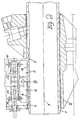
- 1 denotes a rotatably arranged jacket tube, which is adjustable in a support bearing 2 fixed to the body in the direction of the axis 3.
- a toothing in sections 4 and 5 is provided on a partial area of the circumference of the casing tube 1. Both toothed sections 4 and 5 have a toothing of the same pitch, but are offset from one another by half a tooth pitch in the axial direction.
- Each toothing section 4 and 5 is assigned a latching element 6 or 7, which in the example is movable on a common axis 8, which is transverse to axis 3.
- Each latching element 6 or 7 has at least one tooth 9 or 10, but advantageously a plurality of teeth with a pitch corresponding to the toothing in sections 4 and 5, the distance between the teeth 9 and 10 being an even multiple of the tooth pitch in the sections 4 and 5 corresponds.
- both locking elements 6 and 7 interact with wedge bodies 11 and 12, the wedge angles of which have a self-locking inclination and which point in the direction of the locking position are loaded by a spring 13, which is supported on the one hand against the wedge body 11 and on the other hand against the wedge body 12.
- Both wedge bodies 11 and 12 can be pressed against one another by overcoming the force of the spring 13 by means of an actuating device, not shown in the drawing, so that they enable the latching elements 6 and 7 to pivot about the axis 8.
- FIG. 1 shows a limit position in which the teeth 9 of the one locking element 6 are in a "head-to-head position '' with the toothing in section 4 on the casing tube 1.
- the toothing 10 on the other latching element 7 engages at least partially in the toothing of section 5.
- the toothing 9 is in the toothing of section 4 in a "head-to-head position "engage the teeth 10 and the teeth 5, so that a tooth engagement is always achieved to achieve a positive locking.
- FIG. 2 shows, compared to FIG. 1, a design in which every second tooth of the toothing in sections 4 and 5 or the toothing 9 and 10 is missing on the latching elements 6 and 7. This results in limit positions in which the teeth 10 of a locking element 7 are fully engaged is, if the toothing 9 on the other locking element 6 is in a "head-to-head position" with the counter-toothing and vice versa. In between, an infinite number of intermediate positions are possible. In these intermediate positions, there is always a full flank support of the interlocking gears.
- tooth flank contact of the toothings 9 and 10 takes place on opposite sides in all intermediate positions, that is to say, flank contact of the toothing 9 on the left-hand side involves flank contact of the toothing 10 on the right instead.
- a design in accordance with the example in FIG. 2 has the effect that due to the always complete tooth engagement of the toothing of at least one latching element, no high loads occur on the tooth flanks and dimensioning in accordance with strength is possible with relatively flat toothings equipped with a certain width on the tooth head.
- a wedging of the locking elements 6 and 7 is provided by wedge bodies 11 and 12, which can be retracted against each other by overcoming a spring by a common actuating element, in order to enable the locking elements 6 and 7 to pivot about the axis 8.
- the wedge bodies 11 and 12 engage rollers on the latching elements 6 and 7, while on the other hand they are supported on fixed abutments 14 and 15, which can also be seen in the exemplary embodiment corresponding to FIG.
- the toothings in sections 4 and 5 can be arranged on the same tooth pitch, because the removal of every second tooth creates a gap that is greater than the amount of displacement according to the example in FIG 1.
Landscapes
- Engineering & Computer Science (AREA)
- Chemical & Material Sciences (AREA)
- Combustion & Propulsion (AREA)
- Transportation (AREA)
- Mechanical Engineering (AREA)
- Steering Controls (AREA)
- Transmission Devices (AREA)
Description
- Die Erfindung betrifft eine Lenksäule für Kraftfahrzeuge mit in Achsrichtung verstellbarer Lenkwelle der Gattung nach dem Oberbegriff des Patentanspruches 1.
- Eine Lenksäule mit diesen Gattungsmerkmalen ist aus der US-A-3421385 bekannt. Aus dieser Druckschrift ist zwar eine lediglich höhenverstellbare Lenksäule bekannt, jedoch wird ein Verriegelungsmechanismus beschrieben, der eine aus einer Verzahnung (62,63) und aus Rastelementen (64,65) mit einem Zahn (68) bestehende Rastung aufweist, wobei die Verzahnung aus zwei Abschnitten mit gleicher Zahnteilung besteht, die in axialer Richtung eine halbe Zahnteilung zueinander versetzt angeordnet sind. Außerdem ist jedem Abschnitt ein um eine Querachse (66,67) beweglich gelagertes Rastelement (64,65) so zugeordnet, daß der Zahn (68) eines Rastelements auf einem Zahnkopf des zugehörigen Abschnittes liegt, wenn der Zahn (68) des anderen Abschnittes voll eingerastet ist.
- Vorschläge zur formschlüssigen Rastung des verstellbaren Teils einer längenverstellbaren Lenksäule in einem an der Karosserie festen Stützlager mit einer Verzahnung an dem einen, meistens an dem verstellbaren Teil und mit einem über eine Betätigungsvorrichtung eventuell gegen die Wirkung einer die Rastung in Riegelstellung belastenden Feder beweglichen Rastelement, welches wenigstens einen Zahn, eventuell aber auch mehrere Zähne, aufweist, an dem anderen Teil sind ebenfalls bekannt. Diese bekannten formschlüssigen Rastungen aus ineinandergreifenden Verzahnungen an axial gegeneinander verstellbaren Teilen sind jedoch nur in endlichen Positionen einstellbar. Ihr Vorteil liegt in der rastenden Verriegelung, so daß große Kräfte in axialer Richtung übertragen werden können. Formschlüssige Rastungen sind in längenverstellbaren Lenksäulen zum Auffangen großer Crash-Kräfte zu bevorzugen. Ein wesentlicher Nachteil formschlüssiger Rastungen bekannter Art ist die bei längenverstellbaren Lenksäulen nicht zu vermeidende Stellung "Kopf-auf-Kopf" der ineinandergreifenden Verzahnung an den beiden in axialer Richtung gegeneinander verstellbaren Teilen. Selbst bei spitz ausgeführten Zahnköpfen kann eine solche Stellung, in der die Verriegelung nicht gewährleistet werden kann, nicht vermieden werden. In einem solchen Falle ist eine Verriegelung und damit eine definierte Einrastung nur durch erneuten Druck auf das verstellbare Teil, daß heißt zum Beispiel auf das Lenkrad, zu erreichen. Dadurch entstehen gegebenenfalls negative Wirkungen, die im Hinblick auf die Sicherheit in einem Kraftfahrzeug inakzeptabel sind. Nach dem vermeintlichen Verriegeln einer neu eingestellten Position stellt sich ein Hub mit halber Teilung der Verzahnung der Rastelemente ein, der dem Fahrer des Kraftfahrzeugs einen Freigang suggeriert, der als Fehlfunktion gedeutet werden könnte. Die "Kopf-auf-Kopf-Stellung" bei einem unmittelbar anschließend erfolgenden Crash kann zum Durchrutschen der Verzahnung führen, weil aufgrund der Trägheiten aller am Einrasten beteiligten Bauelemente keine nennenswerte Hubbewegung zum Verriegeln erfolgt.
- Aufgabe der Erfindung ist die Ausbildung einer möglichst einfachen aber stabilen formschlüssigen Rastung mit den Gattungsmerkmalen in der Weise, daß ein mit großer Sicherheit wirksamer formschlüssiger Zahneingriff zur Übertragung großer Axialkräfte auch bei einer "Kopf-auf-Kopf-Stellung" einzelner Zahnelemente erreicht wird.
- Zur Lösung dieser Aufgabe wird erfindungsgemäß eine Ausbildung mit den Merkmalen nach dem Kennzeichen des Patentanspruches 1 vorgeschlagen.
- Die Hinterkeilung der Rastelemente durch zwei Keile mit einem selbsthemmenden Keilwinkel führt zu einem sicheren, große Axialkräfte übertragenden Zahneingriff in jeder beliebigen Lage. Zwischen Grenzstellungen, bei denen entweder die Verzahnung eines Rastsegments voll eingerastet und die Verzahnung des anderen Rastsegments mit den Zahnköpfen des zugehörigen Abschnittes der Verzahnung am Mantelrohr liegt, sind unendlich viele Zwischenstellungen möglich, bei denen die Verzahnungen der beiden Rastsegmente mehr oder weniger tief in die Verzahnung am Mantelrohr eingreifen und sich an den Zahnflanken abstützen, wobei diese Abstützung in den beiden Abschnitten auf gegenüberliegenden Zahnflanken erfolgt. Wenn sich also die Verzahnung des einen Rastelementes mit der linken Flanke an der Verzahnung auf dem Mantelrohr abstützt, dann stützt sich die Verzahnung des anderen Rastelelementes mit der rechten Flanke an der Verzahnung des zugehörigen Abschnittes auf dem Mantelrohr ab. Hieraus resultiert eine Verriegelung der axial gegeneinander verstellbaren Teile ohne merkbare Teilung.
- Auf der Zeichnung sind Ausführungsbeispiele der Erfindung dargestellt. Es zeigen:
- Figur 1
- einen Längsschnitt in einer Achsebene durch ein Ausführungsbeispiel und
- Figur 2
- einen gegenüber Figur 1 im Maßstab vergrößerten Längsschnitt in einer Achsebene durch ein abgeändertes Ausführungsbeispiel.
- Auf der Zeichnung ist mit 1 ein drehfest angeordnetes Mantelrohr bezeichnet, welches in einem an der Karosserie festen Stützlager 2 in Richtung der Achse 3 verstellbar ist. Zur Verriegelung der eingestellten Lage des Mantelrohres 1 gegenüber dem Stützlager 2 ist auf einem Teilbereich des Umfanges des Mantelrohres 1 eine Verzahnung in Abschnitten 4 und 5 vorgesehen. Beide Verzahnungsabschnitte 4 und 5 weisen eine Verzahnung gleicher Teilung auf, sind jedoch um eine halbe Zahnteilung in Achsrichtung versetzt zueinander angeordnet. Jedem Verzahnungsabschnitt 4 und 5 ist ein Rastelement 6 bzw. 7 zugeordnet, die im Falle des Beispieles auf einer gemeinsamen Achse 8, welche quer zur Achse 3 liegt, beweglich sind. Jedes Rastelement 6 bzw. 7 weist wenigstens einen Zahn 9 bzw. 10, vorteilhaft jedoch mehrere Zähne mit einer Teilung entsprechend der Verzahnung in den Abschnitten 4 und 5 auf, wobei der Abstand der Verzahnungen 9 und 10 jedoch einem geraden Vielfachen der Zahnteilung in den Abschnitten 4 und 5 entspricht. Auf der Außenseite wirken beide Rastelemente 6 und 7 mit Keilkörpern 11 und 12 zusammen, deren Keilwinkel eine selbsthemmende Neigung haben und die in Richtung der Verriegelungsstellung durch eine Feder 13 belastet sind, welche sich einerseits gegen den Keilkörper 11 und andererseits gegen den Keilkörper 12 abstützt. Beide Keilkörper 11 und 12 sind durch eine auf der Zeichnung nicht dargestellte Betätigungsvorrichtung unter Überwindung der Kraft der Feder 13 gegeneinander drückbar, so daß sie eine Schwenkbewegung der Rastelemente 6 und 7 um die Achse 8 ermöglichen. Zur Verminderung der Reibung zwischen den Rastelementen 6 und 7 einerseits und den Keilkörpern 11 und 12 andererseits können an den Rastelementen Rollen oder andere Mittel zur Verringerung der Reibung vorgesehen sein. Die Darstellung in der Figur 1 zeigt eine Grenzstellung, bei der die Zähne 9 des einen Rastelements 6 sich in einer "Kopf-auf-Kopf-Stellung'′ mit der Verzahnung in dem Abschnitt 4 am Mantelrohr 1 befindet. Durch die Versetzung der beiden Verzahnungsabschnitte 4 und 5 in Achsrichtung um eine halbe Zahnteilung greift jedoch die Verzahnung 10 an dem anderen Rastelement 7 wenigstens teilweise in die Verzahnung des Abschnittes 5 ein. Umgekehrt wird die Verzahnung 9 in die Verzahnung des Abschnittes 4 bei einer "Kopf-auf-Kopf-Stellung" der Verzahnung 10 und der Verzahnung 5 eingreifen, so daß immer ein Zahneingriff zur Erzielung einer formschlüssigen Rastung erreicht wird.
- Das Ausführungsbeispiel in Figur 2 zeigt gegenüber der Figur 1 eine Ausbildung, bei der jeder zweite Zahn der Verzahnung in den Abschnitten 4 und 5 bzw. der Verzahnung 9 und 10 an den Rastelementen 6 und 7 fehlt. Daraus ergeben sich Grenzstellungen, bei der die Verzahnung 10 eines Rastelements 7 voll eingerastet ist, falls die Verzahnung 9 an dem anderen Rastelement 6 sich in einer "Kopf-auf-Kopf-Stellung" mit der Gegenverzahnung befindet und umgekehrt. Dazwischen sind unendlich viele Zwischenstellungen möglich. In diesen Zwischenstellungen findet stets eine vollständige Flankenabstützung der ineinandergreifenden Verzahnungen statt. Ausgenommen in den Grenzstellungen, von denen eine in der Zeichnung dargestellt ist, findet in allen Zwischenstellungen eine Zahnflankenberührung der Verzahnungen 9 und 10 auf sich gegenüberliegenden Seiten statt, das heißt, bei einer Flankenberührung der Verzahnung 9 auf der linken Seite findet eine Flankenberührung der Verzahnung 10 auf der rechten Seite statt. Eine Ausbildung entsprechend dem Beispiel in Figur 2 bewirkt, daß durch den stets vollständigen Zahneingriff der Verzahnung wenigstens eines Rastelements keine hohen Belastungen der Zahnflanken auftreten und eine festigkeitsgerechte Dimensionierung mit relativ flachen, am Zahnkopf mit einer gewissen Breite ausgestatteten Verzahnungen möglich ist. Auch bei diesem Ausführungsbeispiel ist eine Hinterkeilung der Rastelemente 6 und 7 durch Keilkörper 11 und 12 vorgesehen, die durch ein gemeinsames Betätigungsorgan gegeneinander unter Überwindung einer Feder zurückziehbar sind, um den Rastelementen 6 und 7 eine Schwenkbewegung um die Achse 8 zu ermöglichen. In der auf der Zeichnung dargestellten Verriegelungsstellung hintergreifen die Keilkörper 11 und 12 Rollen an den Rastelementen 6 und 7, wobei sie sich andererseits an fest angeordneten Widerlagern 14 und 15 abstützen, die auch in dem Ausführungsbeispiel entsprechend Figur 1 zu erkennen sind.
- Bei einer Ausbildung nach dem Beispiel in der Figur 2 können die Verzahnungen in den Abschnitten 4 und 5 auf gleicher Zahnteilung angeordnet sein, weil durch das Entfernen jedes zweiten Zahnes ein Zwischenraum geschaffen wird, der größer ist als das Maß der Versetzung nach dem Beispiel in Figur 1.
Claims (3)
- Verstellbare Lenksäule für Kraftfahrzeuge mit formschlüssiger Rastung zwischen einem drehfest gelagerten Mantelrohr (1) und einem karosseriefesten Stützlager (2), wobei die Rastung aus einer Verzahnung und beweglichen Rastelementen (6,7) mit jeweils wenigstens einem Zahn (9,10) besteht, wobei die Verzahnung aus wenigstens zwei Abschnitten (4,5) mit gleicher Zahnteilung besteht, die in axialer Richtung eine halbe Zahnteilung zueinander versetzt angeordnet sind, und wobei jedem Abschnitt (4,5) ein um eine Querachse (8) beweglich gelagertes Rastelement (6,7) zugeordnet ist, dadurch gekennzeichnet, daß die Lenksäule eine in Achsrichtung verstellbare Lenkwelle aufweist, daß die Verzahnung am Mantelrohr und die Rastelemente am Stützlager verankert sind, und daß beide Rastelemente (6,7), deren Zähne in Achsrichtung des Mantelrohrs (1) einen Abstand voneinander aufweisen, der einem geraden Vielfachen der zahnteilung entspricht, auf gemeinsamer Achse (8) gelagert sind und mit Keilkörpern (11,12) zusammenwirken, die in Richtung der Raststellung durch eine sich gegen beide Keilkörper (11,12) abstützenden Feder (13) belastet sind.
- Lenksäule nach Anspruch 1, dadurch gekennzeichnet, daß der Zahnabstand der Verzahnung in den Abschnitten (4,5) auf dem Mantelrohr dem Zweifachen der Zahnteilung entspricht.
- Lenksäule nach Anspruch 2, dadurch gekennzeichnet, daß an den Rastelementen (6,7) eine Verzahnung ausgebildet ist, bei der der Zahnabstand dem Zweifachen der Zahnteilung entspricht.
Applications Claiming Priority (2)
| Application Number | Priority Date | Filing Date | Title |
|---|---|---|---|
| DE3837190 | 1988-11-02 | ||
| DE3837190A DE3837190C1 (de) | 1988-11-02 | 1988-11-02 |
Publications (3)
| Publication Number | Publication Date |
|---|---|
| EP0366951A2 EP0366951A2 (de) | 1990-05-09 |
| EP0366951A3 EP0366951A3 (en) | 1990-09-12 |
| EP0366951B1 true EP0366951B1 (de) | 1994-01-12 |
Family
ID=6366331
Family Applications (1)
| Application Number | Title | Priority Date | Filing Date |
|---|---|---|---|
| EP89118287A Expired - Lifetime EP0366951B1 (de) | 1988-11-02 | 1989-10-03 | Lenksäule für Kraftfahrzeuge mit in Achsrichtung verstellbarer Lenkwelle |
Country Status (7)
| Country | Link |
|---|---|
| US (1) | US5027674A (de) |
| EP (1) | EP0366951B1 (de) |
| JP (1) | JP2834497B2 (de) |
| KR (1) | KR920008096B1 (de) |
| BR (1) | BR8905328A (de) |
| DE (1) | DE3837190C1 (de) |
| ES (1) | ES2048258T3 (de) |
Families Citing this family (29)
| Publication number | Priority date | Publication date | Assignee | Title |
|---|---|---|---|---|
| US5210739A (en) * | 1988-11-14 | 1993-05-11 | Asahi Kogaku Kogyo Kabushiki Kaisha | Carriage lock apparatus |
| FR2663379B1 (fr) * | 1990-06-19 | 1992-10-09 | Nacam | Dispositif de retenue d'un arbre loge au moins partiellement dans un fourreau qui sont relativement mobiles en translation et en rotation et son application aux directions d'automobile. |
| US5190328A (en) * | 1991-07-23 | 1993-03-02 | Anderson Martin L | Carpet stretching tool |
| JPH0549564U (ja) * | 1991-12-17 | 1993-06-29 | 日本精工株式会社 | 伸縮式ステアリングコラム装置 |
| DE4206176C1 (de) * | 1992-02-28 | 1993-07-15 | Lemfoerder Metallwaren Ag, 2844 Lemfoerde, De | |
| US5529148A (en) * | 1993-08-24 | 1996-06-25 | O'leary; Thomas M. | Automatic brake and hold mechanism for sliding rods |
| US5562306A (en) * | 1994-03-18 | 1996-10-08 | Dr. Ing. H.C.F. Porsche Ag | Adjustable steering device |
| EP0673825B1 (de) * | 1994-03-18 | 2004-04-07 | Dr.Ing.h.c. F. Porsche Aktiengesellschaft | Verstellbare Lenkeinrichtung |
| GB2291840A (en) * | 1994-07-29 | 1996-02-07 | Torrington Co | Vehicle steering column reach adjustment and energy absorbing mechanism |
| JP2951883B2 (ja) * | 1996-03-21 | 1999-09-20 | 富士機工株式会社 | ロック機構の噛合同期構造 |
| GB2312272A (en) * | 1996-04-18 | 1997-10-22 | Nastech Europ Ltd | Adjustable steering column assembly for a vehicle |
| US5933966A (en) * | 1997-07-23 | 1999-08-10 | Mcculloch Corporation | Shaft telescoping and rotational adjustment mechanism for a lawn and garden tool |
| US6036228A (en) * | 1998-05-04 | 2000-03-14 | General Motors Corporation | Adjustable steering column for motor vehicle |
| US6138525A (en) * | 1999-05-06 | 2000-10-31 | Delphi Technologies, Inc. | Motor vehicle steering column and method |
| US6481310B2 (en) * | 2000-04-24 | 2002-11-19 | Delphi Technologies, Inc. | Fine increment tilt mechanism |
| DE10225762A1 (de) * | 2002-06-10 | 2004-01-08 | Nacam Deutschland Gmbh | Axiale Verstellvorrichtung eines Anschlussteils |
| US7293481B2 (en) * | 2004-03-11 | 2007-11-13 | Delphi Technologies, Inc. | Single-motor power telescope and tilt steering column |
| JP2009515564A (ja) * | 2005-08-04 | 2009-04-16 | シー・アール・バード・インコーポレイテツド | 骨盤インプラントシステムおよび方法 |
| US20100241105A1 (en) * | 2005-08-04 | 2010-09-23 | C.R. Bard, Inc. | System for introducing implants |
| WO2007059199A2 (en) | 2005-11-14 | 2007-05-24 | C.R. Bard, Inc. | Sling anchor system |
| WO2008033950A2 (en) * | 2006-09-13 | 2008-03-20 | C. R. Bard, Inc. | Urethral support system |
| US7779717B2 (en) * | 2007-03-08 | 2010-08-24 | Gm Global Technology Operations, Inc. | Steering column assembly having a stopping member for preventing rotation of a tilt mechanism |
| JP5019925B2 (ja) * | 2007-03-29 | 2012-09-05 | 富士機工株式会社 | ステアリングコラム装置 |
| US8206280B2 (en) | 2007-11-13 | 2012-06-26 | C. R. Bard, Inc. | Adjustable tissue support member |
| GB2465179A (en) * | 2008-11-07 | 2010-05-12 | Nsk Steering Sys Europ Ltd | Clamping device for an adjustable vehicle steering column |
| JP5466969B2 (ja) * | 2010-02-26 | 2014-04-09 | 富士機工株式会社 | ステアリングコラム装置 |
| US8388254B2 (en) * | 2010-10-28 | 2013-03-05 | Taiwan Bike Rack Co., Ltd. | Adjustable positioning structure of a shaft member |
| JP2015044507A (ja) * | 2013-07-31 | 2015-03-12 | 株式会社ジェイテクト | ステアリング装置 |
| GB2624938A (en) * | 2022-11-25 | 2024-06-05 | Zf Steering Systems Poland Sp Z O O | Reach adjustable steering column assembly |
Family Cites Families (9)
| Publication number | Priority date | Publication date | Assignee | Title |
|---|---|---|---|---|
| US595556A (en) * | 1897-12-14 | buffum | ||
| US1225289A (en) * | 1913-10-15 | 1917-05-08 | Twombly Car Corp | Steering mechanism. |
| US2825426A (en) * | 1954-10-18 | 1958-03-04 | Jr Homer D Baxter | Device for locking a rotatable element in different positions of rotation thereof |
| US2887929A (en) * | 1958-05-26 | 1959-05-26 | Clifton C Farmer | Adjustable eye glass bow |
| US3316774A (en) * | 1965-07-12 | 1967-05-02 | Bendix Corp | Adjustable steering column |
| US3421385A (en) * | 1965-10-22 | 1969-01-14 | Ford Motor Co | Movable steering column having vertical tilt adjustment and swing-away position |
| US3714843A (en) * | 1971-06-15 | 1973-02-06 | R Bracey | Adjustable latching mechanism |
| US4434970A (en) * | 1981-04-20 | 1984-03-06 | Aeroquip Corporation | Adjustable load bracing bar |
| US4424721A (en) * | 1981-04-30 | 1984-01-10 | Paccar Inc. | Adjustable steering column |
-
1988
- 1988-11-02 DE DE3837190A patent/DE3837190C1/de not_active Expired - Fee Related
-
1989
- 1989-10-03 EP EP89118287A patent/EP0366951B1/de not_active Expired - Lifetime
- 1989-10-03 ES ES89118287T patent/ES2048258T3/es not_active Expired - Lifetime
- 1989-10-19 KR KR1019890015028A patent/KR920008096B1/ko not_active Expired
- 1989-10-20 BR BR898905328A patent/BR8905328A/pt not_active IP Right Cessation
- 1989-10-27 US US07/428,171 patent/US5027674A/en not_active Expired - Fee Related
- 1989-11-01 JP JP1283175A patent/JP2834497B2/ja not_active Expired - Fee Related
Also Published As
| Publication number | Publication date |
|---|---|
| US5027674A (en) | 1991-07-02 |
| EP0366951A3 (en) | 1990-09-12 |
| DE3837190C1 (de) | 1990-02-22 |
| BR8905328A (pt) | 1990-05-22 |
| KR900007678A (ko) | 1990-06-01 |
| ES2048258T3 (es) | 1994-03-16 |
| JPH02246869A (ja) | 1990-10-02 |
| JP2834497B2 (ja) | 1998-12-09 |
| EP0366951A2 (de) | 1990-05-09 |
| KR920008096B1 (ko) | 1992-09-22 |
Similar Documents
| Publication | Publication Date | Title |
|---|---|---|
| DE3837190C1 (de) | ||
| DE3914608C1 (de) | ||
| EP2512899B1 (de) | Lenksäule für ein kraftfahrzeug | |
| EP1500570B1 (de) | Feststelleinrichtung einer in mindestens eine Verstellrichtung verstellbaren Lenksäule | |
| DE10145896B4 (de) | Verschiebeeinrichtung für eine Fahrzeuglenksäule | |
| EP2467289B1 (de) | Verstellbare lenksäule für ein kraftfahrzeug | |
| EP0662403B1 (de) | Sitzverstellung | |
| EP2900540B1 (de) | Lenksäule für ein kraftfahrzeug | |
| EP2802481B1 (de) | Beschlag für einen fahrzeugsitz, sowie fahrzeugsitz | |
| EP0802104A1 (de) | Lenksäule für Kraftfahrzeuge | |
| EP2763884B1 (de) | Anordnung mit einem ersten nockenträger | |
| DE2849542C2 (de) | Gelenkbeschlag für Sitze mit verstellbarer Rückenlehne, insbesondere Kraftfahrzeugsitze | |
| EP1910147A1 (de) | Verstellbare lenksäule für ein kraftfahrzeug | |
| DE3213719A1 (de) | Vorrichtung zum sperren der drehbewegung einer lenkspindel eines kraftfahrzeugs | |
| DE2736121A1 (de) | Verstell- und arretiervorrichtung, beispielsweise fuer das visier eines schutzhelms | |
| DE2808884C2 (de) | ||
| DE102019200150A1 (de) | Lenksäule für ein Kraftfahrzeug | |
| DE3838594A1 (de) | Einbauteil zur absorption von energie | |
| WO2017050460A1 (de) | Einstellbare lenksaeule fuer ein kraftfahrzeug | |
| DE2306312A1 (de) | Gelenkbeschlag fuer insbesondere in fahrzeugen wie kraftwagen anzuordnende sitze | |
| DE69416261T2 (de) | Energieaufnehmende Einrichtung für die Lenksäule eines Kraftfahrzeugs | |
| WO2014037579A1 (de) | Zahnstange für ein lenksystem eines kraftfahrzeugs, lenkgetriebe und druckstück | |
| EP0219002B1 (de) | Vorrichtung zum Sperren der Drehbewegung einer Kraftfahrzeuglenkspindel | |
| EP3649037A1 (de) | Lenkgetriebe | |
| DE2142609A1 (de) | Vorrichtung zum gegenseitigen Verriegeln zweier gegeneinander verschiebbarer Bauelemente |
Legal Events
| Date | Code | Title | Description |
|---|---|---|---|
| PUAI | Public reference made under article 153(3) epc to a published international application that has entered the european phase |
Free format text: ORIGINAL CODE: 0009012 |
|
| AK | Designated contracting states |
Kind code of ref document: A2 Designated state(s): ES FR GB IT SE |
|
| PUAL | Search report despatched |
Free format text: ORIGINAL CODE: 0009013 |
|
| AK | Designated contracting states |
Kind code of ref document: A3 Designated state(s): ES FR GB IT SE |
|
| 17P | Request for examination filed |
Effective date: 19900817 |
|
| 17Q | First examination report despatched |
Effective date: 19921014 |
|
| GRAA | (expected) grant |
Free format text: ORIGINAL CODE: 0009210 |
|
| AK | Designated contracting states |
Kind code of ref document: B1 Designated state(s): ES FR GB IT SE |
|
| GBT | Gb: translation of ep patent filed (gb section 77(6)(a)/1977) |
Effective date: 19940118 |
|
| ET | Fr: translation filed | ||
| REG | Reference to a national code |
Ref country code: ES Ref legal event code: FG2A Ref document number: 2048258 Country of ref document: ES Kind code of ref document: T3 |
|
| ITF | It: translation for a ep patent filed | ||
| PLBE | No opposition filed within time limit |
Free format text: ORIGINAL CODE: 0009261 |
|
| STAA | Information on the status of an ep patent application or granted ep patent |
Free format text: STATUS: NO OPPOSITION FILED WITHIN TIME LIMIT |
|
| 26N | No opposition filed | ||
| EAL | Se: european patent in force in sweden |
Ref document number: 89118287.5 |
|
| REG | Reference to a national code |
Ref country code: GB Ref legal event code: IF02 |
|
| PGFP | Annual fee paid to national office [announced via postgrant information from national office to epo] |
Ref country code: ES Payment date: 20020906 Year of fee payment: 14 |
|
| PGFP | Annual fee paid to national office [announced via postgrant information from national office to epo] |
Ref country code: SE Payment date: 20020909 Year of fee payment: 14 |
|
| PGFP | Annual fee paid to national office [announced via postgrant information from national office to epo] |
Ref country code: FR Payment date: 20020917 Year of fee payment: 14 |
|
| PGFP | Annual fee paid to national office [announced via postgrant information from national office to epo] |
Ref country code: GB Payment date: 20020919 Year of fee payment: 14 |
|
| PG25 | Lapsed in a contracting state [announced via postgrant information from national office to epo] |
Ref country code: GB Free format text: LAPSE BECAUSE OF NON-PAYMENT OF DUE FEES Effective date: 20031003 |
|
| PG25 | Lapsed in a contracting state [announced via postgrant information from national office to epo] |
Ref country code: SE Free format text: LAPSE BECAUSE OF NON-PAYMENT OF DUE FEES Effective date: 20031004 Ref country code: ES Free format text: LAPSE BECAUSE OF NON-PAYMENT OF DUE FEES Effective date: 20031004 |
|
| GBPC | Gb: european patent ceased through non-payment of renewal fee |
Effective date: 20031003 |
|
| EUG | Se: european patent has lapsed | ||
| PG25 | Lapsed in a contracting state [announced via postgrant information from national office to epo] |
Ref country code: FR Free format text: LAPSE BECAUSE OF NON-PAYMENT OF DUE FEES Effective date: 20040630 |
|
| REG | Reference to a national code |
Ref country code: FR Ref legal event code: ST |
|
| REG | Reference to a national code |
Ref country code: ES Ref legal event code: FD2A Effective date: 20031004 |
|
| PG25 | Lapsed in a contracting state [announced via postgrant information from national office to epo] |
Ref country code: IT Free format text: LAPSE BECAUSE OF NON-PAYMENT OF DUE FEES;WARNING: LAPSES OF ITALIAN PATENTS WITH EFFECTIVE DATE BEFORE 2007 MAY HAVE OCCURRED AT ANY TIME BEFORE 2007. THE CORRECT EFFECTIVE DATE MAY BE DIFFERENT FROM THE ONE RECORDED. Effective date: 20051003 |