EP0366983B1 - Kolben - Google Patents
Kolben Download PDFInfo
- Publication number
- EP0366983B1 EP0366983B1 EP89118892A EP89118892A EP0366983B1 EP 0366983 B1 EP0366983 B1 EP 0366983B1 EP 89118892 A EP89118892 A EP 89118892A EP 89118892 A EP89118892 A EP 89118892A EP 0366983 B1 EP0366983 B1 EP 0366983B1
- Authority
- EP
- European Patent Office
- Prior art keywords
- piston
- groove
- angle
- cylinder wall
- axis
- Prior art date
- Legal status (The legal status is an assumption and is not a legal conclusion. Google has not performed a legal analysis and makes no representation as to the accuracy of the status listed.)
- Expired - Lifetime
Links
- 238000002485 combustion reaction Methods 0.000 claims description 5
- 230000006835 compression Effects 0.000 description 3
- 238000007906 compression Methods 0.000 description 3
- 238000007790 scraping Methods 0.000 description 3
- 238000007789 sealing Methods 0.000 description 3
- 230000000694 effects Effects 0.000 description 2
- 230000015572 biosynthetic process Effects 0.000 description 1
- 238000010304 firing Methods 0.000 description 1
- 239000000446 fuel Substances 0.000 description 1
Images

Classifications
-
- F—MECHANICAL ENGINEERING; LIGHTING; HEATING; WEAPONS; BLASTING
- F16—ENGINEERING ELEMENTS AND UNITS; GENERAL MEASURES FOR PRODUCING AND MAINTAINING EFFECTIVE FUNCTIONING OF MACHINES OR INSTALLATIONS; THERMAL INSULATION IN GENERAL
- F16J—PISTONS; CYLINDERS; SEALINGS
- F16J9/00—Piston-rings, e.g. non-metallic piston-rings, seats therefor; Ring sealings of similar construction
-
- F—MECHANICAL ENGINEERING; LIGHTING; HEATING; WEAPONS; BLASTING
- F16—ENGINEERING ELEMENTS AND UNITS; GENERAL MEASURES FOR PRODUCING AND MAINTAINING EFFECTIVE FUNCTIONING OF MACHINES OR INSTALLATIONS; THERMAL INSULATION IN GENERAL
- F16J—PISTONS; CYLINDERS; SEALINGS
- F16J9/00—Piston-rings, e.g. non-metallic piston-rings, seats therefor; Ring sealings of similar construction
- F16J9/12—Details
- F16J9/20—Rings with special cross-section; Oil-scraping rings
Definitions
- the present invention relates to a piston, particularly though not exclusively, for an internal combustion engine.
- the two upper compression piston rings generally have a face angle with the co-operating cylinder wall of about 1/2°, and there is described in US-A-3926166 a piston having a ring with a working face which co-operates with an associated cylinder wall, forming an angle of at least 1°30′ with the cylinder wall. This helps to provide an oil scraping capability in order to limit oil consumption in the engine.
- a piston for an internal combustion engine includes two piston rings each having a working face which co-operates with an associated cylinder wall, and below the lower most piston ring groove, and spaced therefrom, an empty groove with associated oil drainage passages, characterised in that both generally radial side face walls of the groove form an angle of between ⁇ 1° and ⁇ 30° to a normal to the piston axis and that the working face of at least the lower piston ring forms an angle of at least 1° 30′ with the associated cylinder wall.
- the generally radially directed side face walls need not be parallel. It has been found that by forming the open groove with an angle to the piston axis the oil scraped by the lower piston ring may be more easily and efficiently dispersed away from the cylinder wall.
- the groove may have associated oil drainage passages such as holes or slots; the axis of such holes or slots themselves may be angled relative to the normal to the piston axis at an angle of between 1° and 5°.
- the piston face adjacent the lower radial face of the open groove may be relieved by a chamfer or a rabbet, for example. This relief is believe to form an expansion chamber effect which encourages oil to flow into the open groove and be dispersed away from the cylinder wall.
- the piston comprises an upper ring groove 12, a second ring groove 14 and a lower empty groove 16. Received in the upper two grooves are piston rings 18 and 20 respectively.
- the lower groove 16 has a series of oil drainage passages 22 formed through the rear axial wall.
- the working faces 24 and 26 of the rings 18 and 20 and which co-operate with the associated cylinder wall 28 form an angle "A" of approximately 2° therewith.
- the rings 18 and 20 In operation of the piston 10 against the cylinder wall 28 the rings 18 and 20 maintain line contact by virtue of the increased angle between the working faces 24 and 26 and the cylinder wall 28. Line contact improves the oil removal capability of the two rings and improves the gas sealing ability between the piston ring and the cylinder wall.
- the oil removed by the rings 18 and 20 drains down the piston/cylinder wall and is collected in the groove 16 and then passes out through the drainage channels 22 to return to the engine sump.
- piston rings may be relieved on the top inner circumferential edge.
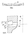
- the relief is shown as a rabbet 32 and in Figure 3 as a chamfer 34.
- This causes the rings when in operation other than under the influence of combustion firing loads to adopt a slightly dished formation and which is shown greatly exaggerated in Figure 4 as angle B.
- the dishing aids stability of the ring by reducing flutter and enhances the oil scraping ability of the angled working face.
- Figure 5 shows a modified form of lower open groove denoted generally at 40.
- the radial side face walls 42,44 of the groove as shown are angled in a downwardly direction relative to the piston axis 46, the angle C being negative between the groove and a normal to the axis 46.
- the angle C may however, be between ⁇ 1° and ⁇ 30° to a normal to the piston axis 46.
- the oil drain passage 52 may be a series of circumferentially extending slots or a series of holes around the piston groove periphery.
- the axis 48 of the slots or holes 52 may itself be at an angle to a normal to the piston axis 46 the angle being between ⁇ 1° and ⁇ 5°.
- Adjacent the lower radial face 44 is a chamfer 50 on the piston circumferential face.
- the chamfer may be replaced by a rabbet or any other form of suitable edge relief.
- the effect of the chamfer or rabbet 50 appears to be that it forms an expansion chamber allowing oil to be more easily swept into the groove 40 during descent of the piston in the cylinder bore.
- the form of open groove shown in Figure 5, in combination with piston rings as shown in Figures 1 to 4, provides a piston in accordance with the present invention.
Landscapes
- Engineering & Computer Science (AREA)
- General Engineering & Computer Science (AREA)
- Mechanical Engineering (AREA)
- Pistons, Piston Rings, And Cylinders (AREA)
Claims (3)
- Kolben für eine Brennkraftmaschine, der zwei Kolbenringe (18,20) mit jeweils einer Arbeitsfläche, die mit einer zugeordneten Zylinderwand (28) zusammenwirkt, und unter der untersten Kolbenringnut (14) sowie mit Abstand von dieser eine Leernut (40) mit zugehörigen Ölablaufkanälen (52) aufweist, dadurch gekennzeichnet, daß beide allgemein radial verlaufenden Seitenflächenwände (42,44) der Nut (40) mit einer Senkrechten auf die Kolbenachse (46) einen Winkel (C) im Bereich von +/- 1° bis +/- 30° ausbilden, und daß die Arbeitsfläche (24,26) zumindest des unteren Kolbenrings (20) einen Winkel (A) von wenigstens 1° 30′ mit der zugeordneten Zylinderwand (28) einschließt.
- Kolben nach Anspruch 1, dadurch gekennzeichnet, daß die Achsen (48) der Kanäle (52) mit einer Senkrechten zur Kolbenachse (46) einen Winkel im Bereich von +/- 1° bis +/- 5° einschließen.
- Kolben nach Anspruch 1 oder Anspruch 2, dadurch gekennzeichnet, daß die axial verlaufende Kolbenfläche in der Nähe der unteren radial verlaufenden Fläche (44) der Nut (40) über eine Schräge (50) oder eine Nut zurückgesetzt wird.
Applications Claiming Priority (2)
| Application Number | Priority Date | Filing Date | Title |
|---|---|---|---|
| IT8867987A IT1223887B (it) | 1988-11-04 | 1988-11-04 | Pistone e segmento per motori alternativi in genere |
| IT6798788 | 1988-11-04 |
Publications (2)
| Publication Number | Publication Date |
|---|---|
| EP0366983A1 EP0366983A1 (de) | 1990-05-09 |
| EP0366983B1 true EP0366983B1 (de) | 1993-12-22 |
Family
ID=11306969
Family Applications (1)
| Application Number | Title | Priority Date | Filing Date |
|---|---|---|---|
| EP89118892A Expired - Lifetime EP0366983B1 (de) | 1988-11-04 | 1989-10-11 | Kolben |
Country Status (5)
| Country | Link |
|---|---|
| EP (1) | EP0366983B1 (de) |
| JP (1) | JP2686328B2 (de) |
| DE (1) | DE68911652T2 (de) |
| GB (1) | GB2224555B (de) |
| IT (1) | IT1223887B (de) |
Cited By (1)
| Publication number | Priority date | Publication date | Assignee | Title |
|---|---|---|---|---|
| DE102021207405A1 (de) | 2021-07-13 | 2023-01-19 | Federal-Mogul Nürnberg GmbH | Stahlkolben für einen Verbrennungsmotor |
Families Citing this family (2)
| Publication number | Priority date | Publication date | Assignee | Title |
|---|---|---|---|---|
| DE102013216515A1 (de) * | 2013-08-21 | 2015-02-26 | Federal-Mogul Burscheid Gmbh | Ölabstreifring |
| US9470179B2 (en) * | 2014-06-06 | 2016-10-18 | General Electric Company | Piston assembly for a reciprocating engine |
Family Cites Families (12)
| Publication number | Priority date | Publication date | Assignee | Title |
|---|---|---|---|---|
| GB447220A (en) * | 1935-02-21 | 1936-05-14 | Hans Hendrik Blache | Improvements in and relating to piston rings or similar packing rings |
| GB484490A (en) * | 1936-11-05 | 1938-05-05 | Oswald Huntly | Improvements in and relating to piston rings for internal combustion engines |
| GB502695A (en) * | 1937-09-29 | 1939-03-23 | Vauxhall Motors Ltd | Improved piston rings for internal combustion engines |
| CH279038A (de) * | 1949-11-08 | 1951-11-15 | Goetzewerke | Kolben mit einem Ölabstreifring. |
| US3554568A (en) * | 1968-08-19 | 1971-01-12 | Dana Corp | Piston and piston ring combination |
| US3587155A (en) * | 1968-09-06 | 1971-06-28 | Int Harvester Co | Ring manufacture,productive of line contact seal |
| US3926166A (en) * | 1970-10-01 | 1975-12-16 | Int Harvester Co | Ring manufacture, productive of line contact seal |
| JPS582349U (ja) * | 1981-06-30 | 1983-01-08 | いすゞ自動車株式会社 | エンジン用ピストン |
| EP0069175A1 (de) * | 1981-07-03 | 1983-01-12 | Nissan Motor Co., Ltd. | Kolben für eine Brennkraftmaschine mit innerer Verbrennung |
| GB2104621A (en) * | 1981-08-14 | 1983-03-09 | Exxon Research Engineering Co | Piston ring lubrication |
| JPH0326292Y2 (de) * | 1984-09-10 | 1991-06-06 | ||
| JPH07109177B2 (ja) * | 1987-03-18 | 1995-11-22 | 株式会社リケン | 内燃機関 |
-
1988
- 1988-11-04 IT IT8867987A patent/IT1223887B/it active
-
1989
- 1989-10-11 EP EP89118892A patent/EP0366983B1/de not_active Expired - Lifetime
- 1989-10-11 DE DE68911652T patent/DE68911652T2/de not_active Expired - Fee Related
- 1989-10-12 GB GB8922999A patent/GB2224555B/en not_active Expired - Fee Related
- 1989-11-01 JP JP1283169A patent/JP2686328B2/ja not_active Expired - Lifetime
Cited By (3)
| Publication number | Priority date | Publication date | Assignee | Title |
|---|---|---|---|---|
| DE102021207405A1 (de) | 2021-07-13 | 2023-01-19 | Federal-Mogul Nürnberg GmbH | Stahlkolben für einen Verbrennungsmotor |
| WO2023285233A1 (de) | 2021-07-13 | 2023-01-19 | Federal-Mogul Nürnberg GmbH | Stahlkolben für einen verbrennungsmotor |
| US12584453B2 (en) | 2021-07-13 | 2026-03-24 | Federal-Mogul Nurnberg Gmbh | Steel piston for an internal combustion engine |
Also Published As
| Publication number | Publication date |
|---|---|
| JPH02176149A (ja) | 1990-07-09 |
| JP2686328B2 (ja) | 1997-12-08 |
| GB8922999D0 (en) | 1989-11-29 |
| IT1223887B (it) | 1990-09-29 |
| DE68911652T2 (de) | 1994-07-07 |
| IT8867987A0 (it) | 1988-11-04 |
| EP0366983A1 (de) | 1990-05-09 |
| DE68911652D1 (de) | 1994-02-03 |
| GB2224555B (en) | 1992-11-11 |
| GB2224555A (en) | 1990-05-09 |
Similar Documents
| Publication | Publication Date | Title |
|---|---|---|
| US5133563A (en) | Two ring piston with lower tapered L-shaped ring | |
| CA1239062A (en) | Piston and piston ring assemblies | |
| US20020085779A1 (en) | Half bearing with grooves preventing leakage of lubricating oil | |
| US2951732A (en) | Piston ring | |
| US6470792B1 (en) | Combined compression and oil scraper piston ring | |
| KR0170451B1 (ko) | 내연기관용 피스톤 상부 링 | |
| US1871820A (en) | Packing | |
| SE469346B (sv) | Cylinderlocks-foerbraenningsrumstaetning foer kolvmotorer | |
| EP0366983A1 (de) | Kolben | |
| US2173190A (en) | Piston ring | |
| US20020023609A1 (en) | Piston for a four-stroke internal combustion engine | |
| EP0251393B1 (de) | Kolben | |
| GB2143614A (en) | Expander spring for composite oil-ring | |
| US2372979A (en) | Piston ring | |
| GB2226097A (en) | A piston ring for an internal combustion engine | |
| US4041924A (en) | Reciprocating internal combustion engine | |
| US1584470A (en) | Internal-combustion-engine piston | |
| US3195903A (en) | Piston oil control ring | |
| US2638390A (en) | Piston and ring | |
| RU2283983C2 (ru) | Поршневой двигатель | |
| US5052698A (en) | Two-piece type oil ring assembly | |
| GB2161897A (en) | Preventing rotation of oil-control piston ring | |
| GB2104621A (en) | Piston ring lubrication | |
| SU1710807A1 (ru) | Поршневое компрессионное кольцо | |
| WO1988000289A1 (en) | Piston rings |
Legal Events
| Date | Code | Title | Description |
|---|---|---|---|
| PUAI | Public reference made under article 153(3) epc to a published international application that has entered the european phase |
Free format text: ORIGINAL CODE: 0009012 |
|
| AK | Designated contracting states |
Kind code of ref document: A1 Designated state(s): DE FR IT |
|
| 17P | Request for examination filed |
Effective date: 19900907 |
|
| 17Q | First examination report despatched |
Effective date: 19911002 |
|
| ITF | It: translation for a ep patent filed | ||
| GRAA | (expected) grant |
Free format text: ORIGINAL CODE: 0009210 |
|
| AK | Designated contracting states |
Kind code of ref document: B1 Designated state(s): DE FR IT |
|
| REF | Corresponds to: |
Ref document number: 68911652 Country of ref document: DE Date of ref document: 19940203 |
|
| ET | Fr: translation filed | ||
| PLBE | No opposition filed within time limit |
Free format text: ORIGINAL CODE: 0009261 |
|
| STAA | Information on the status of an ep patent application or granted ep patent |
Free format text: STATUS: NO OPPOSITION FILED WITHIN TIME LIMIT |
|
| 26N | No opposition filed | ||
| PGFP | Annual fee paid to national office [announced via postgrant information from national office to epo] |
Ref country code: FR Payment date: 20000911 Year of fee payment: 12 |
|
| PG25 | Lapsed in a contracting state [announced via postgrant information from national office to epo] |
Ref country code: FR Free format text: LAPSE BECAUSE OF NON-PAYMENT OF DUE FEES Effective date: 20020628 |
|
| REG | Reference to a national code |
Ref country code: FR Ref legal event code: ST |
|
| PGFP | Annual fee paid to national office [announced via postgrant information from national office to epo] |
Ref country code: DE Payment date: 20051031 Year of fee payment: 17 |
|
| PGFP | Annual fee paid to national office [announced via postgrant information from national office to epo] |
Ref country code: IT Payment date: 20061031 Year of fee payment: 18 |
|
| PG25 | Lapsed in a contracting state [announced via postgrant information from national office to epo] |
Ref country code: DE Free format text: LAPSE BECAUSE OF NON-PAYMENT OF DUE FEES Effective date: 20070501 |
|
| PG25 | Lapsed in a contracting state [announced via postgrant information from national office to epo] |
Ref country code: IT Free format text: LAPSE BECAUSE OF NON-PAYMENT OF DUE FEES Effective date: 20071011 |