EP0367035A1 - Presse ou poinçonneuse - Google Patents
Presse ou poinçonneuse Download PDFInfo
- Publication number
- EP0367035A1 EP0367035A1 EP89119435A EP89119435A EP0367035A1 EP 0367035 A1 EP0367035 A1 EP 0367035A1 EP 89119435 A EP89119435 A EP 89119435A EP 89119435 A EP89119435 A EP 89119435A EP 0367035 A1 EP0367035 A1 EP 0367035A1
- Authority
- EP
- European Patent Office
- Prior art keywords
- press
- pressure
- tool half
- tool
- plunger
- Prior art date
- Legal status (The legal status is an assumption and is not a legal conclusion. Google has not performed a legal analysis and makes no representation as to the accuracy of the status listed.)
- Granted
Links
- 238000004080 punching Methods 0.000 title abstract description 10
- 238000007654 immersion Methods 0.000 claims description 18
- 239000002184 metal Substances 0.000 claims description 4
- 230000001105 regulatory effect Effects 0.000 claims description 2
- 239000000463 material Substances 0.000 description 20
- 238000005520 cutting process Methods 0.000 description 13
- 238000004049 embossing Methods 0.000 description 12
- 238000011156 evaluation Methods 0.000 description 5
- 238000006073 displacement reaction Methods 0.000 description 4
- 230000001965 increasing effect Effects 0.000 description 4
- 230000001939 inductive effect Effects 0.000 description 3
- 230000035515 penetration Effects 0.000 description 3
- 238000009530 blood pressure measurement Methods 0.000 description 2
- 230000000694 effects Effects 0.000 description 2
- 238000010438 heat treatment Methods 0.000 description 2
- 238000005259 measurement Methods 0.000 description 2
- 229920006324 polyoxymethylene Polymers 0.000 description 2
- 238000011109 contamination Methods 0.000 description 1
- 230000002349 favourable effect Effects 0.000 description 1
- 230000007257 malfunction Effects 0.000 description 1
- 238000004519 manufacturing process Methods 0.000 description 1
- 238000000034 method Methods 0.000 description 1
- 230000033764 rhythmic process Effects 0.000 description 1
Images


Classifications
-
- B—PERFORMING OPERATIONS; TRANSPORTING
- B30—PRESSES
- B30B—PRESSES IN GENERAL
- B30B15/00—Details of, or accessories for, presses; Auxiliary measures in connection with pressing
- B30B15/0094—Press load monitoring means
-
- B—PERFORMING OPERATIONS; TRANSPORTING
- B30—PRESSES
- B30B—PRESSES IN GENERAL
- B30B15/00—Details of, or accessories for, presses; Auxiliary measures in connection with pressing
- B30B15/0029—Details of, or accessories for, presses; Auxiliary measures in connection with pressing means for adjusting the space between the press slide and the press table, i.e. the shut height
- B30B15/0041—Control arrangements therefor
Definitions
- the invention relates to a press or punch with a plunger carrying an upper tool half, the depth of which can be adjusted, and a press table arranged below the plunger and carrying the associated lower tool half and with a control device having at least one measuring sensor arranged on the tool for adjusting the Immersion depth of the ram when the press or punch is in operation.
- Adjusting the plunger depth during operation is desirable because the plunger depth changes with the heating of the press or punch and the tool. This change in plunger depth can have a negative impact on the quality of the machined workpieces.
- a ram adjustment is known, which makes it possible with high-speed cutting presses that the depth of immersion of an upper tool in an associated lower tool also with increasing working speed, i.e. higher stroke rate, can be kept constant.
- an inductive displacement transducer is arranged between the tools, with which the immersion depth is recorded directly and passed on to the control device. The ram height is readjusted by a setpoint / actual value comparison.
- a disadvantage of the known press is that the ram adjustment does not take fluctuating material thicknesses into account, at least when using embossing tools. But even if the tool halves are regrinded after a certain amount of wear, the specified nominal value of the immersion depth is no longer correct, so that complex readjustments are necessary. Otherwise, the inductive displacement sensor sensitive to pollution, heating and external influences, which can lead to malfunctions.
- the senor is designed as a pressure sensor and, opposite the underside of the upper tool half, is arranged on the upper side or, opposite the upper side of the press table, on the underside of the lower tool half.
- the plunger depth is no longer controlled directly, but indirectly via the tool pressure.
- the measuring sensor is expediently arranged on the upper side of the lower half of the tool, so that it interacts with the underside of the upper half of the tool.
- the pressure acting on the pressure transducer when the two tool halves are moved together is a measure of the immersion depth of the cutting punch of the upper tool half in the die of the lower tool half. This pressure measurement, which only indirectly reflects the immersion depth, allows the tool load to be read off directly and the ram immersion depth to be increased for blunt tools.
- the pressure transducer is significantly less susceptible to wear than the known contactless inductive displacement transducers and less sensitive to contamination, since there is no relative movement of two parts against one another, in which frictional forces could act.
- the immersion depth of the embossing die of the upper tool half in the die of the lower tool half is not so important; it is rather the aim to always keep the surface of the workpiece looking the same.
- the pressure sensor is now arranged on the underside of the lower half of the tool and interacts with the top of the press table, the pressure that the stamping die exerts on the material is measured. This pressure is a measure of the depth of penetration of the die into the material, which must be distinguished from the depth of immersion of the die into the die.
- the invention is based on the finding that a constant work result can only be achieved by moving away from the displacement measurement and by using the pressure measurement, both for punched and embossed workpieces.
- the pressure sensor is formed from a pressure-resilient base body, in which a piezo element connected to the control device is embedded and the end of which is facing the top or the bottom of the lower tool half is covered with a rigid pressure plate. Since the piezo element is embedded in the elastically resilient base body, the pressure received by the pressure plate when the two tool halves are moved together is passed on uniformly to the piezo element, so that this pressure sensor is particularly insusceptible to faults.
- the pressure body from a plastic, preferably a polyformaldehyde.
- the pressure plate can be made of metal, preferably the same material as the tool.
- the pressure sensor is embedded in the lower half of the tool. Particularly good results can be achieved with punching tools if the pressure plate of the pressure transducer lies on the top of the lower half of the tool and is flush with the top of the lower half of the tool. As a result, the pressure plate of the pressure transducer is also ground to the same extent when regrinding the cutting punch, so that regrinding the tools has no influence on the measurements.
- the pressure transducer which is preferably provided for punching tools, the two tool halves are moved together during punching, the pressure between the two tool halves being measured directly, and not via the cutting punch, the material and the die. This means that with a thicker material where the cutting pressure is higher, a lower pressure is initially measured between the two tool halves, so that the material thickness during punching has no effect on the depth of the plunger and thus the work result.
- the base body of the pressure transducer can also be conveniently embedded in the press table.
- the pressure plate of the pressure sensor is then on the underside of the lower half of the tool. In this way, the pressure exerted by the stamp on the material and thus on the lower half of the tool is recorded. Even with different material thicknesses, this arrangement of the pressure sensor always ensures that the depth of penetration of the die into the material is always the same, so that here too the material thickness has no influence on the work result.
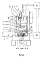
- All machines have a height-adjustable ram 1 and a press table 2 arranged underneath.
- the tappet 1 is connected to two connecting rods 3 which are mounted in a crankshaft 4 arranged in the upper part of the machine.
- the plunger 1 is adjustable in height with respect to the connecting rods 3, which is known per se.
- a known adjusting mechanism 5 is provided, which is connected to a servo motor 7 via a spline shaft 6.
- the spline 6 enables the servo motor 7 to be fixed in place while the spline can move with the stroke of the ram.
- the ram By actuating the servo motor 7, the ram can be raised or lowered relative to the connecting rods 3 via the adjusting gear 5. The stroke is not adjusted, but rather the effective connecting rod length.
- An upper tool half 8 is arranged on the underside of the ram 1, while a lower tool half 9 is arranged on the upper side of the press table 2.
- a feed device 10 is arranged to the side of the tools, with which sheet metal strips are intermittently passed between the tool halves.
- a pressure sensor 11 is provided in the area of the tool halves 8 and 9.
- the pressure sensor 11 consists of a base body 12 made of polyformaldehyde, in which a piezo element 13 is embedded.
- the base body 12 is covered by a metal pressure plate 14.
- the piezo element 13 is connected to an evaluation device 15, which forwards to a converter which transmits the pressure signal received by the piezo element, depending on whether the measured pressure is higher or lower than a predetermined target value.
- the converter 16 sends a signal to an angle encoder 17 of the servo motor 7, so that the ram height is adjusted via the servo motor and the angle gear, and the depth of the plunger is thereby regulated.
- the base body 12 of the pressure transducer 11 is let into the lower tool half 9 and in such a way that the pressure plate 14 of the pressure transducer is arranged flush with the upper side 18 of the lower tool half 9.
- the pressure transducer 11 is installed in the lower tool half 9 before the lower tool half is ground flat on its upper side. From Fig. 1 it can be clearly seen that 9 individual punches 19 are arranged on the underside of the upper tool.
- a pressure piece 20 is provided, which lies exactly above the pressure plate 14 of the pressure sensor 11.
- This arrangement of the pressure transducer 11 is particularly suitable when the tool halves 8 and 9 are provided for punching out workpieces, ie when they are provided with cutting dies 19 are. Then it depends on the fact that regardless of any machine or material conditions, the depth of immersion of the punch 19 in the associated matrices of the lower tool half 9 is always the same so that the workpieces are cut out. When the punch is heated, however, components such as the connecting rods 3 and the plunger 1 expand, so that the immersion depth of the cutting punches 19 would change if the plunger immersion depth were not readjusted. In the arrangement shown in FIG. 1, the pressure between the two tool halves is therefore measured, which is measured on the tool halves 8 and 9 during the cutting outside the cutting punches 19.
- the evaluation device 15 which carries out a corresponding setpoint / actual value comparison, effects a corresponding actuation of the servo motor 7 via the converter 16 and the angle encoder 17, which then reduces the immersion depth of the plunger 1 via the adjustment gear 5.
- the plunger immersion depth is increased in an analogous manner.
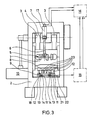
- the second exemplary embodiment of a press according to the invention shown in FIG. 3 differs from the previously described exemplary embodiment essentially in that two pressure transducers 11 are provided which are embedded in the lower tool half 9 in such a way that their pressure plate 14 is flush with the underside 21 of the lower one Tool half 9 completes and touches the top 22 of the press table 2.
- the tool halves 8 and 9 are an embossing tool; Embossing dies 23 are accordingly provided in the upper tool half 8.
- the plunger 1 moves up and down in the rhythm of the crankshaft 4, the dies 23 press on the material, not shown here, guided by the feed device 10 between the tool halves 8 and 9.
- the pressure exerted is from measured the two pressure transducers 11 and signaled to the evaluation device 15. If, when the press heats up, the pressure measured by the pressure transducers 11 increases during the operation of the press, the evaluation device 15 sends a signal to the servo motor 7 via the converter 16 and the angle encoder 17, whereupon the latter reduces the immersion depth of the plunger 1 via the adjustment gear 5 To the extent that the actual pressure continuously measured by the pressure sensor 11 corresponds to the predetermined target pressure.
- the depth of the plunger 1 is increased in an analogous manner. This ensures that the dies 23 always penetrate the material with the same pressure, so that all the stampings produced with the press have the same appearance, regardless of any material fluctuations, since these material fluctuations also increase or decrease the result in pressure measured by the pressure transducers and thus cause an adjustment of the plunger immersion depth.
- FIG. 4 shows a third exemplary embodiment in which the base body 12 of the pressure sensor 11 is let into the press table 2, so that the pressure plate 14 lies on the upper side 22 of the press table 2 and touches the lower side 21 of the lower tool half 9.
- the tool halves 8 and 9 are also designed as embossing tools. The operation of this press corresponds to the press shown in Fig. 3, but both tool halves 8 and 9 can be exchanged for another tool without the pressure sensor 11 having to be replaced. If the press is to be converted, it is therefore only necessary to specify a new pressure setpoint for the evaluation device 15.
- FIGS. 3 and 4 are described using embossing tools and the exemplary embodiment according to FIGS. 1 and 2 using a cutting tool, it is also conceivable to use cutting tools in the presses according to FIGS. 3 and 4 and in the press according to FIG. 1 and 2 to use an embossing tool or a combination of cutting and embossing tool.
- the pressure body prefferably be made of a material other than plastic, e.g. As rubber, to manufacture, a material of high elasticity is preferred, the tensile strength is 50-70 N / cm2.
Landscapes
- Engineering & Computer Science (AREA)
- Mechanical Engineering (AREA)
- Presses And Accessory Devices Thereof (AREA)
- Perforating, Stamping-Out Or Severing By Means Other Than Cutting (AREA)
- Control Of Presses (AREA)
- Punching Or Piercing (AREA)
- Polishing Bodies And Polishing Tools (AREA)
Priority Applications (1)
| Application Number | Priority Date | Filing Date | Title |
|---|---|---|---|
| AT89119435T ATE79801T1 (de) | 1988-11-03 | 1989-10-19 | Presse oder stanze. |
Applications Claiming Priority (2)
| Application Number | Priority Date | Filing Date | Title |
|---|---|---|---|
| DE8813774U | 1988-11-03 | ||
| DE8813774U DE8813774U1 (de) | 1988-11-03 | 1988-11-03 | Presse oder Stanze |
Publications (2)
| Publication Number | Publication Date |
|---|---|
| EP0367035A1 true EP0367035A1 (fr) | 1990-05-09 |
| EP0367035B1 EP0367035B1 (fr) | 1992-08-26 |
Family
ID=6829508
Family Applications (1)
| Application Number | Title | Priority Date | Filing Date |
|---|---|---|---|
| EP89119435A Expired - Lifetime EP0367035B1 (fr) | 1988-11-03 | 1989-10-19 | Presse ou poinçonneuse |
Country Status (4)
| Country | Link |
|---|---|
| EP (1) | EP0367035B1 (fr) |
| AT (1) | ATE79801T1 (fr) |
| DD (1) | DD285951A5 (fr) |
| DE (2) | DE8813774U1 (fr) |
Cited By (10)
| Publication number | Priority date | Publication date | Assignee | Title |
|---|---|---|---|---|
| WO1992002361A1 (fr) * | 1990-08-07 | 1992-02-20 | O & K Geissler Gmbh | Machine-outil travaillant des metaux par formage et par coupage ayant un dispositif d'ajustage situe dans une partie mobile de la machine |
| EP0554501A1 (fr) * | 1991-06-28 | 1993-08-11 | Aida Engineering Ltd. | Dispositif de correction de la position du point mort inférieur d'une presse |
| US5379688A (en) * | 1991-12-03 | 1995-01-10 | Ishii; Mitishi | Method of and apparatus for automatically controlling pressing force of press machine |
| EP0741001A3 (fr) * | 1995-05-04 | 1997-02-26 | Gietz Ag | Estampeuse, imprimeuse et poinçonneuse |
| EP1177885A1 (fr) * | 2000-08-01 | 2002-02-06 | Haulick + Roos GmbH | Machine automatique pour le pressage ou l'estampage |
| EP1308268A1 (fr) * | 2001-11-06 | 2003-05-07 | Haulick + Roos GmbH | Machine automatique pour le pressage ou l'estampage |
| EP1533109A3 (fr) * | 2003-11-12 | 2007-12-12 | Tom Engmann | Poinçon de presse pour la fabrication des ébauches de carreaux en céramique et presse équipée de ce poinçon |
| DE102008011375A1 (de) * | 2008-02-27 | 2009-09-10 | A. Schaal Gmbh & Co. Werkzeug- Und Maschinenbau | Antriebseinrichtung für eine Presse |
| DE102007062458A1 (de) * | 2007-12-22 | 2009-09-10 | A. Schaal Gmbh & Co. Werkzeug- Und Maschinenbau | Antriebseinrichtung für eine Presse |
| WO2020015815A1 (fr) * | 2018-07-16 | 2020-01-23 | Bruderer Ag | Procédé de fonctionnement d'une poinçonneuse et poinçonneuse pour le fonctionnement selon ce procédé |
Families Citing this family (1)
| Publication number | Priority date | Publication date | Assignee | Title |
|---|---|---|---|---|
| DE102015211622A1 (de) | 2015-06-23 | 2016-12-29 | Multivac Sepp Haggenmüller Se & Co. Kg | Tiefziehverpackungsmaschine mit Folienstanze |
Citations (6)
| Publication number | Priority date | Publication date | Assignee | Title |
|---|---|---|---|---|
| US4010679A (en) * | 1967-09-25 | 1977-03-08 | International Measurement & Control Co. | Piezoelectric transducer sensor for use in a press |
| DE2814988A1 (de) * | 1978-04-07 | 1979-10-11 | Klaus Brankamp System Prozessa | Verfahren zur messung und/oder zur fuer eine steuerung auswertbaren darstellung einer kraft |
| DE2833829A1 (de) * | 1978-08-02 | 1980-02-21 | Schuler Gmbh L | Schaltungsanordnung fuer einen stellantrieb einer stoesselverstellung |
| EP0145001A2 (fr) * | 1983-12-12 | 1985-06-19 | Pfister GmbH | Dispositif de mesure de force |
| DE3439459A1 (de) * | 1983-12-29 | 1985-07-11 | Fukui Machinery Co., Ltd., Fukui | Vorrichtung zur automatischen korrektur der position eines schlittens in einer presse |
| JPS63180400A (ja) * | 1987-01-23 | 1988-07-25 | Nkk Corp | プレス機の自動荷重制御装置 |
-
1988
- 1988-11-03 DE DE8813774U patent/DE8813774U1/de not_active Expired - Lifetime
-
1989
- 1989-10-19 EP EP89119435A patent/EP0367035B1/fr not_active Expired - Lifetime
- 1989-10-19 AT AT89119435T patent/ATE79801T1/de not_active IP Right Cessation
- 1989-10-19 DE DE8989119435T patent/DE58902145D1/de not_active Expired - Fee Related
- 1989-11-02 DD DD89334165A patent/DD285951A5/de not_active IP Right Cessation
Patent Citations (6)
| Publication number | Priority date | Publication date | Assignee | Title |
|---|---|---|---|---|
| US4010679A (en) * | 1967-09-25 | 1977-03-08 | International Measurement & Control Co. | Piezoelectric transducer sensor for use in a press |
| DE2814988A1 (de) * | 1978-04-07 | 1979-10-11 | Klaus Brankamp System Prozessa | Verfahren zur messung und/oder zur fuer eine steuerung auswertbaren darstellung einer kraft |
| DE2833829A1 (de) * | 1978-08-02 | 1980-02-21 | Schuler Gmbh L | Schaltungsanordnung fuer einen stellantrieb einer stoesselverstellung |
| EP0145001A2 (fr) * | 1983-12-12 | 1985-06-19 | Pfister GmbH | Dispositif de mesure de force |
| DE3439459A1 (de) * | 1983-12-29 | 1985-07-11 | Fukui Machinery Co., Ltd., Fukui | Vorrichtung zur automatischen korrektur der position eines schlittens in einer presse |
| JPS63180400A (ja) * | 1987-01-23 | 1988-07-25 | Nkk Corp | プレス機の自動荷重制御装置 |
Cited By (14)
| Publication number | Priority date | Publication date | Assignee | Title |
|---|---|---|---|---|
| WO1992002361A1 (fr) * | 1990-08-07 | 1992-02-20 | O & K Geissler Gmbh | Machine-outil travaillant des metaux par formage et par coupage ayant un dispositif d'ajustage situe dans une partie mobile de la machine |
| US5381681A (en) * | 1990-08-07 | 1995-01-17 | O & K Geissler Gmbh | Machine with an adjusting device located in a movable machine part |
| EP0554501A1 (fr) * | 1991-06-28 | 1993-08-11 | Aida Engineering Ltd. | Dispositif de correction de la position du point mort inférieur d'une presse |
| US5379688A (en) * | 1991-12-03 | 1995-01-10 | Ishii; Mitishi | Method of and apparatus for automatically controlling pressing force of press machine |
| EP0741001A3 (fr) * | 1995-05-04 | 1997-02-26 | Gietz Ag | Estampeuse, imprimeuse et poinçonneuse |
| US5746122A (en) * | 1995-05-04 | 1998-05-05 | Maschinenfabrik Gietz Ag | Embossing machine |
| EP1177885A1 (fr) * | 2000-08-01 | 2002-02-06 | Haulick + Roos GmbH | Machine automatique pour le pressage ou l'estampage |
| EP1308268A1 (fr) * | 2001-11-06 | 2003-05-07 | Haulick + Roos GmbH | Machine automatique pour le pressage ou l'estampage |
| EP1533109A3 (fr) * | 2003-11-12 | 2007-12-12 | Tom Engmann | Poinçon de presse pour la fabrication des ébauches de carreaux en céramique et presse équipée de ce poinçon |
| DE102007062458A1 (de) * | 2007-12-22 | 2009-09-10 | A. Schaal Gmbh & Co. Werkzeug- Und Maschinenbau | Antriebseinrichtung für eine Presse |
| DE102007062458B4 (de) * | 2007-12-22 | 2011-05-19 | Schaal Engineering Gmbh | Antriebseinrichtung für eine Presse |
| DE102008011375A1 (de) * | 2008-02-27 | 2009-09-10 | A. Schaal Gmbh & Co. Werkzeug- Und Maschinenbau | Antriebseinrichtung für eine Presse |
| DE102008011375B4 (de) * | 2008-02-27 | 2010-06-02 | A. Schaal Gmbh & Co. Werkzeug- Und Maschinenbau | Antriebseinrichtung für eine Presse |
| WO2020015815A1 (fr) * | 2018-07-16 | 2020-01-23 | Bruderer Ag | Procédé de fonctionnement d'une poinçonneuse et poinçonneuse pour le fonctionnement selon ce procédé |
Also Published As
| Publication number | Publication date |
|---|---|
| DE58902145D1 (de) | 1992-10-01 |
| ATE79801T1 (de) | 1992-09-15 |
| EP0367035B1 (fr) | 1992-08-26 |
| DD285951A5 (de) | 1991-01-10 |
| DE8813774U1 (de) | 1990-03-01 |
Similar Documents
| Publication | Publication Date | Title |
|---|---|---|
| DE69833396T2 (de) | Hydraulische Presse zur Herstellung von Metallplatten | |
| DE3840395C2 (de) | Steuerung einer Blechbearbeitungspresse | |
| DE3739029C2 (de) | Stanz- bzw. Nibbelverfahren und Vorrichtung hierfür | |
| DE3823258A1 (de) | Maschine zur ausbildung einer v-foermigen aussparung und verfahren zur steuerung derselben | |
| EP0873855B1 (fr) | Procédé et dispositif pour la fabrication pièces moulées en métal dur, céramique, métal fritté ou similaire | |
| DE69106601T2 (de) | Vorrichtung und System zum Stanzen von gedruckten Schaltplatten. | |
| DE3703674A1 (de) | Verfahren zur hubsteuerung einer blechbearbeitungsmaschine | |
| DE3623035C1 (de) | Verfahren und Vorrichtung zum Herstellen eines eine scharfe Schneidkante aufweisenden Stanzwerkzeugs | |
| DE69936407T2 (de) | Verfahren zur Werkzeugeinstellung in einer Blechherstellungsmaschine | |
| EP0367035B1 (fr) | Presse ou poinçonneuse | |
| EP0418779A1 (fr) | Méthode pour manufacture de pièces d'oeuvre par découpage, en particulier dans un outil à contre découpage à précision | |
| DE3153332C2 (de) | Verfahren zur Steuerung einer hydraulischen Presse zum Pressen von Platten auf Holzbasis und Vorrichtung zur Durchführung des Verfahrens | |
| EP2092991B1 (fr) | Matrice à plier pour une presse à plier, notamment presse plieuse et procédé de pliage d'une pièce | |
| DE2731084C3 (de) | Stößelverstellung für schnellaufende Schnittpressen | |
| DE3346282A1 (de) | Vorrichtung zum bestimmen einer endstellung des stoessels einer presse | |
| DE3040762C2 (de) | Verfahren und Vorrichtung zur Einstellung der Masse von Posten thermoplastischen Materials | |
| EP0353479B1 (fr) | Procédé et dispositif pour réduire la charge de presse dans une presse à découper comportant des butées fixes | |
| DE2937176A1 (de) | Bandsaegemaschine | |
| DE102006031438B4 (de) | Vorrichtung zum Umformen von Platinen | |
| DE68921102T2 (de) | Antriebssystem für Schreibgerät in einer Zeichenmaschine oder dergleichen. | |
| EP0732194A1 (fr) | Procédé et dispositif de mesure et de réglage de la position du coulisseau d'une presse à découper à grande vitesse | |
| DE3028834C2 (fr) | ||
| EP1287975B1 (fr) | Procédé pour la production d'éléments moulés dans une presse à poudre | |
| EP0428780B1 (fr) | Presse à poinçonner avec entrée de valeur de correction pour la profondeur de pénétration et la longueur d'alimentation | |
| DE3136753C2 (de) | Tiefzieheinrichtung für Platine |
Legal Events
| Date | Code | Title | Description |
|---|---|---|---|
| PUAI | Public reference made under article 153(3) epc to a published international application that has entered the european phase |
Free format text: ORIGINAL CODE: 0009012 |
|
| AK | Designated contracting states |
Kind code of ref document: A1 Designated state(s): AT CH DE FR IT LI |
|
| 17P | Request for examination filed |
Effective date: 19900410 |
|
| 17Q | First examination report despatched |
Effective date: 19911023 |
|
| GRAA | (expected) grant |
Free format text: ORIGINAL CODE: 0009210 |
|
| AK | Designated contracting states |
Kind code of ref document: B1 Designated state(s): AT CH DE FR IT LI |
|
| REF | Corresponds to: |
Ref document number: 79801 Country of ref document: AT Date of ref document: 19920915 Kind code of ref document: T |
|
| REF | Corresponds to: |
Ref document number: 58902145 Country of ref document: DE Date of ref document: 19921001 |
|
| ET | Fr: translation filed | ||
| ITF | It: translation for a ep patent filed | ||
| PLBE | No opposition filed within time limit |
Free format text: ORIGINAL CODE: 0009261 |
|
| STAA | Information on the status of an ep patent application or granted ep patent |
Free format text: STATUS: NO OPPOSITION FILED WITHIN TIME LIMIT |
|
| 26N | No opposition filed | ||
| REG | Reference to a national code |
Ref country code: CH Ref legal event code: PUE Owner name: ANDRITZ TECHNOLOGY AND ASSET MANAGEMENT GMBH Free format text: OTTO KAISER GMBH#GEWERBESTRASSE 30#75015 BRETTEN (DE) -TRANSFER TO- ANDRITZ TECHNOLOGY AND ASSET MANAGEMENT GMBH#STATTEGGER STRASSE 18#8045 GRAZ (AT) Ref country code: CH Ref legal event code: PFA Owner name: OTTO KAISER GMBH Free format text: OTTO KAISER GMBH & CO. KG#GEWERBESTRASSE 30#BRETTEN (DE) -TRANSFER TO- OTTO KAISER GMBH#GEWERBESTRASSE 30#75015 BRETTEN (DE) Ref country code: CH Ref legal event code: NV Representative=s name: ISLER & PEDRAZZINI AG |
|
| PGFP | Annual fee paid to national office [announced via postgrant information from national office to epo] |
Ref country code: FR Payment date: 20051014 Year of fee payment: 17 Ref country code: DE Payment date: 20051014 Year of fee payment: 17 Ref country code: CH Payment date: 20051014 Year of fee payment: 17 |
|
| PGFP | Annual fee paid to national office [announced via postgrant information from national office to epo] |
Ref country code: AT Payment date: 20051017 Year of fee payment: 17 |
|
| REG | Reference to a national code |
Ref country code: FR Ref legal event code: TP Ref country code: FR Ref legal event code: CJ Ref country code: FR Ref legal event code: CD |
|
| PG25 | Lapsed in a contracting state [announced via postgrant information from national office to epo] |
Ref country code: AT Free format text: LAPSE BECAUSE OF NON-PAYMENT OF DUE FEES Effective date: 20061019 |
|
| PG25 | Lapsed in a contracting state [announced via postgrant information from national office to epo] |
Ref country code: LI Free format text: LAPSE BECAUSE OF NON-PAYMENT OF DUE FEES Effective date: 20061031 Ref country code: CH Free format text: LAPSE BECAUSE OF NON-PAYMENT OF DUE FEES Effective date: 20061031 |
|
| PGFP | Annual fee paid to national office [announced via postgrant information from national office to epo] |
Ref country code: IT Payment date: 20061031 Year of fee payment: 18 |
|
| PG25 | Lapsed in a contracting state [announced via postgrant information from national office to epo] |
Ref country code: DE Free format text: LAPSE BECAUSE OF NON-PAYMENT OF DUE FEES Effective date: 20070501 |
|
| REG | Reference to a national code |
Ref country code: CH Ref legal event code: PL |
|
| REG | Reference to a national code |
Ref country code: FR Ref legal event code: ST Effective date: 20070629 |
|
| PG25 | Lapsed in a contracting state [announced via postgrant information from national office to epo] |
Ref country code: FR Free format text: LAPSE BECAUSE OF NON-PAYMENT OF DUE FEES Effective date: 20061031 |
|
| PG25 | Lapsed in a contracting state [announced via postgrant information from national office to epo] |
Ref country code: IT Free format text: LAPSE BECAUSE OF NON-PAYMENT OF DUE FEES Effective date: 20071019 |