EP0367225B1 - Scheibenantenne für Kraftfahrzeuge - Google Patents
Scheibenantenne für Kraftfahrzeuge Download PDFInfo
- Publication number
- EP0367225B1 EP0367225B1 EP89120192A EP89120192A EP0367225B1 EP 0367225 B1 EP0367225 B1 EP 0367225B1 EP 89120192 A EP89120192 A EP 89120192A EP 89120192 A EP89120192 A EP 89120192A EP 0367225 B1 EP0367225 B1 EP 0367225B1
- Authority
- EP
- European Patent Office
- Prior art keywords
- antenna
- power supply
- glass window
- heating conductor
- capacitor
- Prior art date
- Legal status (The legal status is an assumption and is not a legal conclusion. Google has not performed a legal analysis and makes no representation as to the accuracy of the status listed.)
- Expired - Lifetime
Links
- 239000011521 glass Substances 0.000 title claims description 38
- 238000010438 heat treatment Methods 0.000 claims description 51
- 239000004020 conductor Substances 0.000 claims description 49
- 239000003990 capacitor Substances 0.000 claims description 33
- 230000008878 coupling Effects 0.000 claims description 9
- 238000010168 coupling process Methods 0.000 claims description 9
- 238000005859 coupling reaction Methods 0.000 claims description 9
- 230000035945 sensitivity Effects 0.000 description 37
- 239000005357 flat glass Substances 0.000 description 7
- 230000008859 change Effects 0.000 description 2
- 230000003247 decreasing effect Effects 0.000 description 2
- 230000004048 modification Effects 0.000 description 2
- 238000012986 modification Methods 0.000 description 2
- 239000006096 absorbing agent Substances 0.000 description 1
- 239000005391 art glass Substances 0.000 description 1
- 230000000593 degrading effect Effects 0.000 description 1
- 238000010586 diagram Methods 0.000 description 1
- 230000004907 flux Effects 0.000 description 1
- 230000006872 improvement Effects 0.000 description 1
- 239000000463 material Substances 0.000 description 1
- 230000003071 parasitic effect Effects 0.000 description 1
- 230000001902 propagating effect Effects 0.000 description 1
- 230000004044 response Effects 0.000 description 1
- 239000007787 solid Substances 0.000 description 1
Images


Classifications
-
- H—ELECTRICITY
- H01—ELECTRIC ELEMENTS
- H01Q—ANTENNAS, i.e. RADIO AERIALS
- H01Q1/00—Details of, or arrangements associated with, antennas
- H01Q1/12—Supports; Mounting means
- H01Q1/1271—Supports; Mounting means for mounting on windscreens
- H01Q1/1278—Supports; Mounting means for mounting on windscreens in association with heating wires or layers
Definitions
- the present invention relates to window glass antennas for motor vehicles and, more particularly to an antenna arrangement in which a defogging heater conductor formed on a window glass of a motor vehicle serves as an antenna for receiving radio signals.
- An antenna arrangement of this kind is known in the art.
- a leakage of the received signals to a direct current (DC) heater power supply or ground must be minimized.
- DC direct current
- the heating conductor antenna covers an FM broadcasting band only, choke coils having a relatively small inductance will suffice. However, such small coils will considerably decrease their impedance of radio signal leakage for an AM broadcasting band, thus reducing available antenna power in AM band.
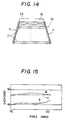
- Fig. 1 shows an example of the prior art window glass antenna of this type.
- the antenna is arranged such that a large number of heater wires or strip conductors 2 constituting a defogging heater conductor 10 and serving as an AM antenna are formed in a defogging area of a rear glass window 1.
- the heater wires are subdivided into upper and lower wire groups which are powered from power supply buses 3 and 4 connected to first ends of the upper and lower wire groups, respectively.
- a connecting bus 5 is disposed along and commonly connects second or remote ends of the upper and lower wire groups to complete a heating current path. Since the heater wires 2 are used as an AM broadcast band reception antenna, a feeder cable 13 such as a coaxial cable is connected to a feeding point 12 provided in the connecting bus 5.
- the feeder cable 13 carries the received signal to an AM radio tuner mounted in the motor vehicle through a DC cut capacitor 14.
- a separate FM antenna 6 is formed in a blank portion of the window 1 above the heater wires 2. It comprises a main antenna element 6a in the form of two parallel wires connected to each other in a substantial U shape, an auxiliary antenna element 6b disposed above and connected to the upper wire of the main antenna element 6a, another auxiliary antenna element 6c connected to the lower wire of the main antenna element 6a and facing the heater wires 2, and a folded element 6d bent back from the upper wire of the main antenna element and having a portion adjacent to the auxiliary antenna 6b.
- a feeding point 7 is formed on the folded portion 6d and connected to a feeder cable 8 for supplying an FM reception signal to an FM radio tuner through a DC cut capacitor 9.
- a main DC power supply feeds a heating current to the power supply buses 3 and 4 through choke coils 16a and 16b magnetically coupled to each other.
- the choke coil 16a connected to a main power +B is negatively coupled to the choke coil 16b connected to a ground so that magnetic fluxes generated by the respective heating currents cancel each other within a core. Therefore, the core having a small volume can be operated in a nonsaturated state.
- a decoupling capacitor 20 is connected between a ground and a line connected to the main power +B to prevent power source noise from being superposed on the reception signal.
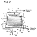
- Fig. 2 illustrates another example of the prior art window glass antenna arrangement.
- Figs. 1 and 2 like references refer to like parts.
- the top FM antenna 36 includes a coupling element 37 along the uppermost heating wire 2 for coupling with the heater conductor 10, and a feeding pad 7 connected to a feeder cable 35 for carrying AM and FM signals to an AM/FM tuner.
- the bottom FM antenna 38 also includes a coupling element 39 along the lowermost heating wire for coupling with signals from the heater conductor 10 and a feeding pad 40 connected to another feeder cable 41 for supplying the AM/FM tuner with AM and FM signals received in the heater conductor 10 and the bottom FM antenna conductor 38.
- the prior art requires a separate antenna element or elements for receiving FM band signals in addition to the heater conductor because the heater conductor only serves as an AM antenna.
- Such separate antenna element thus requires a relatively wide space for its mounting, as wide as about 120 to 150 mm above and/or below the heater conductor. Therefore, the prior art antenna arrangement is applicable only to a vehicle window glass having a large space; in small-sized cars such as two-box car, the rear window glass is limited in size, and further limited when it is mounted relatively up-right in the vehicle so that there is only a small top or bottom margin left in available for mounting an FM antenna conductor, once the heating conductor is formed on such small vehicle window.
- a glass window antenna having the features of the preamble of appended claim 1 is described in the document FR-A-2 250 329. It comprises a first antenna element connected to the upper end of a vertical power supply bus, and a second antenna element connected to the lower end of the same bus.
- the glass window antenna of this invention is defined by claim 1.
- a first and a second antenna element are connected to different power supply bus means.
- a third antenna element extends between said first and second antenna elements.
- the additional antenna element may be regarded as a coupling means for coupling the first and second antenna elements with each other with respect to signals generated or carried therein.
- the glass window antenna additionally comprises a choke coil in each power supply line, and a capacitive circuit connected to said power supply lines at a position between the choke coils and the power supply bus means.
- the combination of the capacitive circuit and the choke coils serves as an optimal impedance element which effectively prevents the radio signals received in the heating conductor means from passing or leaking through the choke coils while allowing passing the heating current to the heating conductor means through the choke coils and the power supply means.
- the capacitive circuit serves to vary or adjust the effective length of the antenna because it is connected across the pair of power supply lines that are connected to the heating conductor receiving radio waves.
- the choke coils may have a relatively high impedance for a first band of frequencies (e. g. AM broadcasting band) and a relatively low impedance for a second band of frequencies (e. g. FM broadcasting bands), in which the frequencies are higher by at least one order of magnitude than in the first band.
- a first band of frequencies e. g. AM broadcasting band
- a second band of frequencies e. g. FM broadcasting bands
- FIG. 3 there is shown a front view of a rear glass window for a motor vehicle mounting a radio receiving antenna function in conjunction with associated circutry shown in a schematic diagram in accordance with an embodiment of the invention.
- a heating conductor 10 is arranged in a defogging area of a rear glass window 1. When a heating current is supplied to the heating conductor 10, it is heated to defog the glass surface.
- a pair of antenna elements 23 and 24 is formed on a top margin of the glass window 1 and bears a symmetrical relationship with each other with respect to a central axis of the heating conductor 10.
- the left-hand antenna elements 23 has a left and connected to the upper end of the power supply bus 3 of the heating conductor 10 while the right-hand antenna element 24 has a right end connected to the upper end of the power supply bus 4 of the heating conductor 10.
- These antenna elements 23, 24 are parallel to the uppermost heater wire 2 and spaced therefrom by an interval of 31 mm.
- the antenna elements having free ends will change a state of a radio wave propagating on the heating conductor 10. Therefore, an appropriate choice of the dimensions of the antenna elements will optimize antenna reception sensitivity of the heating conductor 10 to an FM broadcasting band
- a feed point or pad 11 is provided in the heating conductor 10, here, at the bottom of the right-hand power supply bus 4.
- the feed pad 11 gathers radio signals covering at least AM and FM broadcasting bands, as received in the heating conductor 10 and the symmetrical antenna elements 23 to 25.
- a feeder cable 22 is in the form of a coaxial cable is connected to the feeder pad 11 via a capacitor 21 to carry the signals to radio receiving circuitry such as AM and FM tuners (not shown).
- Choke coils 16a and 16b are respectively inserted into power supply lines 17 and 18.
- the choke coils are magnetically coupled with each other in a nonsaturated state.
- the opposite end of the choke coil 16a from the heater conductor 10 is connected to a direct current (DC) power supply at is positive terminal indicated by +B in Fig. 3 and it is also connected to a ground via a capacitor 20 for a surge or noise absorber while the opposite end of the choke coil 16 from the heater conductor 10 is grounded.
- DC direct current
- the inductance of the choke coils 16a and 16b are preferably large to improve reception sensitivity to an AM broadcast band. However, this also makes large the capacitances in the choke coils 16a and 16b so that for higher frequencies such as FM broadcasting band, an impedance across each of the choke coil is decreased, thereby degrading antenna reception sensitivity.
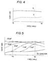
- a test of the antenna reception sensitivity to an FM broadcasting band resulted in a low gain as indicated by a broken curve A in a reception sensitivity graph of Fig. 2.
- a capacitor 27 connected across the power supply lines 17 and 18 between the choke coils 16a and 16b, and the heating conductor 10, as indicated within a block 26 in Fig. 3.
- the capacitor 27 serves to compensate for a change in the effective length of the heating conductor 10 resulting from the connection of the heating power supply lines 17 and 18 thereto.
- the capacitor 27 will compensate for an increase in the leakage of radio signals of higher frequencies such as FM broadcasting band through the choke coils 16a and 16b from the heating conductor 10 due to the capacitance in the choke coils which causes the impedance across each choke coil 16a, 16b to be decreased for higher frequencies. Therefore, with the capacitor 27, the arrangement of Fig. 3 can provide an increased antenna gain for a band of higher frequencies such as FM band covering at least 76 to 90 MHz while maintaining a satisfactory antenna gain for another band of relatively low radio frequencies such as AM broadcasting band covering at least 600 to 1600 KHz.
- a test of reception sensitivity of the antenna arrangement with the capacitor 27 has indicated a greatly improved antenna gain for the entire range of FM broadcasting band as shown in a solid curve B in Fig. 4 as compared with the curve A measured without the capacitor 27.
- Fig. 5 shows test results of reception sensitivity to the FM band using several different capacitive values of the capacitor 27. As noted, the peak of the antenna gain shifts to lower frequencies as the capacitance increases.
- the optimal capacitance of the capacitor 27 depends considerably on the electrical characteristics of the choke coils which is a function of their type, form, size and so an. According to tests, however, the capacitor with a capacitance between approximately 5 pico farads to 0.1 micro farads served to improve the reception sensitivity to FM band of 76 to 90 MHz. In particular, a capacitance between 30 to 200 pico farads yielded most desirable results.
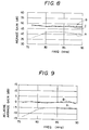
- the addition of the capacitor 27 maintains reception sensitivity to AM broadcasting band of 600 to 1600 KHz as demonstrated in Fig. 6 which shows a relative reception sensitivity with the capacitor 27 as compared with that of no capacitor 27, normalized by zero decibel in Fig. 6.
- the symmetrical antenna elements 23 to 25 is expected to improve the radio signal condition in the heating conductor 10.
- the antenna elements 23 to 25 did improved antenna characteristics for FM broadcasting band.
- each curve A was obtained when the antenna elements 23 to 25 were omitted from the arrangement of Fig. 3.
- each curve B was obtained with the antenna elements 23 to 25, and each curve C was obtained with a pillar or rod antenna of 920 millimeters.
- Fig. 7 shows maximum reception sensitivity while Fig. 8 shows averaged reception sensitivity, and
- Fig. 9 shows a relative reception sensitivity with and without antenna elements 23 to 25 in relation to zero decibel reference of the pillar antenna.
- the addition of the antenna elements 23 to 25 makes a significant improvement of reception sensitivity for FM band over the arrangement without the antenna elements 23 to 25.
- the reception sensitivity with the antenna elements 23 to 25 are noted as good as that obtained from pillar antennas.
- the antenna elements 23 - 25 can serve to improve antenna directivity.
- Fig. 10 shows antenna directivity measured with the arrangement of Fig. 3 with the antenna elements 23 - 25, using horizontally polarized radio waves at 76, 78, 80, 82, 84, 86, 88, 90 MHz, respectively.
- a substantially circular or omnidirectional antenna directivity was obtained i.e., the antenna gain was substantially constant irrespective of the direction of the radio wave in relation to the antenna.
- Fig. 11 shows antenna directivity of the arrangement of Fig. 3 measured with vertically polarized radio waves in FM band.
- the resultant antenna directivity has indicated an ⁇ curve with the minimum antenna gain when the radio wave is applied in forward and backward direction in relation to the antenna.
- This is in contrast to the prior art glass antenna FM antenna which provide antenna directivity of an 8 shape with the minimum antenna gain when the radio wave is applied in a direction horizontally and laterally crossing the antenna. Therefore, a combination of the prior art antenna with the arrangement of Fig. 3 will constitute a most useful diversity antenna system with optimized antenna directivity for vertically polarized radio waves.
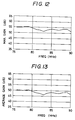
- Fig. 12 shows maximum antenna reception sensitivity
- Fig. 13 shows average antenna reception sensitivity, both measured with the arrangement of Fig. 3 using vertically polarized radio waves in FM band of 75 to 90 MHz.
- the resultant sensitivity is as good as that obtained with horizontally polarized radio waves (see Figs 7 and 8). Therefore, the addition of the antenna elements 23 to 25 serves to improve radio reception sensitivity to FM band of vertically polarized radio signals as well.
- a glass window antenna in which the auxiliary coupling antenna element 25 in Fig. 3 is omitted.
- antenna reception sensitivity to FM band was somewhat concaved as indicated by a curve B in Fig. 15 in which the curve C was measured with the element 25 and the curve A was obtained without any of the antenna elements 23 to 25.
- the addition of the auxiliary antenna element 25 disposed between the antenna elements 23 and 24 has flattened the radio reception sensitivity over the substantially entire range of FM band.
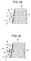
- Figs. 16 to 19 show modifications of the embodiments of Fig. 3 in respect of the location and connection of the capacitor 27.
- the capacitor is connected across taps 28 and 29 provided in the respective choke coils 16a and 16b.
- the capacitor 27 is connected across the heating power supply lines 17 and 18 at a position between the choke coil assembly 26 to the heating conductor 10.
- An appropriate choice of the location of the power supply lines 17 and 18 where the capacitor 27 is connected thereacross may optimize the antenna characteristics.
- auxiliary terminals or connecting pads 32 and 33 may be provided near the ends 30 and 31 of the buses 3 and 4 to connect the capacitor 27 between the pads 32 and 33.
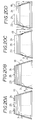
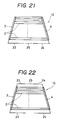
- Fig. 20A - 20D, 21 and 22 show other modifications of the embodiment of Fig. 3 in respect of the antenna elements 23 - 25.
- a plurality of parallel wires 23 - 25 are employed to increase the associated capacitance so that the arrangement of Fig. 20A will be useful for a broad band antenna.
- a plurality of parallel and staggered or offset wires 23 - 25 are employed to improve the frequency characteristic.
- each power supply bus 3, 4 is made short and some heating wires connected to the buses 3 and 4 extend obliquely at part hereof as shown.
- an equivalent length of the buses 3 and 4 is indicated by l.
- the antenna elements 23 - 25 are formed on the bottom margin of the window 1 while in Fig. 22, a first set of antenna elements 23 - 25 is formed on the top margin of the window 1 and a second set of antenna elements 23 and 24 is formed on the bottom margin of the window.
Landscapes
- Details Of Aerials (AREA)
Claims (10)
- Scheibenantenne zur Verwendung in einem Kraftfahrzeug, mit:- einer Heizleitereinrichtung, die auf einer Scheibe ausgebildet ist und eine linke vertikale Spannungsversorgungsbus-Einrichtung (3; 3, 4), eine rechte vertikale Spannungsversorgungsbus-Einrichtung (5) und Heizdrähte (2), die sich horizontal zwischen den Spannungsversorgungsbus-Einrichtungen erstrecken, aufweist; und- einem ersten und einem zweiten Antennenelement (23, 24), die mit der Heizleitereinrichtung verbunden sind;dadurch gekennzeichnet, daß- das erste Antennenelement (23) mit der linken Spannungsversorgungsbus-Einrichtung (3; 4) verbunden ist;- das zweite Antennenelement (24) mit der rechten Spannungsversorgungsbus-Einrichtung (5) verbunden ist;- wobei das erste und zweite Antennenelement im wesentlichen symmetrisch in bezug auf die vertikale Symmetrieachse der Heizleitereinrichtung angeordnet sind und- ein drittes Antennenelement (25) in axialer Ausrichtung zwischen dem ersten und zweiten Antennenelement auf der Glasscheibe angeordnet ist und vom ersten und zweiten Antennenelement so beabstandet ist, daß es elektrisch von diesem getrennt ist.
- Scheibenantenne nach Anspruch 1, ferner mit einer Speiseeinrichtung (22), die an die Heizleitereinrichtung angeschlossen ist, um Signale zu sammeln und zu leiten, die in der Heizleitereinrichtung und den Antennenelementen empfangen werden.
- Scheibenantenne nach Anspruch 2, bei der die Speiseeinrichtung (22) Signale leitet, die sowohl das AM- als auch das FM-Rundfunkband überdecken, wie sie für Radioempfang-Schaltungsanordnungen zur Verfügung stehen.
- Scheibenantenne nach Anspruch 1, ferner mit einer Kopplungseinrichtung (27) zum kapazitiven Koppeln der Antennenelemente (23, 24) miteinander.
- Scheibenantenne nach Anspruch 1, bei der die linke vertikale Spannungsversorgungsbus-Einrichtung einen einzelnen Bus aufweist, der mit einer Spannungsversorgungsleitung (17) verbunden ist, und die rechte vertikale Spannungsversorgungsbus-Einrichtung einen einzelnen Bus (5) aufweist, der mit einer anderen Spannungsversorgungsleitung (18) verbunden ist.
- Scheibenantenne nach Anspruch 1, bei der die linke oder rechte vertikale Spannungsversorgungsbus-Einrichtung einen mit einer Spannungsversorgungsleitung (17) verbundenen unteren Bus (3) und einen mit einer anderen Spannungsversorgungsleitung (18) verbundenen oberen Bus (4) aufweist, und bei der die andere vertikale Spannungsversorgungsbus-Einrichtung einen einzelnen Bus (5) aufweist.
- Scheibenantenne nach Anspruch 1, ferner mit Drosselspulen (16a, 16b) mit einem Paar Spannungsversorgungsleitungen (17, 18), die die Drosselspulen mit der Heizleitereinrichtung verbinden, um dieser Heizleitereinrichtung Heizstrom zuzuführen, und mit einem Kondensator (27), der zwischen die Spannungsversorgungsleitungen geschaltet ist.
- Scheibenantenne nach Anspruch 7, bei der der Kondensator (27) eine Kapazität aufweist, die zwischen 5 Pikofarad und 0,1 Mikrofarad liegt.
- Scheibenantenne nach Anspruch 8, bei der der Kondensator (27) eine Kapazität aufweist, die zwischen 30 und 200 Pikofarad liegt.
- Scheibenantenne nach Anspruch 1, ferner mit Antennenelementen, die sich zwischen der linken vertikalen Spannungsversorgungsbus-Einrichtung (3) und der rechten vertikalen Spannungsversorgungsbus-Einrichtung (5) erstrecken.
Applications Claiming Priority (4)
| Application Number | Priority Date | Filing Date | Title |
|---|---|---|---|
| JP142518/88U | 1988-10-31 | ||
| JP14251888U JPH0262813U (de) | 1988-10-31 | 1988-10-31 | |
| JP15564288U JPH0619205Y2 (ja) | 1988-11-30 | 1988-11-30 | 窓ガラスアンテナ |
| JP155642/88U | 1988-11-30 |
Publications (3)
| Publication Number | Publication Date |
|---|---|
| EP0367225A2 EP0367225A2 (de) | 1990-05-09 |
| EP0367225A3 EP0367225A3 (en) | 1990-08-08 |
| EP0367225B1 true EP0367225B1 (de) | 1994-12-28 |
Family
ID=26474497
Family Applications (1)
| Application Number | Title | Priority Date | Filing Date |
|---|---|---|---|
| EP89120192A Expired - Lifetime EP0367225B1 (de) | 1988-10-31 | 1989-10-31 | Scheibenantenne für Kraftfahrzeuge |
Country Status (3)
| Country | Link |
|---|---|
| US (1) | US5113195A (de) |
| EP (1) | EP0367225B1 (de) |
| DE (1) | DE68920277T2 (de) |
Families Citing this family (14)
| Publication number | Priority date | Publication date | Assignee | Title |
|---|---|---|---|---|
| GB2266189B (en) * | 1992-04-08 | 1996-09-11 | Antiference Ltd | Vehicle antenna |
| KR0145052B1 (ko) * | 1993-12-29 | 1998-08-01 | 와다 요시히로 | 차량용 안테나 및 그 설정방법 |
| DE4401819A1 (de) * | 1994-01-22 | 1995-07-27 | Kolbe & Co Hans | Kabelanordnung |
| DE29606416U1 (de) * | 1996-04-06 | 1996-06-27 | Mekra Rangau Plastics GmbH & Co KG, 90765 Fürth | Außenrückspiegel für Kraftfahrzeuge, insbesondere Nutzfahrzeuge |
| US5781160A (en) * | 1996-05-31 | 1998-07-14 | The Ohio State University | Independently fed AM/FM heated window antenna |
| USD428286S (en) * | 1998-05-29 | 2000-07-18 | Kimberly-Clark Worldwide | Dispenser adapter for coreless rolls of products |
| JP2000114839A (ja) * | 1998-10-05 | 2000-04-21 | Harada Ind Co Ltd | 車両用窓ガラスアンテナ装置 |
| DE10359223A1 (de) * | 2003-12-17 | 2005-07-21 | Robert Bosch Gmbh | Fahrzeugscheibenantenne |
| KR100718375B1 (ko) * | 2005-09-01 | 2007-05-14 | 주식회사 팬택앤큐리텔 | 정전기 방전 차단 기능을 구비한 이동통신 단말기 |
| CN101060193A (zh) * | 2006-04-19 | 2007-10-24 | 旭硝子株式会社 | 汽车用高频玻璃天线及汽车用后窗玻璃板 |
| CN103518324B (zh) * | 2011-05-09 | 2016-06-15 | 株式会社村田制作所 | 阻抗变换电路以及通信终端装置 |
| CN105453336A (zh) * | 2013-08-05 | 2016-03-30 | 旭硝子株式会社 | 天线装置 |
| FR3076169A1 (fr) * | 2017-12-21 | 2019-06-28 | Psa Automobiles Sa | Dispositif de chauffage a filtre a impedances de mode commun couplees pour une vitre a antenne de reception d’ondes radiophoniques |
| FR3076168B1 (fr) * | 2017-12-21 | 2021-09-24 | Psa Automobiles Sa | Dispositif de chauffage a filtre differentiel pour une vitre a antenne de reception d’ondes radiophoniques |
Family Cites Families (14)
| Publication number | Priority date | Publication date | Assignee | Title |
|---|---|---|---|---|
| FR2250329A5 (de) * | 1973-10-31 | 1975-05-30 | Saint Gobain | |
| US4063247A (en) * | 1976-10-07 | 1977-12-13 | Nippon Sheet Glass Co., Ltd. | Heater glass sheet with broad band receiver antennae |
| GB1600987A (en) * | 1977-08-17 | 1981-10-21 | Bsh Electronics Manchester Ltd | Electrical device to enable the heating element of an electrically heated motor vehicle window to be used as a radio transmitting aerial |
| JPS57188102A (en) * | 1981-05-15 | 1982-11-19 | Asahi Glass Co Ltd | Glass antenna for automobile |
| DE3409876A1 (de) * | 1984-03-17 | 1985-09-19 | Robert Bosch Gmbh, 7000 Stuttgart | Heizscheibenantenne |
| JPS61203702A (ja) * | 1985-03-07 | 1986-09-09 | Asahi Glass Co Ltd | 自動車用アンテナ装置 |
| JPS6130102A (ja) * | 1984-07-20 | 1986-02-12 | Nippon Sheet Glass Co Ltd | 自動車用窓ガラスのアンテナ |
| JPS6173403A (ja) * | 1984-09-19 | 1986-04-15 | Nissan Motor Co Ltd | 自動車用ガラスアンテナ |
| JPS61175010A (ja) * | 1985-01-31 | 1986-08-06 | Hino Motors Ltd | 成形方法 |
| JPH0640769B2 (ja) * | 1986-02-18 | 1994-06-01 | 株式会社スズテック | 育苗箱用条播装置 |
| JPS6326925A (ja) * | 1986-07-18 | 1988-02-04 | Matsushita Electronics Corp | マグネトロン |
| JPS63131704A (ja) * | 1986-11-21 | 1988-06-03 | Harada Kogyo Kk | ガラスアンテナの補償増幅装置 |
| GB2200498B (en) * | 1986-12-19 | 1990-07-18 | Central Glass Co Ltd | Vehicle window glass antenna using transparent conductive film |
| KR890001219A (ko) * | 1987-06-27 | 1989-03-18 | 노브오 사수가 | 자동차용 수신장치 |
-
1989
- 1989-10-26 US US07/427,587 patent/US5113195A/en not_active Expired - Fee Related
- 1989-10-31 DE DE68920277T patent/DE68920277T2/de not_active Expired - Fee Related
- 1989-10-31 EP EP89120192A patent/EP0367225B1/de not_active Expired - Lifetime
Also Published As
| Publication number | Publication date |
|---|---|
| EP0367225A3 (en) | 1990-08-08 |
| US5113195A (en) | 1992-05-12 |
| DE68920277T2 (de) | 1995-08-03 |
| EP0367225A2 (de) | 1990-05-09 |
| DE68920277D1 (de) | 1995-02-09 |
Similar Documents
| Publication | Publication Date | Title |
|---|---|---|
| KR0148588B1 (ko) | 자동차용 다이버시티 유리 안테나 | |
| US5905468A (en) | Glass antenna device for vehicles | |
| EP0418047B1 (de) | Scheibenantenne für Kraftfahrzeuge | |
| US6229493B1 (en) | Glass antenna device for vehicle | |
| EP0367225B1 (de) | Scheibenantenne für Kraftfahrzeuge | |
| US5610619A (en) | Backlite antenna for AM/FM automobile radio having broadband FM reception | |
| JP2009049706A (ja) | 車両用ガラスアンテナ | |
| JPS61100004A (ja) | アンテナ素子付自動車用窓ガラス | |
| US6064345A (en) | Glass antenna device for an automobile | |
| EP0942486B1 (de) | Scheibenantennenanordnung für Fahrzeug | |
| US5239302A (en) | Wave reception apparatus for a motor vehicle | |
| US5790079A (en) | Backlite antenna for AM/FM automobile radio | |
| JPH0113643B2 (de) | ||
| JPH11205023A (ja) | 車両用ガラスアンテナ装置 | |
| GB2309829A (en) | Vehicle on-screen antenna | |
| JPH0756495Y2 (ja) | 自動車窓用アンテナ装置 | |
| EP0370714B2 (de) | Apparat zum Wellenempfang für einen PKW | |
| JPH0969712A (ja) | 自動車用ガラスアンテナ | |
| JPS63292702A (ja) | 除曇ヒ−タ線付き自動車用窓ガラス | |
| GB2316538A (en) | Vehicle windscreen antenna and heater element arrangement | |
| JP3500697B2 (ja) | 自動車tv帯受信用リアガラスアンテナ | |
| JP3648910B2 (ja) | 車両用アンテナ | |
| JP2737165B2 (ja) | 自動車用ガラスアンテナ装置 | |
| JPH0136335Y2 (de) | ||
| JPH09181513A (ja) | 自動車用ガラスアンテナ装置 |
Legal Events
| Date | Code | Title | Description |
|---|---|---|---|
| PUAI | Public reference made under article 153(3) epc to a published international application that has entered the european phase |
Free format text: ORIGINAL CODE: 0009012 |
|
| AK | Designated contracting states |
Kind code of ref document: A2 Designated state(s): DE FR |
|
| PUAL | Search report despatched |
Free format text: ORIGINAL CODE: 0009013 |
|
| AK | Designated contracting states |
Kind code of ref document: A3 Designated state(s): DE FR |
|
| 17P | Request for examination filed |
Effective date: 19900803 |
|
| 17Q | First examination report despatched |
Effective date: 19920910 |
|
| GRAA | (expected) grant |
Free format text: ORIGINAL CODE: 0009210 |
|
| AK | Designated contracting states |
Kind code of ref document: B1 Designated state(s): DE FR |
|
| REF | Corresponds to: |
Ref document number: 68920277 Country of ref document: DE Date of ref document: 19950209 |
|
| ET | Fr: translation filed | ||
| PLBE | No opposition filed within time limit |
Free format text: ORIGINAL CODE: 0009261 |
|
| STAA | Information on the status of an ep patent application or granted ep patent |
Free format text: STATUS: NO OPPOSITION FILED WITHIN TIME LIMIT |
|
| 26N | No opposition filed | ||
| PGFP | Annual fee paid to national office [announced via postgrant information from national office to epo] |
Ref country code: FR Payment date: 20021008 Year of fee payment: 14 |
|
| PGFP | Annual fee paid to national office [announced via postgrant information from national office to epo] |
Ref country code: DE Payment date: 20021031 Year of fee payment: 14 |
|
| PG25 | Lapsed in a contracting state [announced via postgrant information from national office to epo] |
Ref country code: DE Free format text: LAPSE BECAUSE OF NON-PAYMENT OF DUE FEES Effective date: 20040501 |
|
| PG25 | Lapsed in a contracting state [announced via postgrant information from national office to epo] |
Ref country code: FR Free format text: LAPSE BECAUSE OF NON-PAYMENT OF DUE FEES Effective date: 20040630 |
|
| REG | Reference to a national code |
Ref country code: FR Ref legal event code: ST |