EP0367602B1 - Magnetkerne - Google Patents
Magnetkerne Download PDFInfo
- Publication number
- EP0367602B1 EP0367602B1 EP89311350A EP89311350A EP0367602B1 EP 0367602 B1 EP0367602 B1 EP 0367602B1 EP 89311350 A EP89311350 A EP 89311350A EP 89311350 A EP89311350 A EP 89311350A EP 0367602 B1 EP0367602 B1 EP 0367602B1
- Authority
- EP
- European Patent Office
- Prior art keywords
- tape
- thin metal
- wound
- magnetic core
- tapes
- Prior art date
- Legal status (The legal status is an assumption and is not a legal conclusion. Google has not performed a legal analysis and makes no representation as to the accuracy of the status listed.)
- Expired - Lifetime
Links
Images

Classifications
-
- H—ELECTRICITY
- H01—ELECTRIC ELEMENTS
- H01F—MAGNETS; INDUCTANCES; TRANSFORMERS; SELECTION OF MATERIALS FOR THEIR MAGNETIC PROPERTIES
- H01F1/00—Magnets or magnetic bodies characterised by the magnetic materials therefor; Selection of materials for their magnetic properties
-
- H—ELECTRICITY
- H01—ELECTRIC ELEMENTS
- H01F—MAGNETS; INDUCTANCES; TRANSFORMERS; SELECTION OF MATERIALS FOR THEIR MAGNETIC PROPERTIES
- H01F3/00—Cores, Yokes, or armatures
- H01F3/04—Cores, Yokes, or armatures made from strips or ribbons
-
- H—ELECTRICITY
- H01—ELECTRIC ELEMENTS
- H01F—MAGNETS; INDUCTANCES; TRANSFORMERS; SELECTION OF MATERIALS FOR THEIR MAGNETIC PROPERTIES
- H01F41/00—Apparatus or processes specially adapted for manufacturing or assembling magnets, inductances or transformers; Apparatus or processes specially adapted for manufacturing materials characterised by their magnetic properties
- H01F41/02—Apparatus or processes specially adapted for manufacturing or assembling magnets, inductances or transformers; Apparatus or processes specially adapted for manufacturing materials characterised by their magnetic properties for manufacturing cores, coils, or magnets
- H01F41/0206—Manufacturing of magnetic cores by mechanical means
- H01F41/0213—Manufacturing of magnetic circuits made from strip(s) or ribbon(s)
- H01F41/0226—Manufacturing of magnetic circuits made from strip(s) or ribbon(s) from amorphous ribbons
-
- Y—GENERAL TAGGING OF NEW TECHNOLOGICAL DEVELOPMENTS; GENERAL TAGGING OF CROSS-SECTIONAL TECHNOLOGIES SPANNING OVER SEVERAL SECTIONS OF THE IPC; TECHNICAL SUBJECTS COVERED BY FORMER USPC CROSS-REFERENCE ART COLLECTIONS [XRACs] AND DIGESTS
- Y10—TECHNICAL SUBJECTS COVERED BY FORMER USPC
- Y10T—TECHNICAL SUBJECTS COVERED BY FORMER US CLASSIFICATION
- Y10T29/00—Metal working
- Y10T29/49—Method of mechanical manufacture
- Y10T29/49002—Electrical device making
- Y10T29/4902—Electromagnet, transformer or inductor
- Y10T29/49071—Electromagnet, transformer or inductor by winding or coiling
-
- Y—GENERAL TAGGING OF NEW TECHNOLOGICAL DEVELOPMENTS; GENERAL TAGGING OF CROSS-SECTIONAL TECHNOLOGIES SPANNING OVER SEVERAL SECTIONS OF THE IPC; TECHNICAL SUBJECTS COVERED BY FORMER USPC CROSS-REFERENCE ART COLLECTIONS [XRACs] AND DIGESTS
- Y10—TECHNICAL SUBJECTS COVERED BY FORMER USPC
- Y10T—TECHNICAL SUBJECTS COVERED BY FORMER US CLASSIFICATION
- Y10T29/00—Metal working
- Y10T29/49—Method of mechanical manufacture
- Y10T29/49002—Electrical device making
- Y10T29/4902—Electromagnet, transformer or inductor
- Y10T29/49075—Electromagnet, transformer or inductor including permanent magnet or core
- Y10T29/49078—Laminated
-
- Y—GENERAL TAGGING OF NEW TECHNOLOGICAL DEVELOPMENTS; GENERAL TAGGING OF CROSS-SECTIONAL TECHNOLOGIES SPANNING OVER SEVERAL SECTIONS OF THE IPC; TECHNICAL SUBJECTS COVERED BY FORMER USPC CROSS-REFERENCE ART COLLECTIONS [XRACs] AND DIGESTS
- Y10—TECHNICAL SUBJECTS COVERED BY FORMER USPC
- Y10T—TECHNICAL SUBJECTS COVERED BY FORMER US CLASSIFICATION
- Y10T29/00—Metal working
- Y10T29/49—Method of mechanical manufacture
- Y10T29/49789—Obtaining plural product pieces from unitary workpiece
-
- Y—GENERAL TAGGING OF NEW TECHNOLOGICAL DEVELOPMENTS; GENERAL TAGGING OF CROSS-SECTIONAL TECHNOLOGIES SPANNING OVER SEVERAL SECTIONS OF THE IPC; TECHNICAL SUBJECTS COVERED BY FORMER USPC CROSS-REFERENCE ART COLLECTIONS [XRACs] AND DIGESTS
- Y10—TECHNICAL SUBJECTS COVERED BY FORMER USPC
- Y10T—TECHNICAL SUBJECTS COVERED BY FORMER US CLASSIFICATION
- Y10T29/00—Metal working
- Y10T29/49—Method of mechanical manufacture
- Y10T29/49789—Obtaining plural product pieces from unitary workpiece
- Y10T29/49794—Dividing on common outline
Definitions
- This invention relates to laminated magnetic cores produced by winding up thin metal tape, and methods of making them.
- amorphous thin metal magnetic tapes have attracted attention as materials for constructing the magnetic cores of transformers and magnetic cores of magnetic amplifiers, on account of their very superior magnetic properties.
- Such magnetic cores fabricated from amorphous thin metal tapes are produced by winding up thin metal tape into the required shape.
- such magnetic cores may be toroidal cores or cut cores.
- cut cores employing amorphous thin metal tapes are manufactured as follows.
- the amorphous thin metal tape is first laminated by winding up to the desired shape on a winding jig. It is then subjected to heat treatment ment below the crystallization temperature, in order to remove strain in the amorphous thin metal tape and to obtain good magnetic properties. It is then cut at the appropriate places to produce a cut core shape.
- magnetic cores employing a wound-up body consisting of amorphous thin metal tape are subject to the problem of increased core loss, caused by forces of contraction, etc., that are produced during hardening of the impregnating resin. Furthermore, there is the problem that low core loss, in particular when wide amorphous thin metal tape is used, cannot be obtained simply by decreasing the force of contraction of the resin.
- the shape of the amorphous thin metal tape itself In connection with the problems discussed above, we have made a series of investigations regarding the shape of the amorphous thin metal tape itself. As a result, it has now been discovered that one cause of increased core loss is attributable to deformation of shape, e.g., the cross-sectional shape in the direction of lamination of the wound body becomes trapezoidal. This occurs because there is considerable fluctuation of sheet thickness in the width direction of amorphous thin metal tape manufactured by the super-quenching method employing a single roll, which is the normally used method of manufacturing amorphous thin metal tapes.
- the thin film In the conventional super-quenching single roll manufacturing method, the thin film has a rolled side or face formed adjacent the quenching roll and a free face on the other side thereof. In this method, liquid amorphous metal is spread over a cold quenching roll to solidify the liquid thus forming the film.
- An object of the invention is to provide magnetic cores having low core loss, and methods of making them, by compensating for fluctuation in sheet thickness in the width direction of thin metal tape formed by the single roll method.
- the invention is directed to a magnetic core having a wound-up laminated body of at least two thin metal tapes said metal tapes wound together in contacting relationship along the length thereof, each of said metal tapes having a thickness which varies across its width, the thickness of contacting adjacent tapes varying oppositely across their widths so that the thickness of the wound-up laminated body at the two ends in the width direction is substantially equal.
- the invention is also directed to a method of making a magnetic core comprising the steps of: forming a thin metal tape having a rolled face and a free face; cutting said thin metal tape lengthwise to form at least two tapes of equal width; superimposing said at least two tapes on one another to form an at least two layer tape of substantially rectangular cross-section; and winding and laminating said at least two-layer tape into a given shape.
- the thin metal tape used in the invention is formed by the super-quenching method using a single roll. It is preferred that the difference in sheet thickness of the two ends in the width direction of the thin metal tape is, on average, at least approximately 2 ⁇ m. It is further preferred if the width of the thin metal tape is at least 10 mm, has a thickness of 10 ⁇ m to 50 ⁇ m, and if the number of wound-up layers is at least 50.
- Fe-based amorphous alloy of large magnetostriction represented by the general formula: Fe a M b Y c
- M is at least one element selected from the group Ti, V, Cr, Mn, Co, Hi, Zr, Hb, Mo, Hf, Ta, W, Re, Ga, Ru, Rh, Pd, Os, Ir, Pt, and rare earth elements
- Y is at least one element selected from the group of Si, B, P, and C
- a, b, and c indicate numbers satisfying the relationships 65 ⁇ a ⁇ 85, 0 ⁇ b ⁇ 15, 5 ⁇ c ⁇ 35
- Co-based amorphous alloy whereof the absolute value of the magnetostriction constant is not more than 2 X 10 ⁇ 6, represented by the general formula: Co x M' y Y z where, in this formula, M' is at least one element selected from the group consisting of
- soft magnetic thin metal tape consisting of a soft magnetic alloy having fine crystal grains of about 5 nm to 30 nm, expressed by the general formula: where, in this formula, X is at least one element selected from the group Ni and Co, and M'' is at least one element selected from the group Nb and Mo, and m, n, p, q, and r are numbers satisfying respectively 0 ⁇ m ⁇ 0.3, 0.1 ⁇ n ⁇ 5, 0.1 ⁇ p ⁇ 5, 5 ⁇ q ⁇ 25, 3 ⁇ r ⁇ 15, 15 ⁇ q + r ⁇ 30.
- the magnetic core of the invention is manufactured for example as follows.
- Thin metal tape consisting of a material as described above is initially manufactured using the single roll method.
- a wound-up body is manufactured by taking at least two thin metal tapes obtained from the same forming lot, superimposing their rolled faces on one another or their free faces on one another, and winding them up on a winding jig, in this condition, to form a magnetic core of the required shape. It should be noted that it is not necessarily essential that the entire wound-up body should be of the above-described two-layer winding, so long as the major portion is wound by this method.
- a toroidal core is obtained by performing heat treatment for strain removal and improvement of magnetic properties of the wound-up body. Also, in the case of a cut core, after carrying out heat treatment for strain removal and improvement of magnetic properties on the wound-up body that is obtained, it is impregnated with epoxy resin or inorganic polymer and a hardening treatment is carried out to effect fixing between the layers of the wound-up body. If an inorganic polymer is used, heat treatment and hardening treatment can be performed simultaneously in order to improve the properties. After this, a cut core is obtained by cutting to the required final shape.
- the difference in sheet thickness of the two ends in the width direction of thin metal tape obtained using the single roll method is about 5 ⁇ m. It is therefore possible to compensate for this difference in sheet thickness, so far as the overall wound-up body is concerned, by carrying out winding-up lamination in such a way that thin metal tapes from the same forming lot are superimposed, with corresponding rolled faces, or corresponding free faces, facing each other.
- a wound-up body is obtained in which the stress is applied practically uniformly, and the increased core loss caused by non-uniformity of stress or very large locally applied stress can be prevented.
- resin is impregnated between the layers of the wound-up body, satisfactory permeation of the resin between the layers can be achieved. This also helps to prevent increase in core loss.
- Amorphous alloy thin tape of width 50 mm and having an alloy composition expressed by: (Fe 0.97 , Cr 0.03 )79 Si10 B11 was manufactured by the single roll method. Although fluctuation was seen in the sheet thickness at the two end regions in the width direction of the amorphous alloy thin tape obtained, the mean values obtained were practically 18 ⁇ m and 23 ⁇ m at the respective ends.
- a wound-up body was manufactured by cutting this amorphous alloy thin tape into two in the length direction to form two equal width strips, each half the original width, and placing the rolled faces against each other (or the free faces against each other), and then winding up these two tape layers to the required shape on a winding jig to a winding layer thickness of 20 mm.
- this wound-up body was subjected to heat treatment at a temperature of 420°C, for 80 minutes. It was then impregnated with epoxy resin, and hardening treatment carried out, thereby fixing the wound-up body.
- Fig. 1 is a view showing the cross-section in the direction of lamination of the cut core thus obtained.
- the wound-up body 1 that is obtained the rolled faces 2a and free faces 2b of the amorphous alloy thin tape 2 are arranged adjacent each other.
- the result is that the thickness of the wound-up layers at the two ends in the width direction of the thin tape is practically equal. Consequently, the stress distribution of the wound-up body as a whole is also practically uniform.
- the arrangement of the two-layer film before rolling is such as to obtain a substantially rectangular cross-section for the superimposed two layers. It is possible to obtain a substantially rectangular cross-section in some cases where the free face of the first film is superimposed on the rolled face of the second film to form the two-layer film which is subsequently rolled. In other cases, it is possible to utilize more than two films which are oriented such that the cross-sectional area of the film composition (before rolling) is of a substantially rectangular cross-sectional area.
- a rectangular cut core for transformer use was obtained by manufacturing a wound-up body of the same shape by single-layer winding, using the same amorphous alloy thin tape manufactured in Embodiment I.
- Fig. 2 is a view showing the cross-section in the direction of lamination of the cut core of Comparative Example 1 that was thus obtained.
- rolled faces 2a and free faces 2b of the amorphous alloy thin tape 2 are arranged adjacently facing each other.
- the wound-up layer thickness at the two end regions in the width direction of the thin tape is considerably different. The result is that stress is concentrated on the side of smaller sheet thickness in the width direction of the thin tape.
- the core loss was determined under the same conditions as in Embodiment 1 for the rectangular cut core for transformer use of this comparative Example 1. The results are also shown in Table 1.
- the core loss of the magnetic core of this embodiment is reduced by about 30%. Also, since, for the magnetic core of Embodiment 1, two layers of tape were wound up simultaneously, the winding-up time for forming the wound-up body can be reduced.
- Amorphous alloy thin tape of the alloy composition: Fe 73.5 Cu 1.5 Nb 3.0 Si 15.5 B 6.5 was manufactured by the single roll method as a sample of width 25 mm.
- the sheet thicknesses at the two ends in the width direction of the amorphous alloy thin tape obtained were respectively about 21 ⁇ m and 25 ⁇ m on average, though there was some fluctuation.
- a wound-up body was manufactured by cutting this amorphous alloy thin tape into two in the length direction, placing rolled faces (or free faces) on top of each other, and winding up the resulting two tape layers together on a winding jig to the required shape to give a wound-up layer thickness of 20 mm.
- this wound-up body was subjected to heat treatment at a temperature of 550°C higher than the crystallization temperature of this alloy thin tape, for 60 minutes in a nitrogen atmosphere. It was then impregnated with epoxy resin and hardening treatment performed, to obtain a fixed wound-up body.
- the core loss of this cut core was determined under the measurement conditions shown in Table 2.
- Amorphous alloy thin tape of the alloy composition represented by: [(Co 0.95 Fe 0.05 ) 0.96 Cr 0.04 ]74Si14B12 was manufactured by the single roll method as a sample of width 20 mm.
- the sheet thickness at the two ends in the width direction of the amorphous alloy thin tape that was obtained were on average 18 ⁇ m and 22 ⁇ m respectively, though fluctuations were observed.
- this amorphous alloy thin tape was divided into two in the longitudinal direction, and rolled faces (or free faces) were placed on top of each other, and a wound-up body of external diameter 600 mm X internal diameter 400 mm X height 40 mm was manufactured by winding up these two tape layers simultaneously on a winding jig, to the required shape.
- a toroidal core was manufactured by performing heat treatment on this wound-up body under the conditions 430°C, 40 minutes.
- a toroidal core was manufactured by producing a wound-up body of the same shape, but by winding up a single tape layer, using the amorphous alloy thin tape described above, and carrying out heat treatment under the same conditions.
- the core loss of the toroidal core of this embodiment was reduced by about 15%.
- the dimensional accuracy of the toroidal core of Embodiment 3 was excellent.
- the tape was closely wound on one side in the width direction of the amorphous alloy thin tape, on the other side, it appeared rather loose.
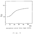
- Amorphous alloy thin tape having the alloy composition represented by Fe78Si9B13 was manufactured as a sample of width 50 mm by the single roll method.
- this amorphous alloy thin tape was cut in the longitudinal direction so as to provide a number of different widths, to produce amorphous alloy thin tapes of various different widths.
- these amorphous alloy thin tapes were divided into two in the longitudinal direction and rolled faces (or free faces) were placed on top of each other. Respective wound-up bodies were produced by winding up these two tape layers simultaneously to the required shape on a winding jig, the ratio between width and thickness of the wound-up layers in each case being 1 : 1.
- toroidal cores were manufactured by heat treatment of these wound-up bodies under the conditions 400°C, 2 hours, followed by resin moulding.
- toroidal cores were manufactured in the same way as above, using the amorphous alloy thin tapes of the various different widths used in the above embodiment, except that the wound-up bodies were formed by winding up these amorphous alloy thin tapes from a single tape layer only.
- the results are shown in Fig. 3, in the form of the relationship between the width of the amorphous alloy thin tape and the ratio (P0/P) of the core loss P0 of the toroidal cores of the comparative example and the core loss P of the toroidal cores of the embodiment, using amorphous alloy thin tape of the same width.
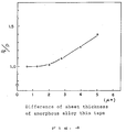
- Amorphous alloy thin tape of a plurality of different types was manufactured, in which the difference in sheet thickness in the width direction was varied by altering the tape manufacturing conditions, using the single roll method and employing alloy having the composition represented by: (Co 0.91 Fe 0.93 Mn 0.04 Nb 0.02 )74Si14B12.
- the width of the thin tape was 25 mm.
- these amorphous alloy thin tapes were divided into two in the lengthwise direction and rolled faces (or free faces) were superimposed, and wound-up bodies of external diameter 60 mm X internal diameter 40 mm were produced by simultaneously winding up these two tape layers on a winding jig to the required shape.
- toroidal cores were manufactured by performing heat treatment under the conditions 440°C, 40 minutes on these wound-up bodies.
- respective toroidal cores were manufactured in the same way, except that the wound-up body was formed by winding only one tape layer of amorphous alloy thin tape.
- the results are shown in Fig. 4, in terms of the relationship between the difference of sheet thickness of the amorphous alloy thin tape and the ratio (P0/P) between the core loss P0 of the toroidal cores of the comparative examples and the core loss P of the toroidal cores of the embodiments, when amorphous alloy thin tape of the same sheet thickness difference was used.
- the benefit in terms of core loss reduction is particularly marked when amorphous alloy thin tapes whose difference in sheet thickness in the width direction is at least 2 ⁇ m are used. Also, it can be seen that the benefit is increased as the difference in sheet thickness in the width direction of the amorphous alloy thin tape increases.
- a wound-up body of excellent dimensional accuracy on both sides in the width direction of the metal thin tape is obtained. Consequently, the stress distribution over the whole wound up body is uniform, and a magnetic core having small core loss and excellent magnetic properties can be obtained.
Landscapes
- Engineering & Computer Science (AREA)
- Power Engineering (AREA)
- Manufacturing & Machinery (AREA)
- Manufacturing Cores, Coils, And Magnets (AREA)
- Soft Magnetic Materials (AREA)
Claims (13)
- Magnetkern mit einem aufgewickelten, geschichteten Körper aus wenigstens zwei dünnen Metallbändern, wobei die Metallbänder entlang ihrer Länge so zusammengewickelt sind, daß sie sich berühren, wobei jedes der Metallbänder eine Dicke hat, die sich über seine Breite ändert, wobei sich die Dicke sich berührender, benachbarter Bänder über ihre Breite entgegengesetzt ändert, so daß die Dicke des aufgewickelten, geschichteten Körpers an den beiden Enden in Richtung der Breite im wesentlichen gleich ist.
- Magnetkern nach Anspruch 1, wobei jedes der Metallbänder eine freie, nicht gerollte Fläche auf einer Seite und eine gerollte Fläche auf der anderen Seite hat, wobei entweder (1) gerollte Flächen des dünnen Metallbandes so angeordnet sind, daß sie sich in wenigstens einem Teil des aufgewickelten, geschichteten Körpers einander benachbart gegenüberliegen, oder (2) freie Flächen des dünnen Metallbandes so angeordnet sind, daß sie sich in wenigstens einem Teil des aufgewickelten, geschichteten Körpers gegenüberliegen.
- Magnetkern nach Anspruch 1 oder 2, wobei das dünne Metall eine auf Fe basierende amorphe Legierung aufweist.
- Magnetkern nach einem der vorhergehenden Ansprüche, wobei das dünne Metall eine auf Co basierende amorphe Legierung aufweist.
- Magnetkern nach einem der vorhergehenden Ansprüche, wobei das dünne Metall eine weiche magnetische Legierung mit feinen Kristallkörnern von etwa 5 nm bis 30 nm aufweist.
- Magnetkern nach einem der vorhergehenden Ansprüche, wobei das dünne Metallband eine Dickendifferenz zwischen seinen beiden Enden, in der Richtung seiner Breite, von wenigstens 2 µm hat.
- Magnetkern nach einem der vorhergehenden Ansprüche, wobei das dünne Metallband eine Breite von wenigstens 10 mm hat.
- Magnetkern nach einem der vorhergehenden Ansprüche, wobei das dünne Metallband eine Dicke im Bereich von 10 µm bis 50 µm hat.
- Magnetkern nach einem der vorhergehenden Ansprüche, wobei die Anzahl der aufgewickelten Lagen des aufgewickelten, geschichteten Körpers wenigstens 50 beträgt.
- Verfahren zum Herstellen eines Magnetkerns mit den Schritten:
Formen eines dünnen Metallbandes mit einer gerollten Fläche und einer freien Fläche;
längsweises Schneiden des dünnen Metallbandes, um wenigstens zwei Bänder gleicher Breite zu formen;
Übereinanderlegen der wenigstens zwei Bänder, um ein aus wenigstens zwei Lagen bestehendes Band von im wesentlichen rechteckigem Querschnitt zu formen; und
Wickeln und Schichten des aus wenigstens zwei Lagen bestehenden Bandes in eine gegebene Gestalt. - Verfahren nach Anspruch 10, das den Schritt einschließt, freie Flächen oder gerollte Flächen der wenigstens zwei Bänder übereinanderzulegen, um das aus wenigstens zwei Lagen bestehende Band zu formen.
- Verfahren nach Anspruch 10 oder 11, wobei in dem Schritt zum Formen das dünne Metallband mit einer über seine Breite unterschiedlichen Banddicke geformt wird; und in dem Schritt zum Übereinanderlegen ein relativ dünner Teil des dünnen Metallbandes über einen relativ dicken Teil davon gelegt wird.
- Verfahren nach einem der Ansprüche 10 bis 12, wobei in dem Schritt zum Formen das dünne Metallband aus magnetischem Material geformt wird; und in dem Schritt zum Wickeln und Schichten die gegebene Gestalt den Magnetkern formt.
Applications Claiming Priority (2)
| Application Number | Priority Date | Filing Date | Title |
|---|---|---|---|
| JP63278388A JPH02123710A (ja) | 1988-11-02 | 1988-11-02 | 磁心およびその製造方法 |
| JP278388/88 | 1988-11-02 |
Publications (2)
| Publication Number | Publication Date |
|---|---|
| EP0367602A1 EP0367602A1 (de) | 1990-05-09 |
| EP0367602B1 true EP0367602B1 (de) | 1994-02-02 |
Family
ID=17596649
Family Applications (1)
| Application Number | Title | Priority Date | Filing Date |
|---|---|---|---|
| EP89311350A Expired - Lifetime EP0367602B1 (de) | 1988-11-02 | 1989-11-02 | Magnetkerne |
Country Status (5)
| Country | Link |
|---|---|
| US (2) | US4983943A (de) |
| EP (1) | EP0367602B1 (de) |
| JP (1) | JPH02123710A (de) |
| KR (1) | KR930010640B1 (de) |
| DE (1) | DE68912880T2 (de) |
Families Citing this family (11)
| Publication number | Priority date | Publication date | Assignee | Title |
|---|---|---|---|---|
| US5935347A (en) * | 1993-12-28 | 1999-08-10 | Alps Electric Co., Ltd. | FE-base soft magnetic alloy and laminated magnetic core by using the same |
| US5371650A (en) * | 1994-02-15 | 1994-12-06 | Electronic Concepts, Inc. | Hermetically sealed capacitor and method for making the same |
| US8432167B2 (en) * | 2004-02-09 | 2013-04-30 | Baker Hughes Incorporated | Method and apparatus of using magnetic material with residual magnetization in transient electromagnetic measurement |
| US7859260B2 (en) * | 2005-01-18 | 2010-12-28 | Baker Hughes Incorporated | Nuclear magnetic resonance tool using switchable source of static magnetic field |
| US8294468B2 (en) * | 2005-01-18 | 2012-10-23 | Baker Hughes Incorporated | Method and apparatus for well-bore proximity measurement while drilling |
| DE102005015006B4 (de) * | 2005-04-01 | 2013-12-05 | Vacuumschmelze Gmbh & Co. Kg | Magnetkern |
| WO2008034022A2 (en) * | 2006-09-14 | 2008-03-20 | The Knox Company | Electronic lock and key assembly |
| US9121967B2 (en) | 2007-08-31 | 2015-09-01 | Baker Hughes Incorporated | Method and apparatus for well-bore proximity measurement while drilling |
| WO2012064871A2 (en) | 2010-11-09 | 2012-05-18 | California Institute Of Technology | Ferromagnetic cores of amorphouse ferromagnetic metal alloys and electonic devices having the same |
| US9151150B2 (en) | 2012-10-23 | 2015-10-06 | Baker Hughes Incorporated | Apparatus and methods for well-bore proximity measurement while drilling |
| CN115602405A (zh) * | 2022-10-17 | 2023-01-13 | 宁波中益赛威材料科技有限公司(Cn) | 一种复合磁芯及其制备方法、装置 |
Citations (1)
| Publication number | Priority date | Publication date | Assignee | Title |
|---|---|---|---|---|
| US4847987A (en) * | 1988-08-29 | 1989-07-18 | General Electric Company | Method of making a core and coil assembly |
Family Cites Families (12)
| Publication number | Priority date | Publication date | Assignee | Title |
|---|---|---|---|---|
| US3465273A (en) * | 1967-12-14 | 1969-09-02 | Hunterdon Transformer Co | Toroidal inductor |
| JPS5841649B2 (ja) * | 1980-04-30 | 1983-09-13 | 株式会社東芝 | 巻鉄芯 |
| JPS57128016A (en) * | 1981-01-31 | 1982-08-09 | Sumida Denki Kk | Automatic manufacturing machine for inductor |
| GB2105522A (en) * | 1981-09-05 | 1983-03-23 | Gen Motors Ltd | Laminated core structure |
| JPS58100902A (ja) * | 1981-12-09 | 1983-06-15 | Hitachi Ltd | 広幅鋼帯の分割処理法 |
| JPS58139417A (ja) * | 1982-02-13 | 1983-08-18 | Mitsubishi Electric Corp | 電気機器コイル用導体の製造方法 |
| JPS5935411A (ja) * | 1982-08-24 | 1984-02-27 | Toshiba Corp | 巻鉄心の製造方法 |
| JPS59115508A (ja) * | 1982-12-23 | 1984-07-04 | Takaoka Ind Ltd | 変圧器鉄心の製作方法 |
| GB2133932A (en) * | 1982-12-31 | 1984-08-01 | Int Research & Dev Co Ltd | Improvements to strip wound magnetic cores |
| GB2138215B (en) * | 1983-04-13 | 1987-05-20 | Hitachi Metals Ltd | Amorphous wound coil |
| US4580336A (en) * | 1984-01-26 | 1986-04-08 | General Electric Company | Apparatus for slitting amorphous metal and method of producing a magnetic core therefrom |
| US4882834A (en) * | 1987-04-27 | 1989-11-28 | Armco Advanced Materials Corporation | Forming a laminate by applying pressure to remove excess sealing liquid between facing surfaces laminations |
-
1988
- 1988-11-02 JP JP63278388A patent/JPH02123710A/ja active Pending
-
1989
- 1989-10-25 US US07/429,067 patent/US4983943A/en not_active Expired - Lifetime
- 1989-11-02 KR KR1019890015854A patent/KR930010640B1/ko not_active Expired - Fee Related
- 1989-11-02 DE DE68912880T patent/DE68912880T2/de not_active Expired - Fee Related
- 1989-11-02 EP EP89311350A patent/EP0367602B1/de not_active Expired - Lifetime
-
1990
- 1990-09-20 US US07/585,638 patent/US5086554A/en not_active Expired - Lifetime
Patent Citations (1)
| Publication number | Priority date | Publication date | Assignee | Title |
|---|---|---|---|---|
| US4847987A (en) * | 1988-08-29 | 1989-07-18 | General Electric Company | Method of making a core and coil assembly |
Also Published As
| Publication number | Publication date |
|---|---|
| US5086554A (en) | 1992-02-11 |
| DE68912880T2 (de) | 1994-05-26 |
| KR900008549A (ko) | 1990-06-04 |
| EP0367602A1 (de) | 1990-05-09 |
| DE68912880D1 (de) | 1994-03-17 |
| JPH02123710A (ja) | 1990-05-11 |
| US4983943A (en) | 1991-01-08 |
| KR930010640B1 (ko) | 1993-11-02 |
Similar Documents
| Publication | Publication Date | Title |
|---|---|---|
| EP0367602B1 (de) | Magnetkerne | |
| DE69015652T2 (de) | Weichmagnetischer dünner Film, Verfahren zu seiner Herstellung und Magnetkopf. | |
| US4836865A (en) | Magnetic nitride film | |
| US5069731A (en) | Low-frequency transformer | |
| EP0637038B1 (de) | Magnetkern für Impulsübertrager und Impulsübertrager | |
| CA1263435A (en) | Magnetic material having high permeability in the high frequency range | |
| JPH0617204A (ja) | 軟磁性合金およびその製造方法ならびに磁心 | |
| JP2772265B2 (ja) | 高周波用磁心の製造方法 | |
| US4953286A (en) | Method of making a transformer core | |
| JPH05114525A (ja) | アモルフアス鉄心の製造方法 | |
| US4897318A (en) | Laminated magnetic materials | |
| EP0593003B1 (de) | Magnetkopf und dessen Herstellungsverfahren | |
| CN119631148A (zh) | 片状磁性构件 | |
| JP2995991B2 (ja) | 磁心の製造方法 | |
| JPS6248364B2 (de) | ||
| JP4434866B2 (ja) | 耐熱性の優れたアモルファス合金薄帯およびこのアモルファス合金薄帯からなる高耐熱性磁性部品 | |
| JPH07326533A (ja) | 磁心の製造方法 | |
| JPH08124731A (ja) | 多層磁性合金薄帯 | |
| KR20250050769A (ko) | 시트 형상 자성 부재 | |
| JPH07106115A (ja) | 積層磁心 | |
| JPS6394609A (ja) | 磁心 | |
| JPH0365646B2 (de) | ||
| JPH0624172B2 (ja) | 静止誘導電器の製造方法 | |
| JPS5974616A (ja) | 巻鉄心の製造方法 | |
| JPH06231989A (ja) | 磁性薄膜の作製方法 |
Legal Events
| Date | Code | Title | Description |
|---|---|---|---|
| PUAI | Public reference made under article 153(3) epc to a published international application that has entered the european phase |
Free format text: ORIGINAL CODE: 0009012 |
|
| 17P | Request for examination filed |
Effective date: 19891124 |
|
| AK | Designated contracting states |
Kind code of ref document: A1 Designated state(s): DE FR GB |
|
| 17Q | First examination report despatched |
Effective date: 19920703 |
|
| GRAA | (expected) grant |
Free format text: ORIGINAL CODE: 0009210 |
|
| AK | Designated contracting states |
Kind code of ref document: B1 Designated state(s): DE FR GB |
|
| REF | Corresponds to: |
Ref document number: 68912880 Country of ref document: DE Date of ref document: 19940317 |
|
| ET | Fr: translation filed | ||
| PLBI | Opposition filed |
Free format text: ORIGINAL CODE: 0009260 |
|
| 26 | Opposition filed |
Opponent name: VACUUMSCHMELZE GMBH Effective date: 19941014 |
|
| PLBO | Opposition rejected |
Free format text: ORIGINAL CODE: EPIDOS REJO |
|
| PLBN | Opposition rejected |
Free format text: ORIGINAL CODE: 0009273 |
|
| STAA | Information on the status of an ep patent application or granted ep patent |
Free format text: STATUS: OPPOSITION REJECTED |
|
| 27O | Opposition rejected |
Effective date: 19960129 |
|
| REG | Reference to a national code |
Ref country code: GB Ref legal event code: 746 Effective date: 19980917 |
|
| REG | Reference to a national code |
Ref country code: FR Ref legal event code: D6 |
|
| REG | Reference to a national code |
Ref country code: GB Ref legal event code: IF02 |
|
| PGFP | Annual fee paid to national office [announced via postgrant information from national office to epo] |
Ref country code: GB Payment date: 20021030 Year of fee payment: 14 |
|
| PGFP | Annual fee paid to national office [announced via postgrant information from national office to epo] |
Ref country code: DE Payment date: 20021107 Year of fee payment: 14 |
|
| PGFP | Annual fee paid to national office [announced via postgrant information from national office to epo] |
Ref country code: FR Payment date: 20021108 Year of fee payment: 14 |
|
| PG25 | Lapsed in a contracting state [announced via postgrant information from national office to epo] |
Ref country code: GB Free format text: LAPSE BECAUSE OF NON-PAYMENT OF DUE FEES Effective date: 20031102 |
|
| PG25 | Lapsed in a contracting state [announced via postgrant information from national office to epo] |
Ref country code: DE Free format text: LAPSE BECAUSE OF NON-PAYMENT OF DUE FEES Effective date: 20040602 |
|
| GBPC | Gb: european patent ceased through non-payment of renewal fee |
Effective date: 20031102 |
|
| PG25 | Lapsed in a contracting state [announced via postgrant information from national office to epo] |
Ref country code: FR Free format text: LAPSE BECAUSE OF NON-PAYMENT OF DUE FEES Effective date: 20040730 |
|
| REG | Reference to a national code |
Ref country code: FR Ref legal event code: ST |