EP0367626B1 - Dateneingabe und Steuereinrichtung, zum Beispiel für ein Gerät - Google Patents
Dateneingabe und Steuereinrichtung, zum Beispiel für ein Gerät Download PDFInfo
- Publication number
- EP0367626B1 EP0367626B1 EP89311429A EP89311429A EP0367626B1 EP 0367626 B1 EP0367626 B1 EP 0367626B1 EP 89311429 A EP89311429 A EP 89311429A EP 89311429 A EP89311429 A EP 89311429A EP 0367626 B1 EP0367626 B1 EP 0367626B1
- Authority
- EP
- European Patent Office
- Prior art keywords
- display
- key
- seconds
- slew
- update interval
- Prior art date
- Legal status (The legal status is an assumption and is not a legal conclusion. Google has not performed a legal analysis and makes no representation as to the accuracy of the status listed.)
- Expired - Lifetime
Links
Images


Classifications
-
- G—PHYSICS
- G05—CONTROLLING; REGULATING
- G05B—CONTROL OR REGULATING SYSTEMS IN GENERAL; FUNCTIONAL ELEMENTS OF SUCH SYSTEMS; MONITORING OR TESTING ARRANGEMENTS FOR SUCH SYSTEMS OR ELEMENTS
- G05B19/00—Program-control systems
- G05B19/02—Program-control systems electric
- G05B19/04—Program control other than numerical control, i.e. in sequence controllers or logic controllers
- G05B19/10—Program control other than numerical control, i.e. in sequence controllers or logic controllers using selector switches
- G05B19/106—Program control other than numerical control, i.e. in sequence controllers or logic controllers using selector switches for selecting a program, variable or parameter
- G05B19/108—Program control other than numerical control, i.e. in sequence controllers or logic controllers using selector switches for selecting a program, variable or parameter characterised by physical layout of switches; switches co-operating with display; use of switches in a special way
-
- G—PHYSICS
- G05—CONTROLLING; REGULATING
- G05B—CONTROL OR REGULATING SYSTEMS IN GENERAL; FUNCTIONAL ELEMENTS OF SUCH SYSTEMS; MONITORING OR TESTING ARRANGEMENTS FOR SUCH SYSTEMS OR ELEMENTS
- G05B2219/00—Program-control systems
- G05B2219/20—Pc systems
- G05B2219/23—Pc programming
- G05B2219/23016—Accelerate input, exponent as function of pressure, time, turning speed, keys for 10-to-1
-
- G—PHYSICS
- G05—CONTROLLING; REGULATING
- G05B—CONTROL OR REGULATING SYSTEMS IN GENERAL; FUNCTIONAL ELEMENTS OF SUCH SYSTEMS; MONITORING OR TESTING ARRANGEMENTS FOR SUCH SYSTEMS OR ELEMENTS
- G05B2219/00—Program-control systems
- G05B2219/20—Pc systems
- G05B2219/23—Pc programming
- G05B2219/23029—Up down, increment decrement keys, jog, sequentially show functions or values
Definitions
- the invention relates generally to electronic controls for appliances and the like and more particularly to electronic data entry and display arrangements for such controls.
- Electronic controls with digital displays and user actuable data entry touch key arrays are now commonly available with a variety of appliances such as microwave ovens, cooktops and ranges.
- the more commonly used arrangement with microwave ovens involves a key panel with ten numerical keys plus various function keys.
- the numerical keys are pressed to enter control parameters such as time or temperature.
- the number keys typically enter data in the order the keys are actuated starting with the most significant digit entered first. Each entry goes initially into the least significant digit position, shifting the preceding entry to the left with each successive pressing of a numerical key, until the desired parameter values are set in the display. Examples of such systems may be found in U.S. Patents 4,343,990 and 4,011,428. This approach is satisfactory but requires a relatively large keyboard area and a relatively large number of switches adding to the complexity and cost of the keyboard and control.
- Slew entry a data entry technique in which a display runs through a sequence of numbers or other characters until the desired value or display appears, has long been employed in digital clocks to adjust the time setting and alarm setting.
- digital clocks typically include a fast setting key and a slow setting key.
- a forward/reverse key may be provided to permit slewing in either direction.
- the fast setting typically involves a display which sequences so rapidly, particularly at the least significant digit position, that the flickering of that digit is unreadable, annoying and distracting, making it difficult to recognize the desired stopping point.
- U.S. Patent 4,572,935 two keys, a temperature-up key and a temperature-down key, are provided for entering temperature set point data for a microwave oven.
- the display is set to 200°C in response to the initial touching of either key. Thereafter, each time the up or down key is pressed the value increases or decreases by 5°C.
- U.S. Patent 4,308,443 discloses a control for an induction cooktop which enables the user to select the relative cooking power as a percentage.
- Hi, Lo and Off pads are provided for each surface unit. Touching the Hi pad causes the numerical display of percentage to increase in increments of ten as long as the Hi pad is touched. The displayed value decreases in increments of one as long as the Lo pad is touched.
- U.S. Patent 4,399,352 discloses a microwave oven which uses a key arrangement similar to the aforementioned '759 patent to enter time data, and which has a separate temperature set point display comprising nine segments, each representing a 10° temperature interval with the enter display covering the range from 170°C to 250°C.
- a single temperature key increments the display by 10°C per touch, or at a rate of one segment (corresponding to 10°C) per second if continuously touched.
- GB-A-2,028,539 discloses a microprocessor based sequence controller for a beverage vending machine comprising update means operative to increase or decrease a digital display at an infinitely variable change rate.
- GB-A-2,120,815 discloses a programmable timing circuit for a cooker.
- the circuit is capable of storing a plurality of time instants and period over which cooking operations controlled by the circuit are required to occur.
- a rotatable member or push buttons enable manual actuation of switches forming pulse generators which provide means for entering progressively the time instants and period.
- the circuit provides for the changeover from a low rate of change of time instant or period to a rapid rate on the occurrence of a 9 to 0 transition.
- the time taken to change from a low rate to a high rate depends upon the initial setting. If the initial setting is 1 or 2, the change will occur after a relatively long interval compared to an initial setting of 8 or 9.
- an improved data entry and display control arrangement of the aforementioned type also enables the user to adjust the update rate of the display.
- a data entry and display control arrangement comprising: electronic display means having a plurality of digits including a least significant digit and one or more higher order digits for displaying numerical operating data; data entry means comprising a plurality of user actuable keys including an up key and a down key; display control means responsive to said data entry means; said display control means including update means for periodically updating said display means at regular update intervals of predetermined duration, in response to actuation of said up key or down key; characterized by said update means being operative to increase or decrease said display means by a first amount in response to each initial actuation of said up key or down key respectively, and in response to continuous actuation to switch said least significant digit to zero and thereafter increase or decrease said display means by a second amount, evenly divisible by ten at the end of each succeeding update interval regardless of the initial value of said display means as long as said up key or down key remains continuously actuated, whereby the display means is changed in relatively small increments when an up key or down key is
- the first amount is preferably one minute or 5°F for time and temperature respectively, in response to each initial or momentary actuation of the up or down key respectively.
- the update means is operative after initially changing the display by the first amount to then switch the least significant digit of the display to zero and thereafter change the display by the second amount evenly divisible by ten, such as for example 10 minutes or 10°F at the end of each succeeding update interval as long as the up or down key remains continuously actuated.
- the preferred duration of the update interval is approximately .45 seconds.
- the display value can be changed relatively rapidly, yet the display remains comfortably readable since the least significant digit after the initial change remains zero, thereby eliminating the annoying and distracting flicker normally occurring in such arrangements.
- means are provided to enable the user to adjust the update interval by selecting a value from the range of .25 seconds to .65 seconds.
- the user can select one of the following discrete values in that range, namely .25 seconds, .35 seconds, .45 seconds, .55 seconds and .65 seconds.
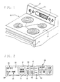
- a free-standing range 10 with four conventional surface units 12 supported from cooktop surface 14 and an oven enclosed by oven door 16.
- Control knobs 18 for the surface units and oven controls comprising a touch switch array 20 are supported from the backsplash comprising glass control panel 22.
- Viewing area 23 on panel 22 exposes an electronic display behind the glass panel aligned with the viewing area opening.
- this display includes a time display 26 comprising two minute and two hour digits separated by a colon, and two similar additional displays 28 and 30.
- Display 26 is active in the clock mode to display real time.
- Display 28 selectively displays cooking time, cleaning time, the start time for a baking cycle and the food temperature when used in combination with a temperature probe (not shown).
- Display 30 selectively displays the oven temperature, the cooking cycle stop time, the selected weight for the load being cooked when operated in the Easy Roast mode, and the broil rate.
- the display area 23 may also include other indicia for conveying information to the user relating to cooking mode and various selections for operating in the Easy Roast mode.
- the touch switch array 20 includes up and down keys 32 and 34, and numerous function keys.
- the function keys include a real time clock setting key 36, a bake key 38, a broil key 40 and timer key 42 and cook time and stop time selection keys 44 and 46 respectively.
- the touch switch array 20 is a membrane touch switch array of generally conventional construction.
- Slewing or slew entry refers to the data entry technique whereby in response to actuation of one of the slew keys the display is incremented or decremented through a sequence of values or characters until the desired value or character appears.
- the general slew entry concept is commonly used in setting digital clocks and selecting temperature set points or power levels for microwave ovens and power levels for cooktop surface units.
- the present invention envisions an improved arrangement for slew entry which enables the user to rapidly arrive at the desired input setting and which is easy to control and comfortable to use.
- the display can be rapidly slewed to a value close to the desired value by continuous actuation of one of the slew keys and increased or decreased in small fixed increments in response to momentary touches of one of the slew keys for fine adjustments or small changes with the display at all times being easily readable to permit the recognition of the desired stopping point.
- the control routines for a microprocessor controlling the display update the display periodically with the update interval, that is, the period between updates being on the order of .25-.65 seconds.
- momentary actuation shall be understood to mean actuation, the duration of which does not exceed one display update interval.
- a momentary actuation changes the display by a discrete amount.
- Continuous actuation shall be understood to mean actuation for a period longer than one update interval.
- the control switches the least significant digit to zero and thereafter the display is periodically changed by an amount evenly divisible by ten. Consequently, the least significant digit remains zero as the more significant digits change.
- the amount for continuously changing the display is ten, resulting in the least significant digit remaining zero and the next higher order digit changing by one unit at the end of each update interval. This permits slewing at a relatively rapid rate for quick convenient response, while providing a display which is much more comfortable to the eye and easier for the user to determine when the displayed value is approximately reached.
- the display when the display is representing time data the least significant digit represents minutes.
- the display changes in one minute increments.
- the display changes in ten minute increments. For example, assume the user wishes to change the setting of the real time clock display 26 from 5:15 to 5:48. The user first actuates the clock function key 36 then touches the up slew key 32. In response to the initial touch of the up key the display changes from 5:15 to 5:16.
- the display then changes to 5:20 and thereafter at each succeeding update interval, the display changes by 10 minute increments for a sequence of 5:20 ⁇ 5:30 ⁇ 5:40 ⁇ 5:50, and upon reaching 5:50 the user releases the key to hold the display at 5:50.
- the final adjustment involves touching the down key momentarily twice to decrement the display in one minute steps to 5:48.
- the same procedure is used to enter starting and stopping times such as for scheduling baking operations except that the cook time and stop time keys are used respectively to initiate those processes and the displays appear at 28 and 30 respectively.
- the nominal update interval is selected to be approximately .45 seconds, that is the display is updated every .45 seconds. This rate provides a sufficiently rapid change of setting for convenient use and provides a display which is comfortable to observe and is easily stopped at the desired setting.
- .45 second update interval is thought to provide a rate which is comfortable to the majority of users, it is also recognized personal preferences may vary somewhat. Therefore, in accordance with a second aspect of this invention, means are provided to permit adjustment of the update interval over a predetermined range. In the illustrative embodiment this range is from .25 seconds to .65 seconds. Specifically, five discrete values are selectable in this range, .25 seconds, .35 seconds, .45 seconds, .55 seconds and .65 seconds.
- the user To change the update interval duration, the user must initiate operation in a special mode designated the Slew Rate mode. Selection of the Slew Rate mode which utilizes both slew keys is valid only when operating in the real time display mode.
- Slew Rate mode Selection of the Slew Rate mode which utilizes both slew keys is valid only when operating in the real time display mode.
- continuous simultaneous actuation of both the up and down keys initiates operation of the Slew Rate mode.
- a number from 1 to 5 is initially displayed, representing the corresponding update interval then being implemented.
- the values 1-5 represent update intervals .65-.25 respectively.
- the display value When in this mode the display value is increased or decreased by touching the up or down key respectively.
- the display changes by one in reponse to each momentary actuation. If continuously actuated, the display will slew by one at the rate set by the then prevailing update interval. Operation in the Slew Rate mode is terminated by touching any one of the functions keys, which changes the
- FIG. 3 A simplified schematic circuit diagram for the display control arrangement of the illustrative embodiment is shown in Fig. 3.
- Microprocessor 50 which in the illustrative embodiment is a chip designated MC68HC05B6 commercially available from Motorola, receives inputs from keyboard matrix 52 on lines labeled L1-L6, S1 and Stop via interface circuitry 54, and supplies out signals to VF display 56 via driver circuits 58 and 60.
- a conventional zero crossing detect circuit 62 synchronizes the internal operation of microprocessor 50 with zero crossings of the 60 HZ AC power signals (not shown) which energizes the various range components as well as the control circuitry.
- a conventional beeper circuit 64 is selectively enabled by microprocessor 50 to provide an audible signal to acknowledge valid touch pad actuations.
- Each touch pad location in keyboard matrix 52 has a pair of output lines uniquely associated with it. Contacts are provided at each touch pad location to selectively couple the associated pair of the output lines L1-L6, S1 and Stop associated with that particular location to ground. Actuation of a touch pad couples both associated lines to ground. For example, referring specifically to touch pad location 1, grounded shorting contact 52a closes across contacts 52b and 52c from lines L1 and L2. Microprocessor 50 indentifies the actuated touch pad location by detecting two grounded input lines. The control function and pair of output lines associated with each of locations 1-16 are shown in Table I, for those keys appearing in the touch pad array in Fig. 2.
- Interface circuitry 54 comprises a pull up resistor 54(a) and a current limiting resistor 54(b) for each output line.
- One end of pull up resistor 52a for each line is connected to a dc voltage source designated V+ and the other end is connected to the corresponding one of output lines L1-L6, S1 and Stop.
- Current limiting resistor 54(b) is connected between the junction of the output line and the pull up resistor and the corresponding one of microprocessor input ports B1-B7 and D2.
- Vacuum fluorescent (VF) display 56 comprises 6 grids or individual displays each comprising 19 controllable segments. Though custom configured to provide the desired display arrangement, the display bottle is of the type commercially available from Futaba and NEC.
- Six grid control outputs from output ports C2-C7 of microprocessor 50 are coupled to six grid control inputs of display 56 via power driver interface circuit 58, which may be a standard driver circuit such as a UDN 6118 available from Sprague.
- the driver circuit is needed to meet the high current requirements of the particular display.
- Driver circuit 60 is a conventional serial to parallel high voltage VF display driver circuit such as a UCN 5812 also commercially available from Sprague.
- Driver circuit 60 receives control inputs from ports A0, A1, TDO and SCLK of microprocessor 50.
- Port TDO provides segment control data in serial form for the 19 controlled display segments.
- Port SCLK provides clock signals and ports A0 and A1 provide enable and strobe signals respectively.
- Microprocessor 72 is customized to perform the display control functions in accordance with this invention by permanently configuring the read only memory (ROM) of microprocessor 72 to implement predetermined control instructions.
- Figs. 4-7 are flow diagrams which illustrate display control routines incorporating the control program of microprocessor 72 for the illustrative embodiment of the present invention herein described. From these diagrams one of ordinary skill in the programming art can prepare a set of control instructions for permanent storage in the ROM of microprocessor 72. For the sake of simplicity and brevity the control routines to follow will be described with respect only to implementation of the set point selection and display control algorithms of the present invention. It should be understood that in addition to these control functions there may be other control functions relative to other operations of the appliance to be performed in conjunction with other operating characteristics of the appliance. Instructions for carrying out the routines described in the diagrams may be interleaved with instructions and routines for other control functions which are not part of the present invention.
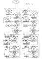
- Fig. 4 a flow diagram illustrates the Time routine, the control routine for entering time data in response to actuation of the clock key and the up and down slew pads.
- the purpose of this routine is to increment or decrement the real time display 26 (Fig. 2) in response to user actuation of the up and down slew keys 32 and 34. Specifically, the display is changed by 1 minute units in response to momentary actuations of the up and down keys. In response to continuous actuation, the display responds to the initial touch in the same manner as the hereinbefore described response to a momentary touch.
- the least significant digit in the minute display is switched to zero and the display is thereafter changed in 10 minute amounts thereby changing the next higher order digit by one unit increments at a predetermined rate for as long as the slew pad remains actuated.
- This predetermined rate is established by the value of the variable designated Slew Rate.
- This routine is entered in response to user actuation of the clock touch pad.
- inquiries 102 and 104 determine whether an up slew pad or a down slew pad has been touched respectively.
- the least significant digit representing minutes represented by the variable MIN is incremented by 1 (Block 106).
- Inquiry 108 determines whether the new value of the minutes variable is greater than 59 minutes. If not, the display is immediately updated (Block 110). If the value exceeds 59, the hours portion of the display is incremented by and the minutes portion is reset to 0 (Block 112).
- Next Inquiry 114 determines if the value of the hours variable exceeds 12.
- Inquiry 118 determines if the slew pad remains touched. If yes, Inquiry 120 determines whether an update interval, of duration represented by the variable Slew Rate in seconds, has elapsed. If not, the program returns to Inquiry 118 and loops between 118 and 120 until the slew pad is released or the update interval has elapsed. If the slew pad is released before the interval has elapsed, the program merely returns to the main control program.
- the value of the minutes interval is rounded down to a next lowest value evenly divisible by 10 and then increased by 10 (Block 122). This switches the least significant digit of the display to 0 and increments the next significant digit by 1.
- the hours variable is incremented when the minutes exceed 60 and the minutes are reset to 0 and the hours variable is reset to 0 when it exceeds 12 (Inquiries 124 and 126 and Blocks 128 and 130).
- the display is then updated (Block 132) and Inquiries 134 and 136 again wait for either the slew pad to be released or for the next control update interval to elapse.
- the minutes display is incremented by 10 (Block 138) and the program returns to Inquiry 124 to repeat Inquiries in Blocks 124-138 until the slew pad is released. This portion of the program continues to update the display in increments of 10 at the end of each update interval until the slew pad is released. Upon release of the slew pad the program returns to the main control program.
- the minutes variable (MIN) is decremented by 1 (Block 140).
- Inquiries 142 and 144 and Blocks 146 and 148 make appropriate adjustments in the minutes and hours display to reflect the 1 minute decrement and the display is updated at Block 150.
- Inquiries 152 and 154 determine if the slew pad remains actuated until the end of the next update interval. If not, the program returns to the main control program. If the pad is still down when the update interval has elapsed, the minutes variable is rounded down to the next value evenly divisible by 10 and decremented by 10 (Block 156).
- Inquiries 158 and 162 and Blocks 160 and 164 make the appropriate adjustments in the minutes and hours variable to reflect the 10 minute decrement and the display is updated (Block 166).
- Inquiries 168 and 170 determine if a slew pad remains actuated until the next control interval elapses. If so, the display is decremented by 10 and the program returns to Inquiry 158 to appropriately adjust the hours and minutes values. The display is again updated and the program then again awaits the elapse of the next occurring update interval or release of the slew pad. This loop continues until the slew pad is released. When the slew pad is released, the program returns to the main control program.
- the above described routine for entering time data is used for updating the real time display. It will be appreciated that a similar routine is used to enter time data for the cook time and stop time displays as well, the difference being essentially that a different display is updated depending upon which function key is actuated by the user to initiate the update process.
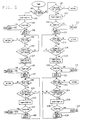
- Temp routine This routine, which is entered in response to user actuation of the Bake key, permits the user to input the desired baking set point temperature for the Bake operating mode.
- the function of this routine is to increase or decrease the temperature display by 5° in response to the discrete momentary actuation of the up or down slew key respectively, and to detect continuous actuation of the up or down slew pad and switch the least significant digit of the temperature display to 0 and increase or decrease the display by 10 at a predetermined rate until the up or down slew pad is released.
- the permissible range for temperature selection is from 150° to 550° F.
- the rate is set by the value of the variable Slew Rate which establishes the duration of each update interval.
- Inquiries 180 and 182 determine if an up or down slew pad has been touched respectively.
- the temperature variable TEMP is incremented by 5° (Block 184) and Inquiry 186 determines if the new value is greater than the maximum permitted value of 550°. If yes, the set point display is set to the maximum of 550° (Block 187), and the display is updated (Block 188). If the new value is not greater than 550°, the display is simply updated (Block 188).
- Inquiries 190 and 192 determine if the slew pad remains actuated until the end of the update interval. If not, the program returns to the main control program.
- the temperature value is rounded down to the nearest value evenly divisible by 10 and incremented by 10 (Block 194).
- Inquiry 195 and Block 196 again limit the display to the maximum of 550°, and the display is updated (Block 197).
- Inquires 198 and 200 again determine if the slew pad remains actuated. If the pad remains actuated until the next update interval elapses, Temp is again incremented by 10 (Block 202).
- Inquiry 204 and Block 205 again limit the maximum temperature to 550°, the display is updated (Block 206), and the program loops back to Inquiry 198 to determine if the slew pad remains actuated.
- the program as illustrated by Inquiries 198, 200, 204 and Blocks 202, 205 and 206 continue to update the temperature display in 10° increments at the expiration of each update interval until the maximum is reached or the slew pad is released. On release of the slew pad the program returns to the main control program.
- Inquiry 210 and Block 211 limit the display to the minimum selectable value of 150° and the display is updated (Block 212).
- Inquiries 214 and 216 determine if the slew pad remains actuated until the next update interval has elapsed. If not, the program returns to the main control program. If the slew pad remains actuated, Temp is rounded down to a value evenly divisible by 10 and decremented by 10° (Block 218). The temperature display is again limited to a minimum of 150° (Inquiry 219 and Block 220) and the display is updated (Block 221).
- Inquiries 222 and 224 determine if the slew pad continues to be actuated through the end of the next update interval. If not, the program returns to the main control program. If the slew pad remains actuated, the temperature display is decremented by 10 (Block 226). Inquiry 228 and Block 229 ensure that Temp is not less than 150° and the display is updated (Block 230). The program as illustrated by Inquiries 222, 224 and 228 and Blocks 226, 229 and 230 continue to decrement the temperature display by 10° at the end of each update interval as long as the slew pad remains actuated or the minimum temperature is reached.
- the Temp routine described above is used to update the temperature value when operating in the Bake mode.
- a similar routine is used to update the temperature display when operating in the Temp Cook mode utilizing a temperature probe in the oven. The difference being that a different portion of the main display is controlled in response to actuation of that function key.
- the slew rate mode is selected in the illustrative embodiment by simultaneous actuation by the user of both the up and down slew keys for a period of four seconds.
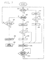
- the SR mode routine illustrated in Fig. 6 detects user selection of the slew rate mode. It will be recalled that the user can initiate the slew rate mode to change the slew rate only when the control is operating in the real time clock mode. This routine is entered each pass through the control routine for operation in the clock mode to detect selection of the slew rate selection mode.
- the time variable T used in monitoring the duration of key actuation, is set to 0 (Block 240). Inquiries 242 and 244 look for actuation of the up key and down key respectively. If both are simultaneously actuated, Inquiry 246 determines if the four second time period has elapsed. If not, the time variable T is incremented (Block 248) and the program returns to Inquiry 242 to repeat the loop until either at least one key is released or the 4 second period elapses. If both keys remain actuated for the four second period, the program then proceeds to display the current slew rate value represented by the variable SR (Block 250).
- the SR variable will equal one of the integer values 1 thru 5 which represent update interval durations of .65, .55, .45, .35 and .25 seconds respectively.
- Inquiries 252 and 254 then hold the program in this portion of the routine until both up and down keys have been released. Upon release of both keys, the program proceeds (Block 256) to the SR update routine (Fig. 7).
- the function of the SR update routine is to increment or decrement the SR variable to enable the user to change the duration of the update interval. This routine is only entered from the SR mode routine, and thus is only entered when the user has selected the slew rate mode by simultaneous actuation of both up and down keys as above described.
- Inquiries 260 and 262 determine if an up or a down slew pad has been touched respectively. If the up pad has been actuated, the SR variable is increased by 1 (Block 264). Inquiry 266 and Block 268 limit the value of SR to the maximum of 5, by returning the display to 1 when the user attempts to increment it beyond 5. Having established the appropriate updated value for SR, the SR display is updated (Block 270) and Inquiry 272 determines if the update interval has elapsed. Upon determining that the update interval has elapsed, the program returns to Inquiry 260 to determine if the slew pad remains touched or has been touched again.
- the slew pad is incremented by 1 in reponse to each momentary actuation of the slew pad and is incremented by 1 continuously at a rate established by the update interval rate if the slew pad remains touched continuously.
- the SR variable is decremented by 1 (Block 274).
- Inquiry 276 and Block 278 limit SR to the minimum value of 1 by reverting SR to 5 when the user attempts to decrement to less than 1. Having established the correct decremented value for SR, the display is updated at 270 and the program proceeds at 272 as described above.
- the update mode is terminated by the touching of any function key other than a slew key. If neither slew pad is touched, Inquiry 280 determines if any other function pad is touched. If so, the variable Slew Rate is updated (Block 282) to reflect the newly selected value for variable SR, that is Slew Rate is set to the corresponding time in seconds for the numerical value of SR and the program returns to the real time clock mode (Block 284).
Landscapes
- Physics & Mathematics (AREA)
- General Physics & Mathematics (AREA)
- Engineering & Computer Science (AREA)
- Automation & Control Theory (AREA)
- Electric Ovens (AREA)
- Input From Keyboards Or The Like (AREA)
- Control Of Indicators Other Than Cathode Ray Tubes (AREA)
Claims (9)
- Dateneingabe- und Displaysteueranordnung, enthaltend:eine elektronische Displayeinrichtung (23) mit mehreren Ziffern, die eine niederwertigste Ziffer und eine oder mehrere Ziffern höherer Ordnung aufweisen zum Darstellen numerischer Betriebsdaten,eine Dateneingabeeinrichtung (20), die mehrere vom Benutzer betätigbare Tasten (32-46) einschließliche einer Aufwärtstaste (32) und einer Abwärtstaste (34) aufweist,eine Displaysteuereinrichtung (50, 54, 58, 60), die auf die Dateneingabeeinrichtung (20) anspricht,wobei die Displaysteuereinrichtung (50, 54, 58, 60) eine Aktualisierungseinrichtung (50) aufweist zum periodischen Aktualisieren der Displayeinrichtung (23) an regelmäßigen Aktualisierungs-Intervallen von vorbestimmter Dauer als Antwort auf eine Betätigung der Aufwärtstaste (32) oder der Abwärtstaste (34), dadurch gekennzeichnet, daß die Aktualisierungseinrichtung (50) die Funktion hat,die Displayeinrichtung (23) um eine erste Größe zu vergrößern oder zu verkleinern als Antwort auf jede Anfangsbetätigung der Aufwärtstaste (32) bzw. der Abwärtstaste (34) und als Antwort auf eine kontinuierliche Betätigung, um die niederwertigste Ziffer auf Null zu schalten und danach die Displayeinrichtung (23) um eine zweite Größe, die glatt durch Zehn teilbar ist, am Ende von jedem nachfolgenden Aktualisierungsintervall zu vergrößern oder zu verkleinern, unabhängig von dem Anfangswert der Displayeinrichtung, solange die Aufwärtstaste (32) oder die Abwärtstaste (34) kontinuierlich betätigt bleibt, wodurch die Diplayeinrichtung (23) in relativ kleinen Inkrementen verändert wird, wenn eine Aufwärtstaste (32) oder Abwärtstaste (34) für eine Dauer betätigt wird, die kein Display-Aktualisierungsintervall überschreitet, und in größeren Inkrementen verändert wird, wobei die dargestellten Werten glatt durch Zehn teilbar sind, wenn eine Aufwärtstaste (32) oder Abwärtstaste (34) kontinuierlich betätigt wird.
- Steueranordnung nach Anspruch 1, wobei die numerischen Betriebsdaten Zeitdaten (26, 28) aufweisen, die niederwertigste Ziffer Minuten darstellt und die Displayeinrichtung (23) in Ein-Minuten-Inkrementen erhöht oder vermindert wird als Antwort auf eine Betätigung für eine Dauer, die kein Display-Aktualisierungsintervall überschreitet, und in Zehn-Minuten-Inkrementen, wenn die Aufwärtstaste (32) oder die Abwärtstaste (34) kontinuierlich betätigt bleibt.
- Steueranordnung nach Anspruch 1 oder 2, wobei die numerischen Betriebsdaten Temperaturdaten (30) aufweisen, wobei die niederwertigste Ziffer Grad darstellt, und wobei die Displayeinrichtung (23) in Fünf-Grad-Inkrementen erhöht oder erniedrigt wird als Antwort auf die Betätigung von einer der Aufwärtstasten (32) bzw. der Abwärtstasten (34) für eine Dauer, die kein Display-Aktualisierungsintervall überschreitet, und periodisch erhöht oder erniedrigt wird in Zehn-Grad-Inkrementen als Antwort auf ihre kontinuierliche Betätigung.
- Steueranordnung nach Anspruch 1, 2 oder 3, wobei erste und zweite Funktionstasten vorgesehen sind und Zeit (42, 44, 46) und Temperatur (38, 40) wählende Tasten aufweisen, wobei die Displayeinrichtung (23) die Funktion hat, numerische Betriebsdaten anzuzeigen, die Zeitdaten darstellen, wenn die Zeitwähltaste (42, 44, 46) betätigt ist, wobei die ersten und zweiten Größen eine Minute bzw. zehn Minuten sind, und die Displayeinrichtung (23) die Funktion hat, numerische Betriebsdaten anzuzeigen, die Temperaturdaten darstellen, wenn die Temperaturwähltaste (38, 40) betätigt ist, wobei die ersten und zweiten Größen fünf Grad bzw. zehn Grad sind.
- Steueranordnung nach einem der vorstehenden Ansprüche, wobei das Aktualisierungsintervall eine Dauer von etwa 0,45 Sekunden hat.
- Steueranordnung nach einem der Ansprüche 1 - 5, wobei ferner eine Einrichtung (32, 34) zum Ändern der Dauer des Aktualisierungsintervalls vorgesehen ist.
- Steueranordnung nach Anspruch 6, wobei ferner eine Einrichtung (32, 34) zum Wählen der Dauer des Aktualisierungsintervalls aus einem Bereich von Intervallwerten vorgesehen ist, die zwischen 0,25 Sekunden und 0,65 Sekunden variieren.
- Steueranordnung nach Anspruch 6, wobei ferner eine Einrichtung (32, 34) zum Wählen der Dauer des Aktualisierungsintervalls aus einem Bereich von diskreten Intervallwerten vorgesehen ist, der 0,45 Sekunden enthält.
- Steueranordnung nach Anspruch 8, wobei der Bereich diskreter Intervallwerte ferner 0,25 Sekunden, 0,35 Sekunden, 0,45 Sekunden, 0,55 Sekunden und 0,65 Sekunden enthält.
Applications Claiming Priority (2)
| Application Number | Priority Date | Filing Date | Title |
|---|---|---|---|
| US07/267,501 US4902878A (en) | 1988-11-04 | 1988-11-04 | Data entry and control arrangement for an appliance |
| US267501 | 1988-11-04 |
Publications (3)
| Publication Number | Publication Date |
|---|---|
| EP0367626A2 EP0367626A2 (de) | 1990-05-09 |
| EP0367626A3 EP0367626A3 (de) | 1992-03-04 |
| EP0367626B1 true EP0367626B1 (de) | 1996-03-06 |
Family
ID=23019054
Family Applications (1)
| Application Number | Title | Priority Date | Filing Date |
|---|---|---|---|
| EP89311429A Expired - Lifetime EP0367626B1 (de) | 1988-11-04 | 1989-11-03 | Dateneingabe und Steuereinrichtung, zum Beispiel für ein Gerät |
Country Status (5)
| Country | Link |
|---|---|
| US (1) | US4902878A (de) |
| EP (1) | EP0367626B1 (de) |
| JP (1) | JP3251936B2 (de) |
| CA (1) | CA1326309C (de) |
| DE (1) | DE68925861T2 (de) |
Families Citing this family (19)
| Publication number | Priority date | Publication date | Assignee | Title |
|---|---|---|---|---|
| JPH0792719B2 (ja) * | 1989-03-17 | 1995-10-09 | アンリツ株式会社 | データ入力装置 |
| DE69322368T2 (de) * | 1992-12-25 | 1999-06-02 | Omron Corp., Kyoto | Steuervorrichtung |
| DE4336438C1 (de) * | 1993-10-26 | 1994-11-24 | Reinhausen Maschf Scheubeck | Verfahren zur Parametrierung eines digitalen Spannungsreglers, insbesondere zur Steuerung eines Transformators mit Stufenschalter |
| JP3483927B2 (ja) * | 1994-03-30 | 2004-01-06 | 三菱電機エンジニアリング株式会社 | インバータ運転指令装置 |
| US5703774A (en) * | 1995-05-11 | 1997-12-30 | The Boeing Company | Variable slew selector switch system |
| US5680312A (en) * | 1995-06-07 | 1997-10-21 | Zexel Corporation | Method and apparatus for selecting a destination in a vehicle navigation system |
| US5805085A (en) * | 1996-07-26 | 1998-09-08 | United Microelectronics Corporation | Apparatus and method for scanning a key matrix |
| US6845290B1 (en) * | 2000-05-02 | 2005-01-18 | General Electric Company | System and method for controlling a dryer appliance |
| US7128466B2 (en) * | 2001-07-09 | 2006-10-31 | Ewig Industries Co., Ltd. | Dual thermometer system |
| DE10228237B9 (de) * | 2002-06-25 | 2004-07-22 | Diehl Ako Stiftung & Co. Kg | Bedienungseinrichtung für einen Kochherd und Verfahren zur Bedienung derselben |
| KR20040027147A (ko) * | 2002-09-27 | 2004-04-01 | 삼성전자주식회사 | 복합 조리기기 |
| US6967314B2 (en) * | 2003-06-26 | 2005-11-22 | Maytag Corporation | Programmable power level control for a cooking appliance |
| DE102004020824A1 (de) | 2004-04-28 | 2005-12-01 | BSH Bosch und Siemens Hausgeräte GmbH | Stellvorrichtung mit einem zumindest zweidimensionalen Sen-sorbereich |
| US20070028191A1 (en) * | 2005-08-01 | 2007-02-01 | Kyocera Mita Corporation | Electronic device and storage medium for control program thereof |
| JP4892906B2 (ja) * | 2005-09-16 | 2012-03-07 | パナソニック株式会社 | 加熱調理器 |
| JP5122544B2 (ja) * | 2009-10-30 | 2013-01-16 | 京セラドキュメントソリューションズ株式会社 | 数値入力装置及び該数値入力装置を備えた画像形成装置 |
| JP5010714B2 (ja) * | 2010-05-21 | 2012-08-29 | 株式会社東芝 | 電子機器、入力制御プログラム、及び入力制御方法 |
| KR101237472B1 (ko) * | 2011-12-30 | 2013-02-28 | 삼성전자주식회사 | 전자 장치 및 그의 제어 방법 |
| US20160223205A1 (en) * | 2015-01-30 | 2016-08-04 | Oscar Yonghwan CHOI | Timer device for stove |
Family Cites Families (15)
| Publication number | Priority date | Publication date | Assignee | Title |
|---|---|---|---|---|
| US4011428A (en) * | 1975-03-24 | 1977-03-08 | Essex International, Inc. | Microwave oven timer and control circuit |
| US4169222A (en) * | 1977-07-26 | 1979-09-25 | Rangaire Corporation | Induction cook-top system and control |
| US4158759A (en) * | 1977-09-16 | 1979-06-19 | Teccor Electronics, Inc. | Microwave oven control system |
| JPS54149040A (en) * | 1978-05-12 | 1979-11-21 | Matsushita Electric Ind Co Ltd | Heating device |
| CA1116729A (en) * | 1978-07-28 | 1982-01-19 | Stephen E. Heeger | Sequence controller with microprocessor |
| GB2120815B (en) * | 1979-02-05 | 1984-08-15 | Turnright Controls | Improvements in or relating to programmable timing apparatus |
| US4308443A (en) * | 1979-05-01 | 1981-12-29 | Rangaire Corporation | Induction cook-top with improved touch control |
| AU523649B2 (en) * | 1979-10-18 | 1982-08-05 | Matsushita Electric Industrial Co., Ltd. | Heating apparatus safety device using voice synthesizer |
| JPS5747133A (en) * | 1980-09-05 | 1982-03-17 | Matsushita Electric Ind Co Ltd | Heating apparatus |
| US4372054A (en) | 1981-02-02 | 1983-02-08 | Emhart Industries, Inc. | Method and means for programming the operation of an apparatus |
| US4488148A (en) * | 1982-02-19 | 1984-12-11 | Becton, Dickinson And Company | Combination switching and display electronic modular control unit |
| US4527049A (en) * | 1984-02-09 | 1985-07-02 | Raytheon Company | Microprocessor controlled electric range |
| GB2155211B (en) * | 1984-02-21 | 1988-01-27 | Toshiba Kk | Cooking apparatus |
| JPS60253738A (ja) * | 1984-05-29 | 1985-12-14 | Toshiba Corp | 加熱調理装置 |
| US4725948A (en) * | 1985-11-19 | 1988-02-16 | Hamilton Standard Controls, Inc. | Heating appliance control system |
-
1988
- 1988-11-04 US US07/267,501 patent/US4902878A/en not_active Expired - Lifetime
-
1989
- 1989-07-31 CA CA000607116A patent/CA1326309C/en not_active Expired - Fee Related
- 1989-11-01 JP JP28318189A patent/JP3251936B2/ja not_active Expired - Lifetime
- 1989-11-03 EP EP89311429A patent/EP0367626B1/de not_active Expired - Lifetime
- 1989-11-03 DE DE68925861T patent/DE68925861T2/de not_active Expired - Fee Related
Also Published As
| Publication number | Publication date |
|---|---|
| DE68925861D1 (de) | 1996-04-11 |
| EP0367626A2 (de) | 1990-05-09 |
| JPH02178819A (ja) | 1990-07-11 |
| US4902878A (en) | 1990-02-20 |
| DE68925861T2 (de) | 1996-11-07 |
| JP3251936B2 (ja) | 2002-01-28 |
| CA1326309C (en) | 1994-01-18 |
| EP0367626A3 (de) | 1992-03-04 |
Similar Documents
| Publication | Publication Date | Title |
|---|---|---|
| EP0367626B1 (de) | Dateneingabe und Steuereinrichtung, zum Beispiel für ein Gerät | |
| US4625086A (en) | Cooking apparatus capable of displaying the ratio of elapsed cooking time to pre-set time | |
| CA2314411C (en) | Program control and display system for a cooking appliance | |
| EP3440890B1 (de) | Gerät mit elektrovibrationsbenutzerfeedback bei einer berührungstafelschnittstelle | |
| EP1733362B1 (de) | Herd | |
| US5373142A (en) | Control system for a heating apparatus | |
| KR960014015B1 (ko) | 전력제어가 개선된 쿡톱 기구 | |
| US8035063B2 (en) | Electronic power control for cooktop heaters | |
| JP2878698B2 (ja) | 調理用ガラスセラミック板を有する装置の電力制御システム | |
| EP0762060A1 (de) | Abwärtszähler zum Vorheizen eines Ofens | |
| WO2014086566A1 (en) | A cooking hob including a user interface | |
| US6005229A (en) | Cooking oven including a convection heat source and a microwave heat source | |
| EP0291302B1 (de) | Elektroherd | |
| US20080217320A1 (en) | Cooking Appliance with Touch-Sensitive Control Strip | |
| EP3767181B1 (de) | Haushaltsgerät und verfahren zur steuerung eines haushaltsgeräts | |
| EP3001108B1 (de) | Elektonisches haushaltsgerät | |
| JP2552303B2 (ja) | 自動焙焼装置 | |
| US6255629B1 (en) | Device for switching an electric heater | |
| JPH06237853A (ja) | 炊飯器 | |
| EP4486059A1 (de) | Kochfeld | |
| KR101003614B1 (ko) | 전기 호브 | |
| KR20010003923A (ko) | 전기밥솥의 예약시간 설정방법 | |
| KR100539548B1 (ko) | 조리기기에서 요리시간 제어 방법 | |
| JP2503843B2 (ja) | 高周波電磁調理器 | |
| JPH05322181A (ja) | 加熱調理器 |
Legal Events
| Date | Code | Title | Description |
|---|---|---|---|
| PUAI | Public reference made under article 153(3) epc to a published international application that has entered the european phase |
Free format text: ORIGINAL CODE: 0009012 |
|
| AK | Designated contracting states |
Kind code of ref document: A2 Designated state(s): DE FR GB IT |
|
| PUAL | Search report despatched |
Free format text: ORIGINAL CODE: 0009013 |
|
| AK | Designated contracting states |
Kind code of ref document: A3 Designated state(s): DE FR GB IT |
|
| 17P | Request for examination filed |
Effective date: 19920824 |
|
| 17Q | First examination report despatched |
Effective date: 19940216 |
|
| GRAH | Despatch of communication of intention to grant a patent |
Free format text: ORIGINAL CODE: EPIDOS IGRA |
|
| GRAA | (expected) grant |
Free format text: ORIGINAL CODE: 0009210 |
|
| AK | Designated contracting states |
Kind code of ref document: B1 Designated state(s): DE FR GB IT |
|
| ET | Fr: translation filed | ||
| REF | Corresponds to: |
Ref document number: 68925861 Country of ref document: DE Date of ref document: 19960411 |
|
| ITF | It: translation for a ep patent filed | ||
| PLBE | No opposition filed within time limit |
Free format text: ORIGINAL CODE: 0009261 |
|
| STAA | Information on the status of an ep patent application or granted ep patent |
Free format text: STATUS: NO OPPOSITION FILED WITHIN TIME LIMIT |
|
| 26N | No opposition filed | ||
| REG | Reference to a national code |
Ref country code: GB Ref legal event code: IF02 |
|
| PGFP | Annual fee paid to national office [announced via postgrant information from national office to epo] |
Ref country code: FR Payment date: 20021017 Year of fee payment: 14 |
|
| PGFP | Annual fee paid to national office [announced via postgrant information from national office to epo] |
Ref country code: GB Payment date: 20021030 Year of fee payment: 14 |
|
| PGFP | Annual fee paid to national office [announced via postgrant information from national office to epo] |
Ref country code: DE Payment date: 20021202 Year of fee payment: 14 |
|
| PG25 | Lapsed in a contracting state [announced via postgrant information from national office to epo] |
Ref country code: GB Free format text: LAPSE BECAUSE OF NON-PAYMENT OF DUE FEES Effective date: 20031103 |
|
| PG25 | Lapsed in a contracting state [announced via postgrant information from national office to epo] |
Ref country code: DE Free format text: LAPSE BECAUSE OF NON-PAYMENT OF DUE FEES Effective date: 20040602 |
|
| GBPC | Gb: european patent ceased through non-payment of renewal fee |
Effective date: 20031103 |
|
| PG25 | Lapsed in a contracting state [announced via postgrant information from national office to epo] |
Ref country code: FR Free format text: LAPSE BECAUSE OF NON-PAYMENT OF DUE FEES Effective date: 20040730 |
|
| REG | Reference to a national code |
Ref country code: FR Ref legal event code: ST |
|
| PG25 | Lapsed in a contracting state [announced via postgrant information from national office to epo] |
Ref country code: IT Free format text: LAPSE BECAUSE OF NON-PAYMENT OF DUE FEES;WARNING: LAPSES OF ITALIAN PATENTS WITH EFFECTIVE DATE BEFORE 2007 MAY HAVE OCCURRED AT ANY TIME BEFORE 2007. THE CORRECT EFFECTIVE DATE MAY BE DIFFERENT FROM THE ONE RECORDED. Effective date: 20051103 |