EP0367648B1 - Schweissverfahren und Schweissvorrichtung, um aus der Entfernung eine Muffe in ein Rohr, insbesondere innerhalb eines Dampferzeugers eines Kernkraftwerkes, einzuschweissen - Google Patents
Schweissverfahren und Schweissvorrichtung, um aus der Entfernung eine Muffe in ein Rohr, insbesondere innerhalb eines Dampferzeugers eines Kernkraftwerkes, einzuschweissen Download PDFInfo
- Publication number
- EP0367648B1 EP0367648B1 EP89402840A EP89402840A EP0367648B1 EP 0367648 B1 EP0367648 B1 EP 0367648B1 EP 89402840 A EP89402840 A EP 89402840A EP 89402840 A EP89402840 A EP 89402840A EP 0367648 B1 EP0367648 B1 EP 0367648B1
- Authority
- EP
- European Patent Office
- Prior art keywords
- welding
- tube
- bush
- receiver tube
- welded
- Prior art date
- Legal status (The legal status is an assumption and is not a legal conclusion. Google has not performed a legal analysis and makes no representation as to the accuracy of the status listed.)
- Expired - Lifetime
Links
- 238000003466 welding Methods 0.000 title claims description 78
- 238000000034 method Methods 0.000 title claims description 19
- 230000003287 optical effect Effects 0.000 claims description 47
- 239000000835 fiber Substances 0.000 claims description 44
- 239000013307 optical fiber Substances 0.000 claims description 26
- 239000004606 Fillers/Extenders Substances 0.000 claims description 12
- 210000004027 cell Anatomy 0.000 description 24
- XLYOFNOQVPJJNP-UHFFFAOYSA-N water Substances O XLYOFNOQVPJJNP-UHFFFAOYSA-N 0.000 description 14
- 239000012530 fluid Substances 0.000 description 7
- 235000021183 entrée Nutrition 0.000 description 5
- 239000007789 gas Substances 0.000 description 5
- 230000008439 repair process Effects 0.000 description 5
- 238000002347 injection Methods 0.000 description 4
- 239000007924 injection Substances 0.000 description 4
- 230000009471 action Effects 0.000 description 3
- 239000011324 bead Substances 0.000 description 3
- 230000002950 deficient Effects 0.000 description 3
- 238000006073 displacement reaction Methods 0.000 description 3
- VYPSYNLAJGMNEJ-UHFFFAOYSA-N Silicium dioxide Chemical compound O=[Si]=O VYPSYNLAJGMNEJ-UHFFFAOYSA-N 0.000 description 2
- 240000008042 Zea mays Species 0.000 description 2
- 230000000712 assembly Effects 0.000 description 2
- 238000000429 assembly Methods 0.000 description 2
- 230000005540 biological transmission Effects 0.000 description 2
- 238000002788 crimping Methods 0.000 description 2
- 239000000446 fuel Substances 0.000 description 2
- CPBQJMYROZQQJC-UHFFFAOYSA-N helium neon Chemical compound [He].[Ne] CPBQJMYROZQQJC-UHFFFAOYSA-N 0.000 description 2
- 238000007689 inspection Methods 0.000 description 2
- 238000009434 installation Methods 0.000 description 2
- 230000002285 radioactive effect Effects 0.000 description 2
- 238000007789 sealing Methods 0.000 description 2
- 239000008400 supply water Substances 0.000 description 2
- 229910052779 Neodymium Inorganic materials 0.000 description 1
- 230000004888 barrier function Effects 0.000 description 1
- 238000005452 bending Methods 0.000 description 1
- 230000008859 change Effects 0.000 description 1
- 239000012141 concentrate Substances 0.000 description 1
- 238000011109 contamination Methods 0.000 description 1
- 238000001816 cooling Methods 0.000 description 1
- 239000000498 cooling water Substances 0.000 description 1
- 238000005260 corrosion Methods 0.000 description 1
- 230000007797 corrosion Effects 0.000 description 1
- 230000007547 defect Effects 0.000 description 1
- 238000010586 diagram Methods 0.000 description 1
- 238000010304 firing Methods 0.000 description 1
- 238000010438 heat treatment Methods 0.000 description 1
- 239000011261 inert gas Substances 0.000 description 1
- 238000012423 maintenance Methods 0.000 description 1
- 230000004048 modification Effects 0.000 description 1
- 238000012986 modification Methods 0.000 description 1
- QEFYFXOXNSNQGX-UHFFFAOYSA-N neodymium atom Chemical compound [Nd] QEFYFXOXNSNQGX-UHFFFAOYSA-N 0.000 description 1
- 230000002093 peripheral effect Effects 0.000 description 1
- 230000008569 process Effects 0.000 description 1
- 230000001681 protective effect Effects 0.000 description 1
- 238000010926 purge Methods 0.000 description 1
- 230000008054 signal transmission Effects 0.000 description 1
- 239000000377 silicon dioxide Substances 0.000 description 1
- 125000006850 spacer group Chemical group 0.000 description 1
- 238000001228 spectrum Methods 0.000 description 1
- 238000003860 storage Methods 0.000 description 1
- 210000001578 tight junction Anatomy 0.000 description 1
Images




Classifications
-
- B—PERFORMING OPERATIONS; TRANSPORTING
- B23—MACHINE TOOLS; METAL-WORKING NOT OTHERWISE PROVIDED FOR
- B23K—SOLDERING OR UNSOLDERING; WELDING; CLADDING OR PLATING BY SOLDERING OR WELDING; CUTTING BY APPLYING HEAT LOCALLY, e.g. FLAME CUTTING; WORKING BY LASER BEAM
- B23K26/00—Working by laser beam, e.g. welding, cutting or boring
- B23K26/08—Devices involving relative movement between laser beam and workpiece
- B23K26/10—Devices involving relative movement between laser beam and workpiece using a fixed support, i.e. involving moving the laser beam
- B23K26/103—Devices involving relative movement between laser beam and workpiece using a fixed support, i.e. involving moving the laser beam the laser beam rotating around the fixed workpiece
- B23K26/106—Devices involving relative movement between laser beam and workpiece using a fixed support, i.e. involving moving the laser beam the laser beam rotating around the fixed workpiece inside the workpiece
-
- B—PERFORMING OPERATIONS; TRANSPORTING
- B23—MACHINE TOOLS; METAL-WORKING NOT OTHERWISE PROVIDED FOR
- B23K—SOLDERING OR UNSOLDERING; WELDING; CLADDING OR PLATING BY SOLDERING OR WELDING; CUTTING BY APPLYING HEAT LOCALLY, e.g. FLAME CUTTING; WORKING BY LASER BEAM
- B23K26/00—Working by laser beam, e.g. welding, cutting or boring
-
- B—PERFORMING OPERATIONS; TRANSPORTING
- B23—MACHINE TOOLS; METAL-WORKING NOT OTHERWISE PROVIDED FOR
- B23K—SOLDERING OR UNSOLDERING; WELDING; CLADDING OR PLATING BY SOLDERING OR WELDING; CUTTING BY APPLYING HEAT LOCALLY, e.g. FLAME CUTTING; WORKING BY LASER BEAM
- B23K26/00—Working by laser beam, e.g. welding, cutting or boring
- B23K26/02—Positioning or observing the workpiece, e.g. with respect to the point of impact; Aligning, aiming or focusing the laser beam
-
- B—PERFORMING OPERATIONS; TRANSPORTING
- B23—MACHINE TOOLS; METAL-WORKING NOT OTHERWISE PROVIDED FOR
- B23K—SOLDERING OR UNSOLDERING; WELDING; CLADDING OR PLATING BY SOLDERING OR WELDING; CUTTING BY APPLYING HEAT LOCALLY, e.g. FLAME CUTTING; WORKING BY LASER BEAM
- B23K26/00—Working by laser beam, e.g. welding, cutting or boring
- B23K26/20—Bonding
- B23K26/21—Bonding by welding
- B23K26/24—Seam welding
- B23K26/244—Overlap seam welding
-
- B—PERFORMING OPERATIONS; TRANSPORTING
- B23—MACHINE TOOLS; METAL-WORKING NOT OTHERWISE PROVIDED FOR
- B23K—SOLDERING OR UNSOLDERING; WELDING; CLADDING OR PLATING BY SOLDERING OR WELDING; CUTTING BY APPLYING HEAT LOCALLY, e.g. FLAME CUTTING; WORKING BY LASER BEAM
- B23K26/00—Working by laser beam, e.g. welding, cutting or boring
- B23K26/20—Bonding
- B23K26/21—Bonding by welding
- B23K26/24—Seam welding
- B23K26/28—Seam welding of curved planar seams
Definitions
- the invention relates to the remote welding of a sleeve into a tube. It applies in particular to the restoration of the sealing of the steam generator tubes of a pressurized water nuclear reactor.
- the steam generators of such power plants generally comprise a bundle made up of a very large number of small diameter tubes bent into a U and fixed at each of their ends by crimping in a very thick tubular plate.
- the part of the steam generator located below the tube plate constitutes a water box in a first part of which the "primary" water under pressure coming from the reactor vessel is distributed in the tubes of the bundle.
- the water having circulated in the tubes is recovered, to be returned, by a pipe of the primary circuit of the reactor, in the tank containing the core constituted by the fuel assemblies ensuring the heating of the water under pressure.
- the steam generator supply water comes into contact with the outside surface of the bundle tubes, in the part of the steam generator located above the tube plate, to be transformed into steam and this steam is sent to the turbine associated with the nuclear reactor.
- the walls of the bundle tubes therefore constitute a barrier between the pressurized water constituting the primary fluid of the reactor and the supply water constituting the secondary fluid.
- the primary fluid which comes into contact with the fuel assemblies and the internal structures of the reactor vessel contains radioactive products in more or less quantity. It is therefore advisable to avoid bringing the primary fluid into contact with the secondary fluid, the contamination of which could have very harmful consequences. This requires avoiding as much as possible the appearance of leaks through the walls of the tubes of the bundle of the steam generator and repairing as quickly as possible and efficiently the tubes whose wall is pierced.
- a method for repairing the tubes of the bundle of a steam generator by sleeving these tubes, at the level of the defect causing a loss of tightness is known.
- a sleeve with an outside diameter slightly less than the inside diameter of the tube to be repaired and of a length sufficient to cover the defective zone is introduced into the tube, through the entry face of the tube plate on which the ends of the tubes. It is placed there so as to be flush with the entry face of the tubular plate for the tubes situated in the central part thereof, or at mid-thickness of the tubular plate for the tubes situated at the periphery thereof. It is then fixed inside the tube so as to make two tight junctions between it and the tube on either side of the defective zone.
- US-A-4,694,136 describes a device for performing such welding.
- This device includes an optical welding head installed in the tube and a power laser located outside the water box of the steam generator.
- the beam is transported by optical means by air, between the laser located outside the water box of the steam generator and the welding head.
- This device requires the installation and installation at the foot of the steam generator of bulky equipment with all of its fluid supplies (electrical supplies, water from cooling).
- the power laser must be installed very close to the inspection hatch of the water box, an area subjected to a level of irradiation almost as high as inside the water box. We thought of moving the laser away from the inspection hatch, but this distance cannot be extended too much without complicating the aiming problems which quickly become unacceptable.
- the welding head used has a drawback related to the fact that the focal distance is kept constant and equal to the firing distance by a ball stop and an application spring: this system generates friction, from - cuts and vibrations damaging to the quality of the weld produced.
- the present invention provides a method for welding a sleeve in a steam generator tube using an energy source located at a significant distance from the steam generator, for example outside the reactor building containing it ci, and a device allowing the implementation of this method.
- Welding requires making a connection between on the one hand a receiving tube which is for example a tube to be repaired T and which has an axis A, and on the other hand a welding sleeve M which has a wall S and which has been previously placed in this tube.
- a receiving tube which is for example a tube to be repaired T and which has an axis A
- a welding sleeve M which has a wall S and which has been previously placed in this tube.
- An impact point rotation operation is carried out by rotating the optical cell (or at least said optical deflection means (37)) around the axis A of the receiving tube to make the impact point H describe at least one arc on the sleeve to be welded M so as to produce a weld bead.
- This rotation is driven by a motor element such as a motor cell 2 located outside the receiver tube T opposite the entry thereof.
- This drive element is mechanically connected to said optical deflection means by a tubular extension assembly.
- the latter consists of a flexible sheath 19, a rigid end piece 20 and a cylindrical part 23. It is arranged in this tube around the optical transport fiber so as not to cause this fiber to rotate.
- This assembly and / or the optical cell are guided by an external centering means which is constituted for example by a bearing 21 and a centering brush 42 and which takes at least one movable support on the wall S of the welding sleeve M and / or on the internal surface of the receiving tube T.
- the transport fiber F is guided by an internal centering means which is for example constituted by a bearing 26 and which takes at least one movable support on the extension assembly. This fiber is guided by this internal centering means 26 so as to allow not only a rotation but also an axial displacement of this fiber in the extension assembly, this assembly driving the optical cell 30 axially, 37.
- the flexible external centering means is mounted to rotate freely relative to the welding head 4, 5, 6 to allow rotation of the latter without displacement of this centering means, and the focusing adjustment operation is carried out with rotation of this welding head and storage of variations in the intensity of the beam returned during this rotation.
- the upper seal KA or K is in both cases located beyond the upper face of the plate P, near the upper end of the sleeve.
- Telecommunication cables 124, 126, 130, 132 and 134 also connect these various elements to each other and to a telephone terminal 128.
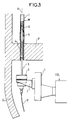
- FIG. 3 shows the elements of the terminal assembly 110.
- This assembly constitutes a part of the welding device installed in the tube to be repaired T, or receiving tube, which has been previously equipped with a welding sleeve M.
- This assembly is shown in position for welding. It is fixed to an elevator 1 which rises and falls, at the end of the arm of the carrier 112 and which is used to introduce and position the welding head in the sleeve. It includes a motorization cell 2, and the welding head.
- the latter is constituted by a flexible extension 3, a rigid extension 4, an optical cell 5 and a guide nose 6.
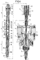
- Figure 4 shows a longitudinal section of this assembly.
- Cell 2 is fixed to the elevator 1 by a bracket 7 and includes a housing 8 and the base 9 of a turntable mounted in the axis of one another.
- This turntable has its fixed base and a rotating core 10 on which the flexible extension 3 is fixed by crimping.
- the housing 8 has a gas inlet channel 11 and a central bore 12.
- the optical fiber F is locked in a clamp 13 by the nut 14.
- This clamp slides axially in the bore 12 and is kept fixed in rotation by a key 15.
- the axial position of the clamp relative to the housing is adjustable using a ring 16, which makes it possible to adjust the position of the end of the fiber in relation to the welding head.
- the suitable welding altitude is obtained by adjustment with the elevator 1 of the position of the support bracket 7, and that the axial adjustment of the relative position of the optical fiber relative to the housing is obtained by rotation of the ring 16.
- This ring is mounted for free rotation in the housing by a bearing 17. In the figure, it is shown in manual version without servo-control. One can however easily realize its motorization (see figure 7). The sealing of the ring assembly is ensured by a seal 18.
- the flexible extension 3 is composed of a flexible outer sheath section 19 fitted at one end onto the core 10 of the turntable and comprising at the other end a rigid end piece 20 terminated by a thread 20A for screwing into the rigid extension 4.
- a sliding bearing 21 is mounted slidingly, the outside diameter of which is very slightly less than the diameter of the sleeve M in the case shown of the sleeving of the central tubes or of the receiving tube in the case of the sleeving of the peripheral tubes. This bearing guides the welding head in rotation.
- the end piece has an internal bore 22 through which the optical fiber passes.
- the rigid extender 4 is constituted by a cylindrical part 23 comprising at one end a thread which cooperates with the thread 20A of the flexible extender, and, at the other end a thread 24 for fixing the optical cell 5.
- This part has a bore internal 25 in which slides a bearing 26.
- This bearing is integral with the optical fiber F. It is constituted by two ball bearings and a ring. This bearing provides axial guidance for the movement of the optical fiber relative to the extender, and rotational guidance for the entire welding head compared to optical fiber.
- the end of the optical fiber is crimped into a ferrule 27 and a stop 27A, which hold the bearings of the bearing 26.
- the optical cell 5 is constituted by a tube portion 28, the two ends of which are tapped at 24 and 29.
- the lower thread 24 receives the rigid extension
- the upper thread 29 receives the warhead.
- a stack 30 of lenses L1, L2 and L3, spacers 32 and an optical part 33 is mounted inside this tube, fixed by two nuts 34.
- the lenses and the nuts have four generators distributed at 90 degrees of the grooves 35 intended for the passage of the purge gas from the weld zone.
- the optical part 33 consists of a cylinder, one of the faces of which is spherical 36 and the other of which is a plane mirror 37 inclined at 45 ° on the axis A.
- the light beam penetrates through the spherical face along the longitudinal axis and undergoes a radial reflection.
- the tube has an opening 38.
- the optical part has a groove 39 for the passage of the scanning gas.
- FIGS. 5A and 5B show two alternative embodiments of an optical cell.
- FIG. 5A represents an embodiment with two lenses L10 and L11, the second of which is offset to move the plane mirror R10 away from the focusing task.
- FIG. 5B represents a minimum configuration with two lenses L20 and L21 and a mirror R20. The preferred embodiment is however that of FIG. 4.
- the warhead is constituted by a tube 40 whose lower end is threaded for screwing on the optical cell. Inside this tube an axis 41 carries a centering brush 42 held by a nose 43. This axis slides in a bearing 44 force fitted into the tube 40; A projection 45 limits the axial movement of the axis in the tube.
- the welding head constituted by the outer sheath of the flexible extender, the cylindrical part 20, the rigid extender, the optical cell and the tube of the warhead performs, under the action of a non-rotating motor. shown included in the motor cell 2, a full 360 ° rotation guided by the centering brush 42 in the upper part and by the sliding bearing 21. These are the two support points on the internal surface of the sleeve M.
- the optical fiber remains fixed during this rotation, as well as the brush holder axis of the warhead. If two or more slightly offset beads are required, the welding head can be moved in the longitudinal axis by means of sliding bearings 21 and 43.
- the extensions and the welding head define a continuous annular space around the protective sheath 47 of the optical fiber. This space is interrupted by the ball bearings of the rigid extension and by the longitudinal grooves at the nuts and lenses. It allows the passage of the scanning gas from the housing 8 to the top of the weld.
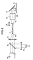
- FIG. 6 shows the principle of adjusting the focusing distance of the beam on the internal surface of the sleeve.
- the optical head is introduced into a tubular adjustment gauge MB having the same internal diameter as the sleeve to be welded.
- the adjustment laser 106 of the helium-neon type is then used, the visible light beam of which takes exactly the same path as the light from the welding laser.
- a separating plate 50 is installed at the exit of the laser 106, before a converging lens 51 which concentrates the light on the entry 105 of the fiber F.
- This plate lets pass the light beam coming from the laser, but reflects on a photovoltaic receiver 52 the beam from an illuminated task which is centered at point H on the internal surface S of the caliber MB and which constitutes a luminous object. If the axial position of the outlet end 49 of the optical fiber is varied along the arrow 56 relative to the optical cell, which comprises the lens assembly 30 and the mirror 37, the signal supplied by the photovoltaic receiver 52 is maximum for an optimal position of the optical fiber corresponding to a focusing of the light at the point of impact H.
- the optimum position is sought by action on the ring 16 and this position is stabilized by immobilization of this ring, taking into account the known offset between the position of the focal point of the HeNe beam and that of the focal point of the YAG beam.
- FIG. 7 shows a modified welding device in which the optimal axial position of the optical fiber is obtained by automatic adjustment of the position of a ring 216.
- This ring plays the same role as the ring 16, and it is driven by a adjustment motor 200 which is controlled by an acquisition and management central unit 202 after acquisition of data corresponding to a sleeve to be welded, the rest of the device being unchanged.
- Such a modification is compatible with the aims of the invention because the presetting of the position of the optical fiber described above for obtaining a minimum focal spot on the wall allows acceptable welding within a range of variation of the diameter.
- the adjustment operation comprises two phases: a data acquisition phase during which the central unit 202 controls the rotation motor, and an adjustment phase during which this same central unit controls the adjustment motor 200.
- the data acquisition is obtained by recording the curve of the signal received on the photovoltaic receiver 51 during a revolution of the welding head, with the beam emitted by the laser 106.
- the input of the fiber F is moved away from the lens 51 and coupled to the power laser 104.
- a laser control station 102 comprising the YAG laser 104 and the visible laser 106, a control station 108 of a carrier 112 installed inside the box is installed outside the reactor building of a nuclear power station. water from a steam generator G having leaking tubes such as T. In these tubes, sleeves such as M to be welded were accosted by a known method.
- the carrier carries the terminal assembly 110 of the device comprising the welding head which is connected connected to the laser control station by a flexible tube containing the optical fiber F and signal transmission cables 124.
- This assembly is introduced remotely terminal with the welding head in the sleeve to be welded, this head is placed in the high position, near the upper end of the sleeve using an elevator 1, a visible laser beam is sent into the optical cell 30, 37 and the distance curve from axis A to the surface to be welded is recorded on one revolution.
- the position of the optical fiber is then adjusted to obtain a minimum focal spot on the average diameter determined by the recorded distance curve, the welding laser beam is sent and the sleeve is welded on a revolution on the tube.
- place the welding head with the elevator in the low position, near the lower end of the sleeve send a visible laser beam into the optical cell and record the distance curve from the axis to the surface to be welded on a revolution.
- the position of the optical fiber is then adjusted to obtain a minimum focal spot on the average diameter determined by the recorded distance curve, the welding laser beam is sent and the sleeve is welded on a revolution.
Landscapes
- Physics & Mathematics (AREA)
- Optics & Photonics (AREA)
- Engineering & Computer Science (AREA)
- Plasma & Fusion (AREA)
- Mechanical Engineering (AREA)
- Laser Beam Processing (AREA)
- Monitoring And Testing Of Nuclear Reactors (AREA)
- Butt Welding And Welding Of Specific Article (AREA)
- Optical Couplings Of Light Guides (AREA)
Claims (6)
- Verfahren zum Einschweißen einer Muffe in ein Rohr aus der Entfernung, insbesondere in einem Dampferzeuger eines Kernkraftwerks, um eine Verbindung zwischen einem Aufnahmerohr (T), das eine Achse A aufweist, einerseits und einer einzuschweißenden Muffe (M), die eine Wand (S) aufweist und zuvor in diesen Rohr in Stellung gebracht wurde, andererseits herzustellen,
bestehend aus:- einem Arbeitsvorgang zum Instellungbringen eines Schweißkopfs (4, 5, 6) mit einer optischen Zelle in dem genannten Aufnahmerohr, wobei die optische Zelle ihrerseits aufweist:dadurch gekennzeichnet, daß die genannte Drehung der optischen Reflektiermittel (37) von einem Antriebselement (2) verursacht wird, das sich außerhalb des genannten Aufnahmerohrs (T) gegenüber dessen Eingang befindet und das mechanisch durch eine rohrförmige Verlängerungseinheit (19, 20, 23) mit den genannten optischen Reflektiermitteln verbunden ist, wobei diese Einheit in diesem Rohr um die genannte Lichtleitfaser (F) herum und dergestalt angeordnet ist, daß sie diese Faser nicht in Drehbewegung versetzt.- optische Reflektiermittel (37), die geeignet sind, ein Schweiß-Lichtbündel auf der genannten Achse (A) des Aufnahmerohrs zu empfangen und dieses Bündel auf die Wand der genannten zu schweißenden Muffe zu reflektieren,- und Fokussierungsmittel (30), die geeignet sind, dieses Bündel auf einen Auftreffpunkt (H) an der Wand der genannten zu schweißenden Muffe zu fokussieren, so daß an diesem Punkt eine Schweiße dieser Muffe an das genannte Aufnahmerohr ausgeführt wird,- wobei dieses Verfahren des weiteren aus einem Arbeitsvorgang zur Erzeugung eines genannten, zur Ausführung der genannten Schweiße geeigneten Schweißlichtbündels durch einen Schweißlaser (104) besteht, wobei sich dieser Laser in einem Bereich der Erzeugung des Lichtbündels (102) in Entfernung von dem genannten Aufnahmerohr befindet,- einem Arbeitsvorgang zum Instellungbringen einer Lichtleitfaser (F), um das genannte Schweißlichtbündel zu empfangen und es zu der genannten optischen Zelle zu leiten,- und einem Arbeitsvorgang zum Drehen des Auftreffpunkts, der durch eine Drehung von wenigstens den genannten optischen Reflektiermitteln (37) der genannten optischen Zelle (30, 37) um genannte Achse (A) des Aufnahmerohrs ausgeführt wird, um den genannten Auftreffpunkt (H) wenigstens einen Bogen auf der genannten zu schweißenden Muffe (M) beschreiben zu lassen, dergestalt daß eine Schweißnaht ausgeführt wird, - Verfahren nach Anspruch 1,
dadurch gekennzeichnet, daß die genannte Verlängerungseinheit (19, 20, 23) einen Schlauchmantel (19) aufweist, wobei diese Einheit und/oder die genannte optische Zelle (30, 37) durch ein externes Zentriermittel (21, 42) geführt wird, das wenigstens zu einer örtlich veränderbaren Anlage an der Wand (S) der genannten zu schweißenden Muffe (M) und/oder an der genannten Innenfläche des Aufnahmerohrs (T) kommt, wobei genannte Lichtleitfaser (F) durch ein internes Zentriermittel (26) geführt wird, das wenigstens zu einer örtlich veränderbaren Anlage an der genannten Verlängerungseinheit kommt. - Verfahren nach Anspruch 2,
dadurch gekennzeichnet, daß die genannte Lichtleitfaser (F) durch genanntes internes Zentriermittel (26) so geführt wird, daß nicht nur eine Drehung, sondern auch ein axiales Verschieben dieser Faser in der genannten Verlängerungseinheit (19, 20, 23) möglich ist, wobei diese Einheit die genannte optische Zelle (30, 37) axial führt. - Verfahren nach Anspruch 1, bei dem der genannte Schweißkopf (4, 5, 6) mit einem elastischen, externen Zentriermittel (42) versehen ist, um mit seinem gesamten Umfang an der Wand (S) der genannten zu schweißenden Muffe (M) in Anlage zu kommen, dadurch gekennzeichnet, daß das genannte Zentriermittel zu diesem Kopf frei drehbar montiert ist, um die Drehung dieses letzteren ohne Drehung dieses Zentriermittels möglich zu machen.
- Vorrichtung zum Einschweißen einer Muffe in ein Rohr aus der Entfernung, insbesondere in einem Dampferzeuger eines Kernkraftwerks, um eine Verbindung zwischen einem Aufnahmerohr (T), das eine Achse A aufweist, einerseits und einer einzuschweißenden Muffe (M), die eine Wand (S) aufweist und zuvor in diesen Rohr in Stellung gebracht wurde, andererseits herzustellen,
bestehend aus:- einem Schweißlaser (104) zur Erzeugung eines Schweißlichtbündels, das geeignet ist, eine Schweiße der genannten in genanntem Aufnahmerohr einzuschweißenden Muffe (M) auszuführen,- einem Schweißkopf (4, 5, 6), der geeignet ist, in genanntem Aufnahmerohr in Stellung gebracht zu werden, und mit einer optischen Zelle ausgestattet ist, die ihrerseits aufweist:dadurch gekennzeichnet, daß sie des weiteren besteht aus:- optische Reflektiermittel (37), zum Empfangen eines Schweiß-Lichtbündels auf der genannten Achse (A) des Aufnahmerohrs und zum Reflektieren dieses Bündels auf die Wand der genannten zu schweißenden Muffe,- und Fokussierungsmittel (30), zum Fokussieren dieses Bündels auf einen Auftreffpunkt (H) an der Wand der genannten einzuschweißenden Muffe, so daß an diesem Punkt eine Schweiße dieser Muffe an das genannte Aufnahmerohr ausgeführt wird,- wobei diese Vorrichtung des weiteren besteht aus:- einer elastischen Lichtfaser, die eine Leitfaser (F) bildet mit einerseits einem Eingang (105) zum Empfangen des genannten Schweiß-Lichtbündels, das von genanntem Schweißlaser (104) erzeugt wird, und andererseits einem Ausgang (49),- und internen Zentriermitteln (26), um diesen Ausgang relativ zur genannten optischen Zelle (30, 37) dergestalt zu halten, daß dieser Ausgang auf der genannten Achse (A) des Aufnahmerohrs (T) angeordnet ist, wenn der genannte Schweißkopf (4, 5, 6) in dieses Rohr eingeführt wird,- einem Antriebselement (2), das außerhalb des genannten Aufnahmerohrs (T) bleibt,- einer Verlängerungseinheit (19, 20, 23), die dieses Antriebelement mit der genannten optischen Zelle (30, 37) verbindet, um diese Zelle in eine Drehbewegung um genannte Achse (A) des Aufnahmerohrs herum zu versetzen, so daß der genannte Auftreffpunkt (H) wenigstens einen Bogen beschreibt, um eine Schweißnaht auszuführen, wobei diese Verlängerungseinheit die genannte Lichtleitfaser (F) umgibt,- den genannten internen Zentriermitteln (26), die in dieser Verlängerungseinheit in Anlage kommen und eine Drehbewegung dieser Einheit relativ zu dieser Faser dergestalt möglich machen, daß diese Faser nicht in Drehbewegung versetzt wird. - Vorrichtung nach Anspruch 5,
dadurch gekennzeichnet, daß der genannte Schweißkopf (4, 5, 6) mit einem elastischen, externen Zentriermittel (42) versehen ist, das relativ zu diesem Kopf frei um die genannte Achse (A) des Aufnahmerohrs drehbar montiert ist, um in Reibungsanlage an der genannten Wand (S) der genannten zu schweißenden Muffe zu kommen und bei der genannten Drehbewegung der genannten optischen Zelle (30, 37) bewegungslos zu bleiben.
Applications Claiming Priority (2)
| Application Number | Priority Date | Filing Date | Title |
|---|---|---|---|
| FR8813602A FR2637829A1 (fr) | 1988-10-14 | 1988-10-14 | Procede de dispositif de soudage a distance d'un manchon dans un tube notamment dans un generateur de vapeur de centrale nucleaire |
| FR8813602 | 1988-10-14 |
Publications (2)
| Publication Number | Publication Date |
|---|---|
| EP0367648A1 EP0367648A1 (de) | 1990-05-09 |
| EP0367648B1 true EP0367648B1 (de) | 1992-12-23 |
Family
ID=9371062
Family Applications (2)
| Application Number | Title | Priority Date | Filing Date |
|---|---|---|---|
| EP89402840A Expired - Lifetime EP0367648B1 (de) | 1988-10-14 | 1989-10-13 | Schweissverfahren und Schweissvorrichtung, um aus der Entfernung eine Muffe in ein Rohr, insbesondere innerhalb eines Dampferzeugers eines Kernkraftwerkes, einzuschweissen |
| EP89402841A Expired - Lifetime EP0364366B1 (de) | 1988-10-14 | 1989-10-13 | Verfahren und Vorrichtung zum Schweissen innerhalb eines Rohres, insbesondere eines Dampfgenerators eines Atomkraftwerkes, aus der Entfernung |
Family Applications After (1)
| Application Number | Title | Priority Date | Filing Date |
|---|---|---|---|
| EP89402841A Expired - Lifetime EP0364366B1 (de) | 1988-10-14 | 1989-10-13 | Verfahren und Vorrichtung zum Schweissen innerhalb eines Rohres, insbesondere eines Dampfgenerators eines Atomkraftwerkes, aus der Entfernung |
Country Status (9)
| Country | Link |
|---|---|
| US (2) | US4983796A (de) |
| EP (2) | EP0367648B1 (de) |
| JP (2) | JPH02151382A (de) |
| KR (2) | KR900006065A (de) |
| CN (2) | CN1028620C (de) |
| DE (2) | DE68903923T2 (de) |
| ES (2) | ES2037982T3 (de) |
| FR (1) | FR2637829A1 (de) |
| ZA (2) | ZA897778B (de) |
Families Citing this family (49)
| Publication number | Priority date | Publication date | Assignee | Title |
|---|---|---|---|---|
| FR2649923B1 (fr) * | 1989-06-28 | 1992-04-24 | Framatome Sa | Outillage de travail a l'interieur d'un element tubulaire |
| JP2659809B2 (ja) * | 1989-08-07 | 1997-09-30 | 三菱重工業株式会社 | レーザ用反射ミラー |
| FR2656557B1 (fr) * | 1989-12-28 | 1992-05-07 | Framatome Sa | Tete de travail au laser a l'interieur d'un tube. |
| FR2656558B1 (fr) * | 1989-12-28 | 1992-05-07 | Framatome Sa | Procede de travail au laser dans un tube. |
| FR2656818B1 (fr) * | 1989-12-28 | 1994-12-09 | Framatome Sa | Tete de travail au laser dans un tube. |
| US5066846A (en) * | 1990-06-26 | 1991-11-19 | Westinghouse Electric Corp. | System and method for laser welding the inner surface of heat exchanger tubes |
| JP2592173B2 (ja) * | 1990-07-09 | 1997-03-19 | 日本原子力発電株式会社 | 配管内の点検補修用ロボット |
| US5196671A (en) * | 1990-08-17 | 1993-03-23 | Siemens Aktiengesellschaft | Device and process for the laser welding of a tube |
| DE4115562A1 (de) * | 1990-08-17 | 1992-02-20 | Siemens Ag | Vorrichtung und verfahren zum laserschweissen eines rohres |
| FR2667528B1 (fr) * | 1990-10-08 | 1995-02-17 | Framatome Sa | Procede et appareil de travail au laser, notamment dans un tube. |
| FR2667810B1 (fr) * | 1990-10-10 | 1995-02-17 | Framatome Sa | Procede et dispositif de travail au laser avec controle a distance. |
| JPH04186696A (ja) * | 1990-11-16 | 1992-07-03 | Mitsubishi Electric Corp | ボンディング装置 |
| US5142118A (en) * | 1991-05-14 | 1992-08-25 | Progressive Tool & Industries Co. | Laser welding unit |
| FR2676675B1 (fr) * | 1991-05-15 | 1995-06-30 | Framatome Sa | Canne de soudage a faisceau laser, son utilisation pour le manchonnage de tubes et procede de surveillance de l'integrite d'une fibre optique de cette canne. |
| US5182429A (en) * | 1991-05-23 | 1993-01-26 | Westinghouse Electric Corp. | System and method for laser welding the inner surface of a tube |
| FR2679808A1 (fr) * | 1991-07-30 | 1993-02-05 | Framatome Sa | Tete de soudage au laser et son utilisation pour le manchonnage de tubes. |
| JP3214074B2 (ja) * | 1992-07-15 | 2001-10-02 | 石川島播磨重工業株式会社 | レーザ照射用トーチ |
| FR2698182B1 (fr) * | 1992-11-13 | 1994-12-16 | Commissariat Energie Atomique | Dispositif de contrôle du centrage d'un faisceau lumineux, application à l'introduction de ce faisceau dans une fibre optique. |
| US5789720A (en) * | 1992-12-30 | 1998-08-04 | Westinghouse Electric Corporation | Method of repairing a discontinuity on a tube by welding |
| US5359172A (en) * | 1992-12-30 | 1994-10-25 | Westinghouse Electric Corporation | Direct tube repair by laser welding |
| US5514849A (en) * | 1993-02-17 | 1996-05-07 | Electric Power Research Institute, Inc. | Rotating apparatus for repairing damaged tubes |
| US5430270A (en) * | 1993-02-17 | 1995-07-04 | Electric Power Research Institute, Inc. | Method and apparatus for repairing damaged tubes |
| US5491317A (en) * | 1993-09-13 | 1996-02-13 | Westinghouse Electric Corporation | System and method for laser welding an inner surface of a tubular member |
| US5371767A (en) * | 1994-02-01 | 1994-12-06 | Westinghouse Electric Corporation | System and method for laser welding an inner surface of a small diameter tubular member |
| US5591358A (en) * | 1994-03-23 | 1997-01-07 | Progressive Tool & Industries Co. | Apparatus for clamping and laser welding |
| US5611948A (en) * | 1994-10-31 | 1997-03-18 | Westinghouse Electric Corporation | Apparatus and method for remotely positioning a probe in a tubular member |
| US5667706A (en) * | 1996-05-03 | 1997-09-16 | Westinghouse Electric Corporation | Apparatus and method for laser welding the inner surface of a tube |
| FR2761625B1 (fr) * | 1997-04-07 | 1999-08-20 | Soc D Mecanique D Irigny | Procede et dispositif pour le soudage d'appendices sur un tube de verin |
| DE19741028C1 (de) * | 1997-09-18 | 1998-11-05 | Rheinmetall Ind Ag | Vorrichtung zum Härten der Innenkontur eines Waffenrohres mit Laserstrahlung |
| US6043294A (en) * | 1998-01-29 | 2000-03-28 | Gate Technologies International, Inc. | Method of and apparatus for optically enhancing chemical reactions |
| SE9801590L (sv) * | 1998-05-07 | 2000-01-21 | Permanova Lasersystem Ab | Anordning för att bestämma fokalpunktens läge i ett laserbearbetningssystem |
| JP2000046987A (ja) * | 1998-07-27 | 2000-02-18 | Toshiba Corp | 原子炉の炉心内配管部保全装置 |
| US7150328B2 (en) * | 2000-10-13 | 2006-12-19 | Shell Oil Company | Method for interconnecting adjacent expandable pipes |
| DE50306181D1 (de) * | 2003-04-01 | 2007-02-15 | Gehring Gmbh Maschf | Werkzeug zur Feinbearbeitung mit Laserstrahl der Oberfläche einer Bohrung |
| DE10332909B4 (de) * | 2003-07-19 | 2007-12-27 | Stabilus Gmbh | Verstellelement |
| US20070297556A1 (en) * | 2006-05-24 | 2007-12-27 | Keith Spencer | Full function precision welding system |
| DE102010032958A1 (de) * | 2010-07-30 | 2012-02-02 | Messer Cutting & Welding Gmbh | Verfahren und Vorrichtung zum thermischen Bearbeiten eines Werkstücks mittels Laserstrahl |
| WO2012050085A1 (ja) * | 2010-10-14 | 2012-04-19 | Matsumoto Terumasa | 冷凍サイクルの熱交換器及びその製造方法 |
| CN102179650A (zh) * | 2011-05-25 | 2011-09-14 | 烟台力凯电子科技有限公司 | 一种点焊包装一体机焊头调节装置 |
| DE102011121204A1 (de) * | 2011-12-16 | 2013-06-20 | Westinghouse Electric Germany Gmbh | Dampferzeugerheizrohrreparaturmittel und Reparaturverfahren |
| CN104551385B (zh) * | 2015-01-30 | 2017-03-29 | 大族激光科技产业集团股份有限公司 | 光纤激光加工头 |
| CN106154441B (zh) * | 2016-08-29 | 2018-03-30 | 成都全码特时代科技有限公司 | 一种能用于改善通用接口的旁射式光纤刀头 |
| CN106168695B (zh) * | 2016-08-29 | 2018-05-08 | 成都全码特时代科技有限公司 | 一种自动控制打开和关闭状态的光纤夹具装置 |
| IT201700018859A1 (it) * | 2017-02-20 | 2018-08-20 | Innovative Welding Solutions Bv | Dispositivo e metodo per unire tubolari metallici di pozzi di perforazione |
| EP3825057B1 (de) * | 2017-02-20 | 2023-05-03 | Innovative Welding Solutions B.V. | Vorrichtung und verfahren zur verbindung von metallischen rohren von bohrlöchern |
| CN108857065A (zh) * | 2018-09-12 | 2018-11-23 | 上海电气核电设备有限公司 | 一种核电蒸汽发生器的焊接方法 |
| FR3123582A1 (fr) * | 2021-06-04 | 2022-12-09 | Serimax Holdings | Dispositif de soudage de tube, ligne de production le comprenant, et procédé de soudage de tubes associé |
| CN114147362A (zh) * | 2021-12-08 | 2022-03-08 | 西北有色金属研究院 | 提高空间核反应堆容器不锈钢管板接头焊缝耐蚀性能的方法 |
| CN119635041B (zh) * | 2024-11-11 | 2025-10-03 | 江西洪都航空工业集团有限责任公司 | 一种智能薄壁导管柔性焊接设备 |
Family Cites Families (6)
| Publication number | Priority date | Publication date | Assignee | Title |
|---|---|---|---|---|
| US4654136A (en) * | 1984-12-17 | 1987-03-31 | The Dow Chemical Company | Monopolar or bipolar electrochemical terminal unit having a novel electric current transmission element |
| FR2588380B1 (fr) * | 1985-10-07 | 1988-05-27 | Commissariat Energie Atomique | Dispositif d'examen a distance de defauts debouchant a la surface interne d'une cavite profonde |
| US4694136A (en) * | 1986-01-23 | 1987-09-15 | Westinghouse Electric Corp. | Laser welding of a sleeve within a tube |
| DE3778189D1 (de) * | 1986-01-23 | 1992-05-21 | Westinghouse Electric Corp | Laserschweisskopf zum verschweissen einer muffe mit einem rohr. |
| FR2598209B1 (fr) * | 1986-04-30 | 1988-08-12 | Framatome Sa | Procede et dispositif de chemisage a distance d'un tube de generateur de vapeur d'un reacteur nucleaire a eau sous pression. |
| US4827098A (en) * | 1987-07-06 | 1989-05-02 | Westinghouse Electric Corp. | Flexible laser welding head for sleeve-to-tube welding |
-
1988
- 1988-10-14 FR FR8813602A patent/FR2637829A1/fr active Pending
-
1989
- 1989-10-13 JP JP1267970A patent/JPH02151382A/ja active Pending
- 1989-10-13 JP JP1267971A patent/JPH02151383A/ja active Pending
- 1989-10-13 ES ES198989402840T patent/ES2037982T3/es not_active Expired - Lifetime
- 1989-10-13 DE DE8989402841T patent/DE68903923T2/de not_active Expired - Fee Related
- 1989-10-13 EP EP89402840A patent/EP0367648B1/de not_active Expired - Lifetime
- 1989-10-13 EP EP89402841A patent/EP0364366B1/de not_active Expired - Lifetime
- 1989-10-13 DE DE8989402840T patent/DE68904049T2/de not_active Expired - Fee Related
- 1989-10-13 ES ES198989402841T patent/ES2037449T3/es not_active Expired - Lifetime
- 1989-10-13 ZA ZA897778A patent/ZA897778B/xx unknown
- 1989-10-13 ZA ZA897777A patent/ZA897777B/xx unknown
- 1989-10-14 CN CN89108588A patent/CN1028620C/zh not_active Expired - Fee Related
- 1989-10-14 KR KR1019890014807A patent/KR900006065A/ko not_active Withdrawn
- 1989-10-14 KR KR1019890014808A patent/KR900006066A/ko not_active Withdrawn
- 1989-10-14 CN CN89107927A patent/CN1018248B/zh not_active Expired
- 1989-10-16 US US07/422,171 patent/US4983796A/en not_active Expired - Fee Related
- 1989-10-16 US US07/422,363 patent/US4978834A/en not_active Expired - Fee Related
Non-Patent Citations (3)
| Title |
|---|
| PATENT ABSTRACTS OF JAPAN vol. 5, no. 143 (M-87)(815), 9 September 1981 ; & JP-A-56 74393 (TOKYO SHIBAURA DENKI K.K.) * |
| PATENT ABSTRACTS OF JAPAN, vol. 4, no. 164 (M-41)(646), 14 November 1980 ; & JP-A-55 114490 (TOKYO SHIBAURA DENKI K.K.) * |
| THE BELL SYSTEM TECHNICAL JOURNAL vol. 62, no. 8, part 1, Octobre 1983, pages 2479-2492 ; C. LIN et al. : "High-Power Lasers and Optical Waveguides for robotic Material-Processing Application" * |
Also Published As
| Publication number | Publication date |
|---|---|
| CN1041718A (zh) | 1990-05-02 |
| DE68903923D1 (de) | 1993-01-28 |
| JPH02151382A (ja) | 1990-06-11 |
| EP0364366A3 (en) | 1990-09-12 |
| EP0364366B1 (de) | 1992-12-16 |
| CN1043103A (zh) | 1990-06-20 |
| ZA897777B (en) | 1990-07-25 |
| EP0364366A2 (de) | 1990-04-18 |
| US4978834A (en) | 1990-12-18 |
| FR2637829A1 (fr) | 1990-04-20 |
| DE68903923T2 (de) | 1993-06-09 |
| ZA897778B (en) | 1990-07-25 |
| US4983796A (en) | 1991-01-08 |
| EP0367648A1 (de) | 1990-05-09 |
| ES2037449T3 (es) | 1993-06-16 |
| ES2037982T3 (es) | 1993-07-01 |
| DE68904049T2 (de) | 1993-04-29 |
| CN1018248B (zh) | 1992-09-16 |
| JPH02151383A (ja) | 1990-06-11 |
| CN1028620C (zh) | 1995-05-31 |
| KR900006065A (ko) | 1990-05-07 |
| KR900006066A (ko) | 1990-05-07 |
| DE68904049D1 (de) | 1993-02-04 |
Similar Documents
| Publication | Publication Date | Title |
|---|---|---|
| EP0367648B1 (de) | Schweissverfahren und Schweissvorrichtung, um aus der Entfernung eine Muffe in ein Rohr, insbesondere innerhalb eines Dampferzeugers eines Kernkraftwerkes, einzuschweissen | |
| EP0408405B1 (de) | Vorrichtung zum Laserschweissen im Inneren eines Rohrelementes | |
| EP0597771B1 (de) | Überwachungseinrichtung zur optischer Bündelzentrierung, Verwendung zur Bündeleinführung in optische Faser | |
| FR2698576A1 (fr) | Procédé et dispositif de réparation d'une zone défectueuse de la paroi d'une pièce métallique et en particulier d'une pièce tubulaire. | |
| EP0354090A2 (de) | Zerstörungsfreie Ultraschallvorrichtung für eine kreisförmige Schweissstelle im Inneren eines Rohres eines Dampferzeugers | |
| EP0480793B1 (de) | Vorrichtung und Installation zum Laserschweissen von Brennstäben oder dergleichen | |
| JP2014529056A (ja) | 核燃料棒のレーザー溶接方法 | |
| FR2526532A1 (fr) | Appareil pour le controle des tubes d'un echangeur de chaleur a une distance donnee de l'extremite de ces tubes | |
| FR2649923A1 (fr) | Outillage de travail a l'interieur d'un element tubulaire | |
| EP0418170B1 (de) | Gerät und Verfahren zum Schweissen von Werkstücken mittels eines Laserstrahls | |
| EP1567301B1 (de) | Vorrichtung und verfahren zum bewegen des fokuspunktes eines hochenergiestrahles | |
| EP0779525A1 (de) | Vorrichtung für die Einkopplung eines Leistungslaserstrahls in eine optische Faser | |
| EP1264316B1 (de) | Schwei$verfahren zum dichten verschlie$en einer einfüllöffnung eines kernbrennstab-verschlussstücks | |
| EP0480792A1 (de) | Vorrichtung zum Laserbohren und/oder Verschliessen des Loches am Brennstabrohr. | |
| EP0514235A1 (de) | Laserstrahlschweissstab, dessen Benutzung zum Rohrhübeneinbringen und Verfahren zur Überwachung der Integrität einer optischen Faser | |
| FR2677567A1 (fr) | Procede et dispositif de controle du fonctionnement d'une chaine optique, pour faisceau laser, portee par un outil de soudage. | |
| FR2722717A1 (fr) | Procede et ligne de reparation d'un defaut de fermeture d'un tube metallique contenant au moins une fibre optiue de transmission | |
| EP0583187A1 (de) | Überprüfungssystem für die Führungselemente eines Führungsrohrs in den oberen Einbauten eines Druckwasserkernreaktors | |
| EP0685291A1 (de) | Verfahren und Vorrichtung zum Laserstrahlschweissen eines schwer zugänglichen Elements | |
| FR2679025A1 (fr) | Procede et dispositif de controle d'une surface. | |
| EP0558403A1 (de) | Vorrichtung zum Nachprüfung der internen Oberfläche eines Rohrs, insbesondere in einem Dampferzeuger | |
| FR2732918A1 (fr) | Procede et dispositif d'introduction d'un outil en position centree a l'interieur d'une partie d'extremite d'un tube | |
| FR2692712A1 (fr) | Dispositif d'intervention à l'intérieur d'un tube de générateur de vapeur d'un réacteur nucléaire à eau sous pression. | |
| FR2667528A1 (fr) | Procede et appareil de travail au laser, notamment dans un tube. | |
| FR2720310A1 (fr) | Procédé et dispositif de travail au laser sur une surface métallique peu accessible. |
Legal Events
| Date | Code | Title | Description |
|---|---|---|---|
| PUAI | Public reference made under article 153(3) epc to a published international application that has entered the european phase |
Free format text: ORIGINAL CODE: 0009012 |
|
| AK | Designated contracting states |
Kind code of ref document: A1 Designated state(s): BE CH DE ES FR GB LI SE |
|
| 17P | Request for examination filed |
Effective date: 19901103 |
|
| 17Q | First examination report despatched |
Effective date: 19920403 |
|
| GRAA | (expected) grant |
Free format text: ORIGINAL CODE: 0009210 |
|
| AK | Designated contracting states |
Kind code of ref document: B1 Designated state(s): BE CH DE ES FR GB LI SE |
|
| GBT | Gb: translation of ep patent filed (gb section 77(6)(a)/1977) |
Effective date: 19921222 |
|
| REF | Corresponds to: |
Ref document number: 68904049 Country of ref document: DE Date of ref document: 19930204 |
|
| REG | Reference to a national code |
Ref country code: ES Ref legal event code: FG2A Ref document number: 2037982 Country of ref document: ES Kind code of ref document: T3 |
|
| PLBE | No opposition filed within time limit |
Free format text: ORIGINAL CODE: 0009261 |
|
| STAA | Information on the status of an ep patent application or granted ep patent |
Free format text: STATUS: NO OPPOSITION FILED WITHIN TIME LIMIT |
|
| 26N | No opposition filed | ||
| PGFP | Annual fee paid to national office [announced via postgrant information from national office to epo] |
Ref country code: GB Payment date: 19940823 Year of fee payment: 6 |
|
| PGFP | Annual fee paid to national office [announced via postgrant information from national office to epo] |
Ref country code: ES Payment date: 19940907 Year of fee payment: 6 |
|
| PGFP | Annual fee paid to national office [announced via postgrant information from national office to epo] |
Ref country code: CH Payment date: 19940921 Year of fee payment: 6 |
|
| PGFP | Annual fee paid to national office [announced via postgrant information from national office to epo] |
Ref country code: SE Payment date: 19940922 Year of fee payment: 6 |
|
| PGFP | Annual fee paid to national office [announced via postgrant information from national office to epo] |
Ref country code: FR Payment date: 19940929 Year of fee payment: 6 Ref country code: BE Payment date: 19940929 Year of fee payment: 6 |
|
| PGFP | Annual fee paid to national office [announced via postgrant information from national office to epo] |
Ref country code: DE Payment date: 19940930 Year of fee payment: 6 |
|
| EAL | Se: european patent in force in sweden |
Ref document number: 89402840.6 |
|
| PG25 | Lapsed in a contracting state [announced via postgrant information from national office to epo] |
Ref country code: GB Effective date: 19951013 |
|
| PG25 | Lapsed in a contracting state [announced via postgrant information from national office to epo] |
Ref country code: SE Effective date: 19951014 Ref country code: ES Free format text: LAPSE BECAUSE OF THE APPLICANT RENOUNCES Effective date: 19951014 |
|
| PG25 | Lapsed in a contracting state [announced via postgrant information from national office to epo] |
Ref country code: LI Effective date: 19951031 Ref country code: CH Effective date: 19951031 Ref country code: BE Effective date: 19951031 |
|
| BERE | Be: lapsed |
Owner name: FRAMATOME Effective date: 19951031 |
|
| GBPC | Gb: european patent ceased through non-payment of renewal fee |
Effective date: 19951013 |
|
| REG | Reference to a national code |
Ref country code: CH Ref legal event code: PL |
|
| PG25 | Lapsed in a contracting state [announced via postgrant information from national office to epo] |
Ref country code: FR Effective date: 19960628 |
|
| EUG | Se: european patent has lapsed |
Ref document number: 89402840.6 |
|
| PG25 | Lapsed in a contracting state [announced via postgrant information from national office to epo] |
Ref country code: DE Effective date: 19960702 |
|
| REG | Reference to a national code |
Ref country code: FR Ref legal event code: ST |
|
| REG | Reference to a national code |
Ref country code: ES Ref legal event code: FD2A Effective date: 19991007 |