EP0558403A1 - Vorrichtung zum Nachprüfung der internen Oberfläche eines Rohrs, insbesondere in einem Dampferzeuger - Google Patents
Vorrichtung zum Nachprüfung der internen Oberfläche eines Rohrs, insbesondere in einem Dampferzeuger Download PDFInfo
- Publication number
- EP0558403A1 EP0558403A1 EP93400465A EP93400465A EP0558403A1 EP 0558403 A1 EP0558403 A1 EP 0558403A1 EP 93400465 A EP93400465 A EP 93400465A EP 93400465 A EP93400465 A EP 93400465A EP 0558403 A1 EP0558403 A1 EP 0558403A1
- Authority
- EP
- European Patent Office
- Prior art keywords
- tube
- optical path
- internal surface
- source
- inspection head
- Prior art date
- Legal status (The legal status is an assumption and is not a legal conclusion. Google has not performed a legal analysis and makes no representation as to the accuracy of the status listed.)
- Withdrawn
Links
- 238000012544 monitoring process Methods 0.000 title 1
- 238000007689 inspection Methods 0.000 claims abstract description 30
- 230000003287 optical effect Effects 0.000 claims abstract description 28
- 238000004458 analytical method Methods 0.000 claims abstract description 14
- 238000013507 mapping Methods 0.000 claims abstract description 11
- 238000006073 displacement reaction Methods 0.000 claims abstract description 9
- 239000003638 chemical reducing agent Substances 0.000 claims description 4
- 238000012937 correction Methods 0.000 description 3
- 238000010586 diagram Methods 0.000 description 3
- 238000004556 laser interferometry Methods 0.000 description 2
- 238000012545 processing Methods 0.000 description 2
- 238000007796 conventional method Methods 0.000 description 1
- 230000007547 defect Effects 0.000 description 1
- 239000012530 fluid Substances 0.000 description 1
- 230000004886 head movement Effects 0.000 description 1
- 239000004579 marble Substances 0.000 description 1
- 230000001681 protective effect Effects 0.000 description 1
- 238000010408 sweeping Methods 0.000 description 1
- 238000013519 translation Methods 0.000 description 1
- 238000002604 ultrasonography Methods 0.000 description 1
- 230000004304 visual acuity Effects 0.000 description 1
- XLYOFNOQVPJJNP-UHFFFAOYSA-N water Substances O XLYOFNOQVPJJNP-UHFFFAOYSA-N 0.000 description 1
- 238000003466 welding Methods 0.000 description 1
Images




Classifications
-
- G—PHYSICS
- G01—MEASURING; TESTING
- G01N—INVESTIGATING OR ANALYSING MATERIALS BY DETERMINING THEIR CHEMICAL OR PHYSICAL PROPERTIES
- G01N21/00—Investigating or analysing materials by the use of optical means, i.e. using sub-millimetre waves, infrared, visible or ultraviolet light
- G01N21/84—Systems specially adapted for particular applications
- G01N21/88—Investigating the presence of flaws or contamination
- G01N21/95—Investigating the presence of flaws or contamination characterised by the material or shape of the object to be examined
- G01N21/954—Inspecting the inner surface of hollow bodies, e.g. bores
-
- G—PHYSICS
- G21—NUCLEAR PHYSICS; NUCLEAR ENGINEERING
- G21C—NUCLEAR REACTORS
- G21C17/00—Monitoring; Testing ; Maintaining
- G21C17/017—Inspection or maintenance of pipe-lines or tubes in nuclear installations
-
- Y—GENERAL TAGGING OF NEW TECHNOLOGICAL DEVELOPMENTS; GENERAL TAGGING OF CROSS-SECTIONAL TECHNOLOGIES SPANNING OVER SEVERAL SECTIONS OF THE IPC; TECHNICAL SUBJECTS COVERED BY FORMER USPC CROSS-REFERENCE ART COLLECTIONS [XRACs] AND DIGESTS
- Y02—TECHNOLOGIES OR APPLICATIONS FOR MITIGATION OR ADAPTATION AGAINST CLIMATE CHANGE
- Y02E—REDUCTION OF GREENHOUSE GAS [GHG] EMISSIONS, RELATED TO ENERGY GENERATION, TRANSMISSION OR DISTRIBUTION
- Y02E30/00—Energy generation of nuclear origin
- Y02E30/30—Nuclear fission reactors
Definitions
- the present invention relates to a device for controlling the internal surface of a tube, in particular a steam generator.
- These steam generators are for example used in pressurized water nuclear power plants.
- Such steam generators comprise a bundle of tubes, each having the general shape of a U, the ends of which are fixed to a so-called tubular plate and are connected respectively to the primary fluid inlets and outlets of the generator.
- This fixing of the ends of each tube on the tube plate is for example carried out by welding and swaging.
- endoscopes make it very difficult to examine the internal surface of a tube and micro-cameras require a large amount of external light as well as a homogeneous distribution of this light over the surface to be examined.
- the object of the invention is therefore to solve these problems by proposing a device for controlling the internal surface of a tube, in particular a steam generator, which is simple, reliable and whose resolving power is extremely high.
- the subject of the invention is a device for controlling the internal surface of a tube, in particular a steam generator, characterized in that it comprises a laser source provided with means for focusing the beam emitted by this source, adapted to emit a laser beam on an optical path in the direction of an inspection head, extending in the tube and the position of which in the latter is controlled by displacement means according to a helical movement, said inspection head comprising means for deflecting the beam emitted on the optical path, towards the internal surface of the tube to be inspected and the corresponding beam reflected by it, on the optical path, means for deflecting the reflected beam, arranged on the optical path, and adapted to deflect the at least part of the beam reflected towards means for analyzing this beam, connected to means for controlling means for focusing the beam emitted by the source on the optical path, in order to keep this beam focused on the internal surface of the tube and at means for mapping the internal surface of the tube, from the output information from these analysis means and from the position of the inspection head and in that
- the optical path comprises two portions approximately perpendicular to one another, one extending between the laser source and a fixed return pentaprism and the other between the pentaprism and the inspection head.
- This source comprises for example a laser diode of a type known per se and is associated with a diaphragm 2 with variable aperture, making it possible to avoid energy loss from this beam on the optical path.
- This laser source is also provided with means 3 for focusing the beam emitted by this source, adapted to emit a laser beam on an optical path in the direction of an inspection head designated by the general reference 4 in this figure.
- the optical path of the laser beam is generally designated by the reference 5 and will be described in more detail below, but it can already be seen with reference to this FIG. 1, that it comprises two portions, one 5a and the other 5b, extending approximately perpendicularly to each other.
- a fixed return pentaprism designated by the general reference 6 in this Fig. 1 is disposed between these two portions of the optical path to ensure optical continuity between these two portions of the path.
- Lenses 7 and 8 are also arranged on this optical path, one 7 in the first portion thereof and the other 8, in the second portion thereof, for example at the entrance of the head d 4 previously mentioned inspection.
- the laser beams emitted by the source and reflected by the tube T transit in the same optical path, in known manner.
- the deflection means 9 of the inspection head can be constituted by a mirror.
- means for deflecting at least part of the reflected beam are also arranged, for example in the first portion 5a of the optical path.
- These deflection means comprise for example a semi-transparent blade.
- the analysis means 12 are also connected to means 14 for mapping the internal surface of the tube from the information output from these analysis means and from the position of the inspection head 4 in the tube, delivered by example by means for determining the position of the head displacement means.
- mapping means are for example formed by a part of a computer.
- the photodetectors 19, 20 are associated respectively with fixed aperture diaphragms 21 and 22, making it possible to obtain a constant section of the light beam striking each of these photodetectors, the sections of these light beams being determined one relative to the other and according to the characteristics of these photodetectors and of the optical path, in a known manner.
- the photodetector 18 delivers an electrical signal directly proportional to the light energy it receives and which corresponds to an energy reflected by the portion of the internal surface inspected.
- this computer acts accordingly on the emission source of the laser beam and on the variable diaphragm 2 in order to adapt these to the inspection conditions encountered.
- the device which has just been described is a device which makes it possible to automatically focus a laser beam on the internal surface of a tube, by determining corrections to be made to the position of focusing means in function of the geometric variations encountered on the internal surface of this tube, these corrections making it possible, in association with information on the position of the inspection head in the tube, to carry out a mapping of this internal surface of the tube.
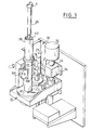
- the inspection head designated by the general reference 4 is fixed to the end of a support rod designated by the general reference 25 in these figures.
- This rod is hollow and its end opposite to that carrying the inspection head, is associated with the means 26 for moving this head according to a helical movement in the tube T.
- this end of the rod 25 is also disposed opposite the fixed return pentaprism 6 described above, so as to allow the propagation of the laser beam on the one hand between the laser source 1 and the return pentaprism 6 and on the other hand, between this pentaprism 6 and the inspection head 4 through the central recess of this rod 25, which then at least partially delimits the second portion 5b of the optical path described with regard to FIG. 1.
- the means for moving the head 4 advantageously comprise a first geared motor designated by the general reference 27 in these figures, for driving the rod 25 in rotation, for example by means of a toothed pinion 28 for output from this geared motor connected by means of a toothed belt 29 to a corresponding toothed pinion 30 for rotating the corresponding end of the rod.
- This rotational drive motor-reducer assembly pinions and toothed belt, is fixed on a support plate 31 whose height position is determined by a second motor-reducer 32 whose output shaft cooperates with a screw system - nut 33, 34 to move in translation this plate 31 and therefore the rod 25 and the inspection head 4, in the tube.
- These means can be formed for example by drive means with rollers 36, 37 and 38 arranged on either side of the rod, one of these rollers, for example the roller 36, being connected to a motor drive reducer not shown, while the others constitute guide rollers.
- rollers are in abutment against a sheath 39 disposed around the rod 25 and the function of which will be described in more detail below.
- An intermediate sleeve 40 is also interposed between this rod 25 and this sheath 39.
- this sleeve is adapted to move expandable means 41, provided at one end of the sheath, towards an active position for centering and holding the position of the head 4 in the tube T.
- the rod 25, the intermediate sleeve 40 and the sleeve 39 have bases respectively 42, 43 and 44.
- Elastic means 45 are interposed between the base 44 of the sleeve 39 and the base 42 of the rod 25 to urge these bases in the direction of one another.
- the means 35 for rapid displacement of this assembly constituted for example by the drive rollers 36 and the guide rollers of which only one 37 is shown in these figures, are supplied to cause rapid movement of this assembly inside the tube T.
- the ascent of the assembly continues as long as the base 44 of the sheath is not in abutment against the tube plate 47.
- the position of the head in the tube is determined by the position of the mounting plate.
- support 31 and the sheath 39 is also engaged in the tube T.
- the next phase shown in Fig.6, consists in moving the intermediate sleeve 40 from a retracted position to an active position, so as to cause the displacement of the expandable members 41 of the sleeve 39 from their retracted position to their active position to ensure good centering and good holding in position of the head 4 in the tube T.
- the geared motors 27 for rotating the rod and 32 for translational movement of the rod in the tube by raising the support plate 31 can be supplied to ensure corresponding displacements of the head in the tube and therefore a sweeping of the internal surface of the latter by this head, the elastic means 45 urging the base 42 of the rod 25 in the direction of the base 44 of the sleeve 39.
- FIG.8 a block diagram illustrating the operation of the mapping means forming part of the device according to the invention.
- the inspection head 4 makes it possible to deliver information, through control means for example outputs of this head, designated by the general reference 50 in this figure, to an acquisition module 51.
- This data acquisition is done under the control of a supervision module 52 also driving modules 53 for supplying the geared motors described above, through the control means 50.
- a module 54 makes it possible to store these various acquisitions before their processing in the module 52, possible display on a screen 55 and archiving in a module 56.
- the processing module designated by the general reference 52 makes it possible to carry out a mapping of the zone of the tube inspected by associating the information of focusing corrections applied on the focusing means 3 with for example the driving information of the geared motors, making it possible determine the position of the head in the tube.
- This different mapping information can be stored and viewed to determine the presence of micro-defects or micro-cracks on the internal surface of the tube and to locate these defects if necessary.
- This device can be used to control the areas of attachment of tubes to the tube plates, for example steam generators used in nuclear power plants or the like, but can also find applications in other fields.
Landscapes
- Physics & Mathematics (AREA)
- Engineering & Computer Science (AREA)
- General Health & Medical Sciences (AREA)
- Chemical & Material Sciences (AREA)
- Analytical Chemistry (AREA)
- Biochemistry (AREA)
- Life Sciences & Earth Sciences (AREA)
- General Physics & Mathematics (AREA)
- Immunology (AREA)
- Pathology (AREA)
- Health & Medical Sciences (AREA)
- Plasma & Fusion (AREA)
- General Engineering & Computer Science (AREA)
- High Energy & Nuclear Physics (AREA)
- Investigating Materials By The Use Of Optical Means Adapted For Particular Applications (AREA)
Applications Claiming Priority (2)
| Application Number | Priority Date | Filing Date | Title |
|---|---|---|---|
| FR9202402A FR2688063B1 (fr) | 1992-02-28 | 1992-02-28 | Dispositif de controle de la surface interne d'un tube notamment d'un generateur de vapeur. |
| FR9202402 | 1992-02-28 |
Publications (1)
| Publication Number | Publication Date |
|---|---|
| EP0558403A1 true EP0558403A1 (de) | 1993-09-01 |
Family
ID=9427196
Family Applications (1)
| Application Number | Title | Priority Date | Filing Date |
|---|---|---|---|
| EP93400465A Withdrawn EP0558403A1 (de) | 1992-02-28 | 1993-02-23 | Vorrichtung zum Nachprüfung der internen Oberfläche eines Rohrs, insbesondere in einem Dampferzeuger |
Country Status (2)
| Country | Link |
|---|---|
| EP (1) | EP0558403A1 (de) |
| FR (1) | FR2688063B1 (de) |
Cited By (2)
| Publication number | Priority date | Publication date | Assignee | Title |
|---|---|---|---|---|
| CN113607050A (zh) * | 2021-07-14 | 2021-11-05 | 中国大恒(集团)有限公司北京图像视觉技术分公司 | 一种相机测试工装 |
| CN114965728A (zh) * | 2021-02-18 | 2022-08-30 | 塞莫费雪科学(不来梅)有限公司 | 用数据非依赖性采集质谱分析生物分子样品的方法和设备 |
Citations (7)
| Publication number | Priority date | Publication date | Assignee | Title |
|---|---|---|---|---|
| US4055382A (en) * | 1975-01-29 | 1977-10-25 | Skf Industrial Trading And Development Company, B.V. | Testing method for the separate determination of varying work surface flaws and arrangement for said method |
| GB2047882A (en) * | 1979-02-27 | 1980-12-03 | Diffracto Ltd | Determinationa of physical characteristics of surfaces |
| GB2076964A (en) * | 1980-05-28 | 1981-12-09 | Fiat Auto Spa | Inspecting workpiece surface by diffraction patterns |
| GB2100424A (en) * | 1981-06-11 | 1982-12-22 | Vektronics Inc | Methods and apparatus for scanning an object |
| EP0222635A1 (de) * | 1985-10-07 | 1987-05-20 | Commissariat A L'energie Atomique | Fernbediente Kontrollvorrichtung von Fehlern auf der Innenfläche eines tiefen Hohlkörpers |
| EP0232771A2 (de) * | 1986-02-05 | 1987-08-19 | Erwin Sick GmbH Optik-Elektronik | Optische Abtastvorrichtung |
| EP0267705A2 (de) * | 1986-11-10 | 1988-05-18 | Sira Limited | Apparat zur Oberflächenüberprüfung oder -abstandsmessung |
Family Cites Families (4)
| Publication number | Priority date | Publication date | Assignee | Title |
|---|---|---|---|---|
| JPS5582952A (en) * | 1978-12-19 | 1980-06-23 | Osawa Shokai:Kk | Inspection system of inner surface of small tube |
| JPS55117946A (en) * | 1979-03-06 | 1980-09-10 | Sumitomo Metal Ind Ltd | Flaw detection method of hollow shaft inside surface |
| JPS55144532A (en) * | 1979-04-27 | 1980-11-11 | Kawasaki Steel Corp | Method and device for sounding in cylindrical tube |
| JPH1193631A (ja) * | 1997-09-16 | 1999-04-06 | Fuji Robin Ind Ltd | 手動始動式4サイクルエンジン用デコンプ装置 |
-
1992
- 1992-02-28 FR FR9202402A patent/FR2688063B1/fr not_active Expired - Fee Related
-
1993
- 1993-02-23 EP EP93400465A patent/EP0558403A1/de not_active Withdrawn
Patent Citations (7)
| Publication number | Priority date | Publication date | Assignee | Title |
|---|---|---|---|---|
| US4055382A (en) * | 1975-01-29 | 1977-10-25 | Skf Industrial Trading And Development Company, B.V. | Testing method for the separate determination of varying work surface flaws and arrangement for said method |
| GB2047882A (en) * | 1979-02-27 | 1980-12-03 | Diffracto Ltd | Determinationa of physical characteristics of surfaces |
| GB2076964A (en) * | 1980-05-28 | 1981-12-09 | Fiat Auto Spa | Inspecting workpiece surface by diffraction patterns |
| GB2100424A (en) * | 1981-06-11 | 1982-12-22 | Vektronics Inc | Methods and apparatus for scanning an object |
| EP0222635A1 (de) * | 1985-10-07 | 1987-05-20 | Commissariat A L'energie Atomique | Fernbediente Kontrollvorrichtung von Fehlern auf der Innenfläche eines tiefen Hohlkörpers |
| EP0232771A2 (de) * | 1986-02-05 | 1987-08-19 | Erwin Sick GmbH Optik-Elektronik | Optische Abtastvorrichtung |
| EP0267705A2 (de) * | 1986-11-10 | 1988-05-18 | Sira Limited | Apparat zur Oberflächenüberprüfung oder -abstandsmessung |
Non-Patent Citations (3)
| Title |
|---|
| PATENT ABSTRACTS OF JAPAN vol. 13, no. 482 (P-953)(3830) 2 Novembre 1989 & JP-A-11 93 631 ( NISSAN MOTOR ) 3 Août 1989 * |
| PATENT ABSTRACTS OF JAPAN vol. 4, no. 172 (P-38)(654) 27 Novembre 1980 & JP-A-55 117 946 ( SUMITOMO KINZOKU ) 10 Septembre 1980 * |
| PATENT ABSTRACTS OF JAPAN vol. 5, no. 17 (P-47)(689) 31 Janvier 1981 & JP-A-55 144 532 ( KAWASAKI SEITETSU ) 11 Novembre 1980 * |
Cited By (2)
| Publication number | Priority date | Publication date | Assignee | Title |
|---|---|---|---|---|
| CN114965728A (zh) * | 2021-02-18 | 2022-08-30 | 塞莫费雪科学(不来梅)有限公司 | 用数据非依赖性采集质谱分析生物分子样品的方法和设备 |
| CN113607050A (zh) * | 2021-07-14 | 2021-11-05 | 中国大恒(集团)有限公司北京图像视觉技术分公司 | 一种相机测试工装 |
Also Published As
| Publication number | Publication date |
|---|---|
| FR2688063A1 (fr) | 1993-09-03 |
| FR2688063B1 (fr) | 1995-05-05 |
Similar Documents
| Publication | Publication Date | Title |
|---|---|---|
| EP0351257B1 (de) | Gerät zur optischen Kontrolle des Innenprofils eines Rohres oder einer Bohrung | |
| EP1209441B1 (de) | Messinstrument für 3D-Form mit Laserscanner | |
| EP0391801B1 (de) | Vorrichtung und Verfahren zur Bestimmung des Randwinkels eines Flüssigkeitstropfens auf einem Substrat | |
| FR2458830A1 (fr) | Systeme de representation optique muni d'un systeme de detection opto-electronique servant a determiner un ecart entre le plan image du systeme de representation et un second plan destine a la representation | |
| EP0597771B1 (de) | Überwachungseinrichtung zur optischer Bündelzentrierung, Verwendung zur Bündeleinführung in optische Faser | |
| EP0063980B1 (de) | Projektionsapparat mit einer Anordnung zum Scharfeinstellen | |
| EP0119883A1 (de) | Verfahren und Vorrichtung zum Ausrichten eines Laserstrahls mittels optischer Visiermittel, und Verfahren zur Verwendung der Vorrichtung zum Kontrollieren der Ausrichtung | |
| EP2661612B1 (de) | Vorrichtung zur bildung eines interferenzgitters auf einer probe | |
| FR2588380A1 (fr) | Dispositif d'examen a distance de defauts debouchant a la surface interne d'une cavite profonde | |
| FR2690997A1 (fr) | Système optoélectronique d'acquisition de cible à très grand champ. | |
| FR2896871A1 (fr) | Dispositif de mesure pour la mesure optique d'un objet. | |
| EP0558403A1 (de) | Vorrichtung zum Nachprüfung der internen Oberfläche eines Rohrs, insbesondere in einem Dampferzeuger | |
| EP0035423A2 (de) | Vorrichtung zur Detektion und Lokalisation von Oberflächendiskontinuitäten mit einem Lichtbündel | |
| EP0702246A1 (de) | Tragbares Gerät zum Messen der Rückstreuung von Licht | |
| EP0463982B1 (de) | Vorrichtung zur kontinuierlichen Analyse und Impuls-Analyse der Energieverteilung eines Leistungslaserstrahls und Vorrichtung zum Ausrichten dieses Strahls | |
| EP0509933B1 (de) | Verfahren zur Ausrichtung eines Laserstrahles auf die Oeffnung einer Düse und Fokussierkopf zur Laserstrahlbearbeitung | |
| EP1617208B1 (de) | Vorrichtung zur Detektion von Fehlern eines transparenten oder durchscheinenden Objektes | |
| EP1019688A1 (de) | Vorrichtung zur messung der wellenlänge eines lichtbündels | |
| EP0605297B1 (de) | Gerät zur Messung des Indexprofils einer Vorform für eine aus einer äusseren Hülle und einem Kern bestehende optische Faser | |
| EP0669525A2 (de) | Interferometrisches System zur Feststellung und Ortung von reflektierenden Fehlern lichtleitender Strukturen | |
| EP0350123A1 (de) | Anordnung zum Charakterisieren von Halbleitern durch Hoch-Resolution-Elektro-Lumineszenz bei niedriger Temperatur | |
| EP0484310B1 (de) | Vorrichtung zum Messen der Rauhigkeit eines sich bewegenden Metallerzeugnisses | |
| FR2567651A1 (fr) | Equipement de mesure de vitesse d'un projectile par interferometrie utilisant un faisceau laser propage par un guide d'onde optique unique | |
| FR2506930A1 (fr) | Procede et dispositif d'evaluation de la position d'une fibre optique dans un embout de connecteur et application a son positionnement | |
| FR2601786A1 (fr) | Systeme de balayage optico-mecanique pour balayer selon deux directions une region de l'espace |
Legal Events
| Date | Code | Title | Description |
|---|---|---|---|
| PUAI | Public reference made under article 153(3) epc to a published international application that has entered the european phase |
Free format text: ORIGINAL CODE: 0009012 |
|
| AK | Designated contracting states |
Kind code of ref document: A1 Designated state(s): BE DE ES SE |
|
| 17P | Request for examination filed |
Effective date: 19940212 |
|
| STAA | Information on the status of an ep patent application or granted ep patent |
Free format text: STATUS: THE APPLICATION HAS BEEN WITHDRAWN |
|
| 18W | Application withdrawn |
Withdrawal date: 19960426 |