EP0367695A1 - Warmlufterzeugungsvorrichtung mit einem katalytischen Brenner - Google Patents
Warmlufterzeugungsvorrichtung mit einem katalytischen Brenner Download PDFInfo
- Publication number
- EP0367695A1 EP0367695A1 EP19890420422 EP89420422A EP0367695A1 EP 0367695 A1 EP0367695 A1 EP 0367695A1 EP 19890420422 EP19890420422 EP 19890420422 EP 89420422 A EP89420422 A EP 89420422A EP 0367695 A1 EP0367695 A1 EP 0367695A1
- Authority
- EP
- European Patent Office
- Prior art keywords
- duct
- air
- catalytic
- burner
- face
- Prior art date
- Legal status (The legal status is an assumption and is not a legal conclusion. Google has not performed a legal analysis and makes no representation as to the accuracy of the status listed.)
- Granted
Links
Images


Classifications
-
- F—MECHANICAL ENGINEERING; LIGHTING; HEATING; WEAPONS; BLASTING
- F24—HEATING; RANGES; VENTILATING
- F24H—FLUID HEATERS, e.g. WATER OR AIR HEATERS, HAVING HEAT-GENERATING MEANS, e.g. HEAT PUMPS, IN GENERAL
- F24H1/00—Water heaters, e.g. boilers, continuous-flow heaters or water-storage heaters
- F24H1/0027—Water heaters, e.g. boilers, continuous-flow heaters or water-storage heaters using fluid fuel
- F24H1/0045—Water heaters, e.g. boilers, continuous-flow heaters or water-storage heaters using fluid fuel with catalytic combustion
-
- A—HUMAN NECESSITIES
- A45—HAND OR TRAVELLING ARTICLES
- A45D—HAIRDRESSING OR SHAVING EQUIPMENT; EQUIPMENT FOR COSMETICS OR COSMETIC TREATMENTS, e.g. FOR MANICURING OR PEDICURING
- A45D20/00—Hair drying devices; Accessories therefor
- A45D20/04—Hot-air producers
- A45D20/06—Hot-air producers heated otherwise than electrically; ventilated by muscle power
-
- F—MECHANICAL ENGINEERING; LIGHTING; HEATING; WEAPONS; BLASTING
- F23—COMBUSTION APPARATUS; COMBUSTION PROCESSES
- F23D—BURNERS
- F23D14/00—Burners for combustion of a gas, e.g. of a gas stored under pressure as a liquid
- F23D14/28—Burners for combustion of a gas, e.g. of a gas stored under pressure as a liquid in association with a gaseous fuel source, e.g. acetylene generator, or a container for liquefied gas
-
- F—MECHANICAL ENGINEERING; LIGHTING; HEATING; WEAPONS; BLASTING
- F23—COMBUSTION APPARATUS; COMBUSTION PROCESSES
- F23D—BURNERS
- F23D14/00—Burners for combustion of a gas, e.g. of a gas stored under pressure as a liquid
- F23D14/46—Details
- F23D14/72—Safety devices, e.g. operative in case of failure of gas supply
- F23D14/78—Cooling burner parts
-
- F—MECHANICAL ENGINEERING; LIGHTING; HEATING; WEAPONS; BLASTING
- F24—HEATING; RANGES; VENTILATING
- F24H—FLUID HEATERS, e.g. WATER OR AIR HEATERS, HAVING HEAT-GENERATING MEANS, e.g. HEAT PUMPS, IN GENERAL
- F24H3/00—Air heaters
- F24H3/02—Air heaters with forced circulation
- F24H3/04—Air heaters with forced circulation the air being in direct contact with the heating medium, e.g. electric heating element
- F24H3/0488—Air heaters with forced circulation the air being in direct contact with the heating medium, e.g. electric heating element using fluid fuel
-
- A—HUMAN NECESSITIES
- A45—HAND OR TRAVELLING ARTICLES
- A45D—HAIRDRESSING OR SHAVING EQUIPMENT; EQUIPMENT FOR COSMETICS OR COSMETIC TREATMENTS, e.g. FOR MANICURING OR PEDICURING
- A45D20/00—Hair drying devices; Accessories therefor
- A45D20/04—Hot-air producers
- A45D20/06—Hot-air producers heated otherwise than electrically; ventilated by muscle power
- A45D2020/065—Hot-air producers heated otherwise than electrically; ventilated by muscle power heated by gas or fuel
-
- Y—GENERAL TAGGING OF NEW TECHNOLOGICAL DEVELOPMENTS; GENERAL TAGGING OF CROSS-SECTIONAL TECHNOLOGIES SPANNING OVER SEVERAL SECTIONS OF THE IPC; TECHNICAL SUBJECTS COVERED BY FORMER USPC CROSS-REFERENCE ART COLLECTIONS [XRACs] AND DIGESTS
- Y02—TECHNOLOGIES OR APPLICATIONS FOR MITIGATION OR ADAPTATION AGAINST CLIMATE CHANGE
- Y02B—CLIMATE CHANGE MITIGATION TECHNOLOGIES RELATED TO BUILDINGS, e.g. HOUSING, HOUSE APPLIANCES OR RELATED END-USER APPLICATIONS
- Y02B30/00—Energy efficient heating, ventilation or air conditioning [HVAC]
Definitions
- the present invention relates to a hot air generator, combining a catalytic type gas burner and ventilation means.
- a hot air generator combining a catalytic type gas burner and ventilation means.
- Such a device can be applied in different technical fields, for example as a portable hair dryer or a hot air gun for paint stripping.
- an apparatus of the aforementioned type comprising: - an elongated body forming an air flow circulation duct, elongated from an inlet for fresh air to an outlet for hot air - ventilation means, comprising an electric motor and a fan, arranged inside the body, to generate the air flow from the inlet to the outlet of the duct - a gas catalytic burner, disposed entirely inside the circulation duct, communicating on one side with a source (7) of combustible gas, in this case a refillable tank placed in the handle of the appliance, and on the other side with the outlet of the duct, to mix the combustion smoke there with the air flow, and thus produce the exhausted hot air.
- a source (7) of combustible gas in this case a refillable tank placed in the handle of the appliance, and on the other side with the outlet of the duct, to mix the combustion smoke there with the air flow, and thus produce the exhausted hot air.
- the so-called induced air catalytic burner itself includes: a means of admixing primary air and combustible gas, disposed entirely inside the air flow circulation duct; and this means combines, on the one hand an injector for ejecting a jet of pressurized combustible gas, and on the other hand a primary air intake member on the ventilated air flow, constituted by a mixing tube placed in the extension of the injector, comprising at least one lateral perforation, and by an external ferrule at the level of said perforation for deflection and the introduction of part of the ventilated air into the mixing tube - a fuel gas mixed with air distribution chamber, downstream of the admixture -
- a catalytic structure consisting of a refractory core, crossed from its inlet face to its outlet face by a plurality of parallel channels, the internal surface of which is coated with a combustion catalyst; the inlet face is in relation to the distribution chamber, and the outlet face with the duct of the ventilated air flow.
- a transient open ignition flame is lit between the distribution chamber and the inlet face of the catalytic structure; this flame gradually heats the refractory core -
- the ventilation means being dependent on the temperature of the catalytic burner, thanks to an appropriate temperature sensor, the fan is automatically started, as soon as the catalytic structure reaches a predetermined temperature; from this moment, the primary air is introduced into the burner, under forced convection, thanks to the external deflection ring, which leads to the extinction of the transient ignition flame - then the fuel gas-primary air mixture passes through the catalytic structure, having reached its catalytic combustion regime temperature, whereby the combustion continues in catalytic mode, and the combustion fumes mix at the outlet of the burner the forced air, to produce the hot air evacuated through the outlet of the duct.
- the operation of the catalytic burner in accordance with DE-A-3614059 is totally dependent on the flow of forced air; and this dependence is also part of the catalytic combustion solution adopted according to this document, since, on the one hand the pulsed air is used to extinguish the temporary naked flame of ignition of the catalytic burner, and on the other hand for low thermal powers it is even envisaged to pass all the forced or ventilated air through the burner.
- the dependence of the catalytic combustion regime on the flow of ventilated air can lead to passing below stoichiometry, that is to say enriching the mixture with combustible gas, in particular in the following circumstances: - the device is approached too close to a surface to be treated, and then the flow of the pulsed air flow is temporarily reduced, sometimes in significant proportions - at the end of discharge of the supply batteries of the electric motor driving the fan, the flow of forced air becomes too weak compared to the desired stoichiometry.
- any forced-air appliance generally has several different operating modes, for example one at low flow and the other at high flow, chosen by the user. It is obvious that such a change of regime is incompatible with an operation at relatively constant power of the catalytic burner, except to modulate this power according to the regime chosen by the user, for example with more or less complicated means of corresponding control of the fuel gas flow.
- the object of the present invention is to remedy the drawbacks described above.
- the subject of the present invention is a technical solution making it possible to control and control the ventilation of the induced air catalytic burner.
- the solution according to the invention allows operation of the catalytic burner independent of the fan. Such independence brings in particular the following determining advantages.
- the catalytic burner can be designed and dimensioned only according to the calorific power to be provided. And in operation, the nominal power will be obtained, whatever the circumstances or regimes of use of the device.
- the catalytic burner can be designed and sized, independently of the rest of the device, and according to its own constraints.
- the burner can be dimensioned with slight over-ventilation, so as to lower the operating temperature of the burner, which, in addition to questions of safety in use, promotes the aging resistance of the catalytic structure.
- the primary air flow independent of the ventilated air can be regulated as a function of the burner temperature, for example at a low value, or even zero, at the start of the burner, then at a value important in operation, by mechanisms known per se, called "choke", and consisting for example of a shutter bimetallic strip.
- the ignition of the catalytic burner becomes an autonomous process, which cannot be hindered in any way by the flow of ventilated air.
- an open flame burner is something other than a catalytic combustion burner, in particular with induced air, such so that the means provided for one cannot be extrapolated to the other, and vice versa, in particular if the catalytic burner is mainly contained by the ventilated air circulation duct, as is the case case according to the present invention.
- the present invention is described with reference to a hair dryer, of the portable type, for domestic use therefore, but it should be understood that this description should not affect the generality of the present invention, since in particular the same technical principles can be used in other applications, for example for a heat gun intended for paint stripping.
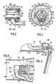
- the apparatus according to FIGS. 1 to 4 comprises: - A body (1) forming the outer envelope of the device, and generally having the shape of a pistol; - ventilation means (2) arranged inside the body (1), making it possible to generate an air flow, circulating in the device according to the arrows identified by the reference numeral (3); - a gas burner (4), of the catalytic type, arranged inside the body (1), the combustion fumes of which mix with the fresh air introduced by means of ventilation, to produce the exhausted hot air of the device; - a metal block (6) mounted inside the body (1), ensuring the passage of pressurized combustible gas from an interchangeable cartridge (7) to the burner (4); - a source (8) of electrical supply, for example a simple battery or a rechargeable accumulator, disposed inside the body (1), ensuring the electrical supply of the various organs of the apparatus requiring such a source of energy.
- the body (1) made of plastic for example, has two parts arranged substantially at right angles, namely a first part (9) forming a duct for circulation of the air flow, from the rear to the front of the apparatus, the rear part of said duct having a wider section than that of the front part, and a second part (10) having the shape of a tube, serving both for receiving the fuel gas cartridge (7) and gripping the device by the hand of the user.
- a protective grid (11) is disposed at the rear of the conduit (9), while a diffuser (12) is disposed at the front of the same conduit.
- the lower part of the tube (10) is associated with a cover (12), which can be secured reversibly by a bayonet mechanism (13).
- This cover (12) has a spring (14) for pressing the cartridge (7) against the metal block (6).
- the interchangeable cartridge (7) that is to say which can be replaced by a full cartridge when it is empty, contains a pressurized combustible gas, for example butane; it is for example an aerosol type cartridge, as described in French patent FR-A-2 580 376 in the name of the Applicant.
- the metal block (6) fixed inside the conduit (9) by suitable means comprises on the one hand reversible connection means (not shown) with the cartridge (7), allowing everything to once a tight connection with the aerosol valve and its opening, and on the other hand, control means not shown, making it possible to open or close the circulation of combustible gas towards the catalytic burner (4), and / or to regulate the debit sent to the latter.
- the block (6) comprises circulation channels (6a) of pressurized gas.
- the ventilation means (2) are arranged at the rear of the duct (9), by any suitable means, and conventionally comprise an electric motor (15) driving a fan wheel (16) opposite the protective grid (11).
- the electric motor (15) is supplied by an appropriate source, in the form of the accumulator or electric battery (8), with means for opening and closing the electric supply circuit described below.
- the catalytic burner (4) is of the induced air type, and generally comprises: a distribution chamber (116) of the mixture of combustible gas and of the oxidizing primary air, of which different inlets (16a) each communicate, as described below, with the source of pressurized fuel gas, that is to say say with the aerosol valve of the cartridge (7); - A catalytic structure (17), the inlet face (17a) of which is in relation to the aforementioned distribution chamber, in this case via an ignition chamber (18), and the face of which outlet (17b) is related to the interior of the duct (9), that is to say with the air flow circulating in the latter.
- the catalytic structure (17) comprises, on the one hand a sheet (50) of a permeable refractory support, for example a nonwoven of alumina fibers, impregnated with a combustion catalyst, and on the other hand share two wire mesh (19) and (20) with large mesh, enclosing the sheet (50).
- This structure (17), having the embodiment described above, is arranged and shaped essentially according to a tube whose axis is identical or parallel to the direction of the conduit (9).
- the catalytic structure (17) does not have a completely tubular shape, since there exists in the latter a lower opening, generally rectangular and narrow, delimited by two generatrices of the tube in question.
- This opening is closed by a rectangular plate (21), of shape and dimensions corresponding to the aforementioned opening, ensuring as described below the distribution from below of the combustible mixture.
- This plate (21) elongated in the direction of the conduit is secured to the structure (17), by means of two edges of the latter pressed against two opposite edges of the plate (21), according to the two generators mentioned above by tie rods (22) passing through said plate, and each arranged perpendicular to the direction of the conduit (9).
- This plate (21) or distribution base has a central and longitudinal channel (21a), making it possible to distribute and distribute the combustible mixture, communicating on one side with the means (30) of admixing the primary air to the combustible gas. , described below, and on the other side with different slots each forming an inlet (16a) in the distribution chamber (16).
- the catalytic burner (4) further comprises an internal partition (42) having essentially a tubular shape, arranged essentially at a distance from the catalytic structure (17), and dividing the interior of the latter into two chambers, namely on the one hand the ignition chamber (18) between the partition (42) and the catalytic structure (17), and on the other hand the distribution chamber (16) limited towards the outside of the burner by the partition ( 42).
- These chambers (16) and (18) communicate with each other, taking into account suitable orifices provided in the partition (42), or the permeability of the latter.
- the tubular internal partition (42) has, like the structure (17), an opening (42a), in correspondence with the opening (17c), delimited by two generatices, and closed by the distribution plate (21).
- the partition (42) also has two external edges not shown, clamped by the tie rods (22) between the edges of the structure (17) and the two straight edges of the plate (21).
- a spark plug (23) for example in the form of an ignition resistance of the fuel mixture, is arranged inside the ignition chamber (22).
- An internal tube (24) is arranged inside and at a distance from the catalytic structure (17), the axis of this tube being identical or parallel to the direction of the conduit (9).
- This tube (24) is supported by two transverse plates (25) and (26), disposed respectively on the downstream face and on the upstream face of the catalytic burner (4), according to the direction of movement of the arrows (3), these plates extending transversely, that is to say perpendicular to the direction of the conduit (9).
- the plates (25) and (26) each have an external shoulder for the support of the partition (42), and an internal shoulder for the support of the tube (24). As indicated Figure (2), each of these plates, fixed on the distribution base (21), extends radially between the catalytic structure (17) and the internal tube (24).
- the plate (26) also extends outside the catalytic structure (17) to form a flange for deflection of the air flow circulating in the duct (9), upstream of the burner catalytic (4). Consequently, the projection of the external contour of the burner (4), that is to say of the structure (17), in the direction of the duct (9), on the flange, is inscribed completely inside this latest.
- the interior of the catalytic structure (17) is divided, from the exterior towards the interior, into the ignition chamber (18), the distribution chamber (16), and the internal conduit (24). Thanks to the latter, the air flow circulating in the duct (9) passes not only outside the catalytic burner (17), but also from the latter, from its upstream face to its downstream face. This circulation of air inside the catalytic burner (4) makes it possible to effectively cool the latter, given the relatively high operating temperatures and characterizing any catalytic combustion with induced air.
- the means for admixing primary air to the combustible gas are arranged upstream of the distribution chamber (16), and communicate more particularly with the distribution channel (21a) of the plate (21) by the connection conduit (27).
- the admixing means (30) is located entirely inside the duct (9), and consequently the member (28) of sampling consists of an insulation casing with respect to the duct (9), connecting in a relatively leaktight manner the upstream end of the connecting duct (27) and one end of the metal block (6) comprising an injector (29).
- the internal volume of the cowling (28), ensuring the introduction of primary air communicates directly with the outside of the duct (9), through an extraction opening or opening (31) provided in the latter.
- the admixing means (30) therefore include: the injector (29) ejecting a gaseous jet of the pressurized combustible gas, from the current flowing and controlled in the block (6), - the upstream end (27a) of the connecting tube (27), having a divergent internal shape, like a venturi, arranged at a distance and in the axis of ejection of the injector (29); - the cowling (28) delimiting the space for introducing the primary air towards the outside of the connection duct (27), between its upstream end (27a) and the injector (29); this cowling (28) isolates the interior of the duct (9) from the aforementioned space for introducing primary air, which communicates with the exterior of the duct (9), through the opening (31) provided in the body (1); the cowling (28) therefore comprises two opposite perforations, allowing a relatively sealed connection with the upstream end (27a) of the tube (27) on the one hand, and with the end of the body (6) comprising the injector (29) on
- thermosensitive element (32) is disposed on the flange (26), in heat exchange relationship with the catalytic burner (4).
- This element controls the electrical supply circuit of the motor (15), this circuit being open or closed at a predetermined temperature reached by the temperature-sensitive element.
- the fan (13) starts operating, when the catalytic burner has reached the predetermined temperature, which allows the latter to rise faster in temperature, when the appliance starts.
- the fan allows rapid cooling of the latter, before the user stops using his appliance.
- the catalytic structure (17) consists of two identical cores (61) and (62), refractory and permeable, separated from each other by an ignition gap (63).
- the electrical ignition means (23) consisting in the present case of two electrodes facing each other.
- Each refractory core (61) or (62) is traversed from its inlet face to its outlet face, according to the direction of circulation of the mixture to be burned, by a plurality of parallel channels (64), each elongated in the direction of the circulation duct (9), the internal surface of which is coated with a combustion catalyst.
- These catalysts are well known in the art, under the name of "honeycomb" structure.
- the circulation of the mixture to be burned is carried out successively through the first core (61) then the second core (62), the inlet face of the first constituting the inlet face (17a) of the catalytic structure, and the exit face of the second core constituting the exit face (17b) of the same structure.
- the inlet face (17a) of the catalytic structure is arranged opposite the outlet (12) of the duct (9), whereby the distribution chamber (16) is located at the rear of the burner catalytic, according to the direction of the gas flow in the conduit (9);
- a reflector (65) is arranged opposite the outlet face (17b) of the catalytic structure, so as to thermally protect the engine (15).
- FIG. 6 differs from that described with reference to FIGS. 1 to 4, by the following points.
- the catalytic structure (17) is of the type described with reference to FIG. 5, and consequently comprises two refractory cores, permeable, not shown, separated by an ignition gap.
- the connecting conduit (27) between the distribution chamber (16) and the injector (29) is arranged transversely with respect to the conduit (9), parallel to the cartridge (7).
- the admixing means (30), comprising the injector (29), as well as the upstream end (27a) of the venturi-shaped tube (27), is located outside of the duct (9).
- the metal block (6) is divided into two parts, (6c) located inside the duct (9), and (6b) located outside the duct (9), comprising the injector ( 29), and protected by a plastic cover (71) allowing ambient air to pass.
- Such a mechanism therefore makes it possible to modulate the primary air flow, according to the operating temperature, and in particular to enrich the mixture to be burned with combustible gas, at the time of ignition.
- the catalytic burner (4) shown in Figure (7) differs from that shown in Figures 2 and 3 by the following points.
- the catalytic structure (17) comprises a sheet (50) constituted by a homogeneous entanglement of ceramic fibers, having the cohesion and flexibility of a paper, and traversed from its entry face (17a) to its exit face (17b ) by a plurality of perforations (70) distributed along the surface of the sheet.
- a sheet (50) constituted by a homogeneous entanglement of ceramic fibers, having the cohesion and flexibility of a paper, and traversed from its entry face (17a) to its exit face (17b ) by a plurality of perforations (70) distributed along the surface of the sheet.
- This catalytic structure is arranged flat and in a median plane of a rectangular box (83), parallel to the direction of the conduit (9), delimiting on either side, the distribution chamber (16) and a chamber ignition (84).
- the housing (83) has an opening (83a), protected by an anti-flame mesh, directed towards the outlet (12) of the duct (9), and in relation only with the downstream chamber (84) of the burner. Through this opening (83a), the combustion gases escape and mix with the flow of ventilated air.
Landscapes
- Engineering & Computer Science (AREA)
- Chemical & Material Sciences (AREA)
- Combustion & Propulsion (AREA)
- Mechanical Engineering (AREA)
- General Engineering & Computer Science (AREA)
- Physics & Mathematics (AREA)
- Thermal Sciences (AREA)
- Chemical Kinetics & Catalysis (AREA)
- Gas Burners (AREA)
Priority Applications (1)
| Application Number | Priority Date | Filing Date | Title |
|---|---|---|---|
| AT89420422T ATE77876T1 (de) | 1988-10-28 | 1989-10-27 | Warmlufterzeugungsvorrichtung mit einem katalytischen brenner. |
Applications Claiming Priority (2)
| Application Number | Priority Date | Filing Date | Title |
|---|---|---|---|
| FR8815370A FR2638514B1 (fr) | 1988-10-28 | 1988-10-28 | Appareil generateur d'air chaud, comportant un bruleur catalytique |
| FR8815370 | 1988-10-28 |
Publications (2)
| Publication Number | Publication Date |
|---|---|
| EP0367695A1 true EP0367695A1 (de) | 1990-05-09 |
| EP0367695B1 EP0367695B1 (de) | 1992-07-01 |
Family
ID=9372218
Family Applications (1)
| Application Number | Title | Priority Date | Filing Date |
|---|---|---|---|
| EP89420422A Expired - Lifetime EP0367695B1 (de) | 1988-10-28 | 1989-10-27 | Warmlufterzeugungsvorrichtung mit einem katalytischen Brenner |
Country Status (6)
| Country | Link |
|---|---|
| US (1) | US5009592A (de) |
| EP (1) | EP0367695B1 (de) |
| JP (1) | JPH02247409A (de) |
| AT (1) | ATE77876T1 (de) |
| DE (1) | DE68901963T2 (de) |
| FR (1) | FR2638514B1 (de) |
Cited By (4)
| Publication number | Priority date | Publication date | Assignee | Title |
|---|---|---|---|---|
| GB2254913A (en) * | 1991-04-16 | 1992-10-21 | Anthony Michael Edwards | Portable space heating device |
| FR2839545A1 (fr) * | 2002-05-10 | 2003-11-14 | Ludovic Chochoy | Chalumeau a air prechauffe |
| WO2003098109A1 (fr) * | 2002-05-10 | 2003-11-27 | Ludovic Chochoy | Chalumeau et dispositif permettant de former un chalumeau |
| IT202000012529A1 (it) * | 2020-05-27 | 2021-11-27 | Carlo Boschetto | Dispositivo accenditore a distanza |
Families Citing this family (26)
| Publication number | Priority date | Publication date | Assignee | Title |
|---|---|---|---|---|
| USD328004S (en) | 1990-10-29 | 1992-07-21 | Baltic Peter P | Fire starting device |
| US5313931A (en) * | 1991-11-20 | 1994-05-24 | Newell Operating Company | One hand fixed temperature coating remover |
| US5344314A (en) * | 1993-04-09 | 1994-09-06 | Shrinkfast Marketing | Turbine device for hot air generation |
| US5649824A (en) * | 1995-02-21 | 1997-07-22 | Stagg; Stanley E. | Portable heating device |
| US6058944A (en) * | 1999-03-16 | 2000-05-09 | Porter; Katherine | Combustion heated hair dryer |
| EP1327105A1 (de) * | 2000-10-16 | 2003-07-16 | OGLESBY & BUTLER, RESEARCH & DEVELOPMENT LIMITED | Betätigungsmechanismus zum sequentiellen betrieb von einem brenngasventil und einer zündvorrichtung und gasbetriebenes gerät mit einem solchen mechanismus |
| JP4050001B2 (ja) * | 2001-02-09 | 2008-02-20 | 株式会社 リーテック | ガス燃焼式のヘアードライヤー |
| US6497571B1 (en) | 2001-04-20 | 2002-12-24 | Teledyne Energy Systems, A Division Of Teledyne | Durable catalytic burner system |
| US20040216322A1 (en) * | 2001-12-06 | 2004-11-04 | Nicholas Collier | Hairdryer |
| EP1450642A2 (de) | 2001-12-06 | 2004-09-01 | Freedom Innovations Limited | Haarfön |
| AU2003295090A1 (en) * | 2002-12-06 | 2004-06-30 | Freedom Innovations Limited | Hairdryer |
| US20060194160A1 (en) * | 2003-03-10 | 2006-08-31 | Shinji Kokuo | Gas combustion-control method and gas combustion device |
| DE102004006515A1 (de) | 2004-02-10 | 2005-08-25 | Voith Paper Patent Gmbh | Verfahren zur Beheizung einer Walze |
| DE102004027551B4 (de) * | 2004-06-04 | 2006-06-01 | J. Wagner Gmbh | Spritzpistole |
| US6983550B1 (en) * | 2004-07-26 | 2006-01-10 | Arlo Lin | Gas hot air gun |
| DE102005015019A1 (de) * | 2005-04-01 | 2006-10-05 | Lin, Arlo, Road Town | Gas-Heißluftpistole |
| US9182144B2 (en) * | 2012-03-02 | 2015-11-10 | Pro-Iroda Industries, Inc. | Hot air blower |
| US20130228232A1 (en) * | 2012-03-02 | 2013-09-05 | Pro-Iroda Industries, Inc. | Hot Air Blower |
| DE102012014327A1 (de) * | 2012-07-12 | 2014-01-16 | Pierre Meyers | Enteisungsgerät für Automobile |
| KR101356776B1 (ko) * | 2013-05-16 | 2014-01-27 | 주식회사 코베아 | 휴대용 버너 |
| GB2556840A (en) * | 2015-10-01 | 2018-06-06 | David & D Ltd | Hot air blower and blowing method |
| US9957680B1 (en) | 2015-11-10 | 2018-05-01 | Kyle Bargoot | Handheld snow melter |
| CN109414141B (zh) * | 2016-07-15 | 2021-03-12 | 三菱电机株式会社 | 电动吸尘器及干手器 |
| CN110440438A (zh) * | 2018-05-03 | 2019-11-12 | 创科(澳门离岸商业服务)有限公司 | 空气加热器 |
| US10856638B2 (en) | 2018-05-08 | 2020-12-08 | Helen Of Troy | Hair styling appliance with directional air flow valve and compressed gas |
| DE102019100850A1 (de) * | 2019-01-14 | 2020-07-16 | Steinel Gmbh | Heißluftgebläse und Verfahren zum Betreiben desselben |
Citations (3)
| Publication number | Priority date | Publication date | Assignee | Title |
|---|---|---|---|---|
| US3995991A (en) * | 1975-12-15 | 1976-12-07 | David Bruce Wilkinson | Forced air heater |
| GB2167546A (en) * | 1984-11-22 | 1986-05-29 | Matsushita Electric Works Ltd | Portable blow heater |
| DE3614059A1 (de) * | 1985-04-27 | 1987-01-08 | Nakajima Dokosho Kk | Vorrichtung zur erzeugung eines heissgasstrahls |
Family Cites Families (9)
| Publication number | Priority date | Publication date | Assignee | Title |
|---|---|---|---|---|
| US3306335A (en) * | 1964-11-03 | 1967-02-28 | Charles H Myers | Gas space heater |
| JPS44717Y1 (de) * | 1965-07-22 | 1969-01-13 | ||
| US3301308A (en) * | 1965-09-08 | 1967-01-31 | Master Cons Inc | Safety control for portable heaters and like equipment |
| JPS4528331Y1 (de) * | 1965-11-05 | 1970-10-31 | ||
| DE3103843A1 (de) * | 1981-02-05 | 1982-09-02 | Berthold 5820 Gevelsberg Baldering | "handgeraet zum haartrocknen" |
| BR8208062A (pt) * | 1981-08-14 | 1984-01-10 | Edward Rex Raccah | Aparelho secador de cabelos |
| US4573912A (en) * | 1984-06-26 | 1986-03-04 | Itt Corporation | Space heater |
| GB2170705A (en) * | 1984-10-20 | 1986-08-13 | Edward Desmond Bishop | Cordless hair dryer |
| US4635382A (en) * | 1986-03-10 | 1987-01-13 | Serge Bourdeau | Cordless hand held hot air hair dryer |
-
1988
- 1988-10-28 FR FR8815370A patent/FR2638514B1/fr not_active Expired - Lifetime
-
1989
- 1989-10-27 JP JP1281609A patent/JPH02247409A/ja active Pending
- 1989-10-27 EP EP89420422A patent/EP0367695B1/de not_active Expired - Lifetime
- 1989-10-27 US US07/427,496 patent/US5009592A/en not_active Expired - Fee Related
- 1989-10-27 DE DE8989420422T patent/DE68901963T2/de not_active Expired - Fee Related
- 1989-10-27 AT AT89420422T patent/ATE77876T1/de not_active IP Right Cessation
Patent Citations (3)
| Publication number | Priority date | Publication date | Assignee | Title |
|---|---|---|---|---|
| US3995991A (en) * | 1975-12-15 | 1976-12-07 | David Bruce Wilkinson | Forced air heater |
| GB2167546A (en) * | 1984-11-22 | 1986-05-29 | Matsushita Electric Works Ltd | Portable blow heater |
| DE3614059A1 (de) * | 1985-04-27 | 1987-01-08 | Nakajima Dokosho Kk | Vorrichtung zur erzeugung eines heissgasstrahls |
Non-Patent Citations (2)
| Title |
|---|
| PATENT ABSTRACTS OF JAPAN, vol. 10, no. 100 (M-470)[2157], 16 avril 1986; & JP-A-60 233 415 (MATSUSHITA) 20-11-1985 * |
| PATENT ABSTRACTS OF JAPAN, vol. 9, no. 164 (M-395)[1887], 10 juillet 1985; & JP-A-60 036 813 (TOSHIBA) 26-02-1985 * |
Cited By (5)
| Publication number | Priority date | Publication date | Assignee | Title |
|---|---|---|---|---|
| GB2254913A (en) * | 1991-04-16 | 1992-10-21 | Anthony Michael Edwards | Portable space heating device |
| FR2839545A1 (fr) * | 2002-05-10 | 2003-11-14 | Ludovic Chochoy | Chalumeau a air prechauffe |
| WO2003098109A1 (fr) * | 2002-05-10 | 2003-11-27 | Ludovic Chochoy | Chalumeau et dispositif permettant de former un chalumeau |
| IT202000012529A1 (it) * | 2020-05-27 | 2021-11-27 | Carlo Boschetto | Dispositivo accenditore a distanza |
| WO2021240562A1 (en) * | 2020-05-27 | 2021-12-02 | BOSCHETTO, Emiliano | Remote igniter device |
Also Published As
| Publication number | Publication date |
|---|---|
| DE68901963D1 (de) | 1992-08-06 |
| ATE77876T1 (de) | 1992-07-15 |
| JPH02247409A (ja) | 1990-10-03 |
| FR2638514B1 (fr) | 1991-09-27 |
| FR2638514A1 (fr) | 1990-05-04 |
| US5009592A (en) | 1991-04-23 |
| DE68901963T2 (de) | 1993-02-18 |
| EP0367695B1 (de) | 1992-07-01 |
Similar Documents
| Publication | Publication Date | Title |
|---|---|---|
| EP0367695B1 (de) | Warmlufterzeugungsvorrichtung mit einem katalytischen Brenner | |
| EP0169151B1 (de) | Tragbare Vorrichtung zum Inhalieren von befeuchteter Warmluft | |
| US4190034A (en) | Apparatus for starting and fanning a fire | |
| JP4050001B2 (ja) | ガス燃焼式のヘアードライヤー | |
| JPH0220885B2 (de) | ||
| EP0313479B1 (de) | Heizvorrichtung mit katalytischem Brenner | |
| FR2559694A1 (fr) | Appareil de traitement thermique a gaz liquefie, notamment sous forme d'un fer a souder | |
| FR2678360A1 (fr) | Appareil de chauffage avec bruleur catalytique. | |
| EP0235055A1 (de) | Heisskleber-Pistole mit Gasbrenner | |
| FR3131515A1 (fr) | Appareil de coiffure a chauffage et diffusion de vapeur | |
| EP0860212A1 (de) | Auftragsgerät für Heissschmelzkleber und Kleberstift für diesen Gerät | |
| CN112335936A (zh) | 一种用于低温卷烟的加热装置 | |
| CN210747275U (zh) | 一种抽吸装置 | |
| US4890395A (en) | Hair dryer | |
| EP0059137B1 (de) | Zündvorrichtung für Brennstoff, der in einem schnellströmenden Gasstrom eingespritzt wird | |
| FR2536508A1 (fr) | Bruleur a gazeification pour carburant liquide, muni d'une zone d'incandescence a la sortie d'une chambre de gazeification | |
| FR2536505A1 (fr) | Bruleur a gazeification pour combustibles liquides | |
| FR2536506A1 (fr) | Dispositif de preparation de combustible, susceptible d'etre porte a temperature elevee, en particulier pour bruleurs a gazeification alimentes en combustible liquide, et procede de fabrication du dispositif | |
| FR2654192A1 (fr) | Appareil chauffant a gaz, avec bruleur catalytique et organe de regulation. | |
| FR2639093A1 (fr) | Appareil chauffant avec bruleur catalytique | |
| FR2573518A1 (fr) | Appareil de chauffage soufflant portatif | |
| FR2949540A3 (fr) | Cheminee | |
| FR2727191A1 (fr) | Appareil de chauffage avec bruleur catalytique, notamment rechaud de cuisson | |
| FR2503847A1 (fr) | Generateur d'air chaud a chauffage mixte gaz-electricite | |
| CA2468393A1 (en) | Hairdryer |
Legal Events
| Date | Code | Title | Description |
|---|---|---|---|
| PUAI | Public reference made under article 153(3) epc to a published international application that has entered the european phase |
Free format text: ORIGINAL CODE: 0009012 |
|
| AK | Designated contracting states |
Kind code of ref document: A1 Designated state(s): AT BE CH DE ES FR GB GR IT LI LU NL SE |
|
| 17P | Request for examination filed |
Effective date: 19900924 |
|
| 17Q | First examination report despatched |
Effective date: 19910926 |
|
| GRAA | (expected) grant |
Free format text: ORIGINAL CODE: 0009210 |
|
| AK | Designated contracting states |
Kind code of ref document: B1 Designated state(s): AT BE CH DE ES FR GB GR IT LI LU NL SE |
|
| PG25 | Lapsed in a contracting state [announced via postgrant information from national office to epo] |
Ref country code: IT Free format text: LAPSE BECAUSE OF FAILURE TO SUBMIT A TRANSLATION OF THE DESCRIPTION OR TO PAY THE FEE WITHIN THE PRE;WARNING: LAPSES OF ITALIAN PATENTS WITH EFFECTIVE DATE BEFORE 2007 MAY HAVE OCCURRED AT ANY TIME BEFORE 2007. THE CORRECT EFFECTIVE DATE MAY BE DIFFERENT FROM THE ONE RECORDED.SCRIBED TIME-LIMIT Effective date: 19920701 Ref country code: SE Effective date: 19920701 Ref country code: ES Free format text: THE PATENT HAS BEEN ANNULLED BY A DECISION OF A NATIONAL AUTHORITY Effective date: 19920701 Ref country code: GR Free format text: LAPSE BECAUSE OF FAILURE TO SUBMIT A TRANSLATION OF THE DESCRIPTION OR TO PAY THE FEE WITHIN THE PRESCRIBED TIME-LIMIT Effective date: 19920701 Ref country code: NL Effective date: 19920701 Ref country code: AT Effective date: 19920701 |
|
| REF | Corresponds to: |
Ref document number: 77876 Country of ref document: AT Date of ref document: 19920715 Kind code of ref document: T |
|
| RIN1 | Information on inventor provided before grant (corrected) |
Inventor name: ROLDAN, ANTOINE Inventor name: DEMILLIERE-VERGNAIS, DANIEL |
|
| GBT | Gb: translation of ep patent filed (gb section 77(6)(a)/1977) | ||
| REF | Corresponds to: |
Ref document number: 68901963 Country of ref document: DE Date of ref document: 19920806 |
|
| PG25 | Lapsed in a contracting state [announced via postgrant information from national office to epo] |
Ref country code: LU Free format text: LAPSE BECAUSE OF NON-PAYMENT OF DUE FEES Effective date: 19921031 Ref country code: BE Effective date: 19921031 Ref country code: CH Effective date: 19921031 Ref country code: LI Effective date: 19921031 |
|
| NLV1 | Nl: lapsed or annulled due to failure to fulfill the requirements of art. 29p and 29m of the patents act | ||
| BERE | Be: lapsed |
Owner name: APPLICATION DES GAZ Effective date: 19921031 |
|
| PLBE | No opposition filed within time limit |
Free format text: ORIGINAL CODE: 0009261 |
|
| STAA | Information on the status of an ep patent application or granted ep patent |
Free format text: STATUS: NO OPPOSITION FILED WITHIN TIME LIMIT |
|
| 26N | No opposition filed | ||
| REG | Reference to a national code |
Ref country code: CH Ref legal event code: PL |
|
| PGFP | Annual fee paid to national office [announced via postgrant information from national office to epo] |
Ref country code: FR Payment date: 19941013 Year of fee payment: 6 |
|
| PGFP | Annual fee paid to national office [announced via postgrant information from national office to epo] |
Ref country code: GB Payment date: 19941018 Year of fee payment: 6 |
|
| PGFP | Annual fee paid to national office [announced via postgrant information from national office to epo] |
Ref country code: DE Payment date: 19941202 Year of fee payment: 6 |
|
| PG25 | Lapsed in a contracting state [announced via postgrant information from national office to epo] |
Ref country code: GB Effective date: 19951027 |
|
| GBPC | Gb: european patent ceased through non-payment of renewal fee |
Effective date: 19951027 |
|
| PG25 | Lapsed in a contracting state [announced via postgrant information from national office to epo] |
Ref country code: FR Effective date: 19960628 |
|
| PG25 | Lapsed in a contracting state [announced via postgrant information from national office to epo] |
Ref country code: DE Effective date: 19960702 |
|
| REG | Reference to a national code |
Ref country code: FR Ref legal event code: ST |