EP0367760B1 - Rotable apparatus comprising permanent magnets - Google Patents
Rotable apparatus comprising permanent magnets Download PDFInfo
- Publication number
- EP0367760B1 EP0367760B1 EP19880901552 EP88901552A EP0367760B1 EP 0367760 B1 EP0367760 B1 EP 0367760B1 EP 19880901552 EP19880901552 EP 19880901552 EP 88901552 A EP88901552 A EP 88901552A EP 0367760 B1 EP0367760 B1 EP 0367760B1
- Authority
- EP
- European Patent Office
- Prior art keywords
- rotable
- permanent magnets
- rotor
- magnets
- fact
- Prior art date
- Legal status (The legal status is an assumption and is not a legal conclusion. Google has not performed a legal analysis and makes no representation as to the accuracy of the status listed.)
- Expired - Lifetime
Links
- 230000005415 magnetization Effects 0.000 claims abstract description 4
- 230000032683 aging Effects 0.000 abstract 1
- 239000002131 composite material Substances 0.000 abstract 1
- 230000005611 electricity Effects 0.000 abstract 1
- 230000005284 excitation Effects 0.000 abstract 1
- 230000010287 polarization Effects 0.000 abstract 1
- 230000005417 remagnetization Effects 0.000 abstract 1
- 239000000463 material Substances 0.000 description 2
- 125000006850 spacer group Chemical group 0.000 description 2
- 230000008878 coupling Effects 0.000 description 1
- 238000010168 coupling process Methods 0.000 description 1
- 238000005859 coupling reaction Methods 0.000 description 1
- 230000005520 electrodynamics Effects 0.000 description 1
- 230000008030 elimination Effects 0.000 description 1
- 238000003379 elimination reaction Methods 0.000 description 1
- 230000006698 induction Effects 0.000 description 1
- 238000011835 investigation Methods 0.000 description 1
- 239000000696 magnetic material Substances 0.000 description 1
- 230000005389 magnetism Effects 0.000 description 1
Images
Classifications
-
- H—ELECTRICITY
- H02—GENERATION; CONVERSION OR DISTRIBUTION OF ELECTRIC POWER
- H02K—DYNAMO-ELECTRIC MACHINES
- H02K53/00—Alleged dynamo-electric perpetua mobilia
Definitions
- the invention relates to a rotating device with permanent magnets (see e.g. US-A-4 600 849).
- the invention has for its object to provide a device for the experimental investigation of magnetism. This object is solved by the features of claim 1.
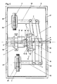
- Fig. 1 shows the side view of an embodiment of the device according to the invention. Specifically, in this embodiment, it is alternatively possible to arrange the axis of rotation (4) horizontally through a 90 o -Schwenkung the frame (3) or vertically.
- the frame (3) consists of mutually facing L-profiles. Two complete rectangular frame connections are congruently connected at an intermediate distance by the connecting webs (21).
- the central stand (17) is screwed in the center of the frame (3) by means of a flange (19).
- the central stand (17) consists of two parts screwed together.
- the central stator magnet (1) is clamped between its upper and lower part and adjusted by thread pressure. Its lower part forms a piece with the flange (19) and ensures the exact horizontal or vertical alignment of the stator magnet (1).
- the upper part carries the lower axle bearing (12) in a central bore and the bearing sleeve (16) in a decentric, minimally oblique bore.
- the smooth-running axial control bearing (13) is located between this bearing sleeve (16) and the control disk (14).
- the inclination of the control bearing (13) is permanently transferred to the rotor arms (9) via the two control levers (15), which are guided to move easily in the control joints (8).
- This level difference moves the rotor arms up and down sinusoidally for each full revolution.
- the rotor arms (9) consist of a slightly cranked U-profile, the connecting web of which is recessed to a small extent. In the central recess, the side surfaces of the profile are connected to the rotor flange (5) and the axis of rotation (4) via the rocker bearings (6).
- the parallel joints (7) are located on the outer recesses of the rotor arms (9), via which the rotor stands (10) are easily guided.
- the rotor magnet (2) is clamped and locked with a thread pressure between a collar of the rotor stands (10) and the counter disc (20).
- the axle bearing (11), which guides the axis of rotation (4) centrally, is located in the bearing flange (18).
- the extension of the axis of rotation (4) beyond the lower axle bearing (12) and the connecting webs (21) with a flat surface enable the coupling of several drive units.
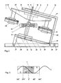
- FIG. 2 A further embodiment of the device according to the invention is shown in FIG. 2.
- the required level difference is achieved here solely by the inclination of the axis of rotation (4).
- the elimination of frictional losses through this control allows very low performance and small dimensions.
- This frame (3) also consists of L-profiles, which are designed as two congruent U-shapes to reduce material. The exact parallelism of both frame parts is also achieved here by the connecting webs (21).
- the frame (3) is raised against the horizontal rails (25) in order to achieve the axis inclination in the tilting bearing (26) and fixed in this position by means of the locking bolt (28).
- the two horizontal rails (25) form the foundation of this unit and are held in parallel by means of the spacer bolts (27).
- One of these spacer bolts (27) forms the base of the locking bolt (28), while its head part is screwed to a connecting web (21).
- the axis of rotation (4) is guided centrally through the lower axle bearing (12) in the lower flange (19) and through the upper axle bearing (11) in the upper flange (18).
- the rotor carrier (22) is connected to the axis of rotation (4) via the rotor flange (5).
- the rotor carrier (22) consists of a U-profile open at the bottom, the side legs of which are chamfered towards its ends.
- the rotor stands (10) are fastened to the connecting web of the profile and, here too, clamp the rotor magnet (2) with thread pressure between their collar and the counter disk (20).
- the foot flange of the central tilting stand (24) is screwed directly to the lower flange (19), the two outer columns of which clamp the stator support ring (23) in between, which can be locked in any inclined position.
- This stator carrier ring (23) with the stator magnet (1) pressed or glued therein is adjusted horizontally against the tilting position of the frame (3) and thus also the axis of rotation (4).
- stator permanent magnets (1) and rotor permanent magnets (2) of FIGS. 1 and 2 are magnetic rings in the magnetization shown. All other materials consist of non-magnetic material with a statically necessary strength.
- Fig. 3 shows the development of the stator magnet (1) from Fig. 2 with diametrical magnetization and the same position, and the movement curve (C) of a rotor magnet (2).
Landscapes
- Engineering & Computer Science (AREA)
- Power Engineering (AREA)
- Permanent Magnet Type Synchronous Machine (AREA)
- Manufacture Of Motors, Generators (AREA)
Abstract
Description
Die Erfindung betrifft eine Rotationsvorrichtung mit Permanentmagneten (s. z.B. US-A-4 600 849).The invention relates to a rotating device with permanent magnets (see e.g. US-A-4 600 849).
Die physikalischen Erscheinungsformen und Phänomene des Permanent- und Elektromagnetismus, insbesondere der Anziehung ungleicher- und Abstoßung gleicher Magnetpole, der Induktion und des magnetischen Feldes sind Theorien, die sich in experimentellen, elektrodynamischen und mathematischen Belegen zu Gesetzmäßigkeiten, wie z.B. von Ampère, Coulomb, Faraday, Gauß, Lenz, Lorentz, Maxwell und Oersted verdichtet haben.The physical manifestations and phenomena of permanent and electromagnetism, in particular the attraction of unequal and repulsion of the same magnetic poles, induction and the magnetic field are theories that can be found in experimental, electrodynamic and mathematical evidence on laws such as Ampère, Coulomb, Faraday , Gauss, Lenz, Lorentz, Maxwell and Oersted.
Der Erfindung liegt die Aufgabe zugrunde, eine Vorrichtung zur experimentellen Untersuchung des Magnetismus zu schaffen. Diese Aufgabe wird durch die Merkmale des Anspruchs 1 gelöst.The invention has for its object to provide a device for the experimental investigation of magnetism. This object is solved by the features of
Die Erfindung wird im folgenden anhand von zwei Ausführungsformen unter Bezugnahme auf die beigefügten Zeichnungen näher beschrieben.The invention is described below with reference to two embodiments with reference to the accompanying drawings.
Es zeigen :
- Fig. 1
- Eine erste Ausführungsform der erfindungsgemäßen Vorrichtung in einer Seitenansicht.
- Fig. 2
- Eine zweite Ausführungsform der erfindungsgemäßen Vorrichtung.
- Fig. 3
- Die Abwicklung des in Fig. 2 beteiligten Stator-Permanentmagneten mit der Bewegungskurve ( C ) eines Läufer-Permanentmagneten.
- Fig. 1
- A first embodiment of the device according to the invention in a side view.
- Fig. 2
- A second embodiment of the device according to the invention.
- Fig. 3
- The development of the stator permanent magnet involved in FIG. 2 with the movement curve (C) of a rotor permanent magnet.
Fig. 1 zeigt die Seitenansicht einer Ausführungsform der erfindungsgemäßen Vorrichtung. Speziell bei dieser Ausführung ist es wahlweise möglich, die Rotationsachse (4) durch eine 90o-Schwenkung des Rahmens (3) horizontal oder vertikal anzuordnen.Fig. 1 shows the side view of an embodiment of the device according to the invention. Specifically, in this embodiment, it is alternatively possible to arrange the axis of rotation (4) horizontally through a 90 o -Schwenkung the frame (3) or vertically.
Der Rahmen (3) besteht aus einander zugekehrten L-Profilen. Zwei komplette rechteckige Rahmenverbindungen sind mit einem Zwischenabstand durch die Verbindungsstege (21) deckungsgleich verbunden.The frame (3) consists of mutually facing L-profiles. Two complete rectangular frame connections are congruently connected at an intermediate distance by the connecting webs (21).
Mittig im Rahmen (3) ist der Zentralständer (17) mittels Flansch (19) angeschraubt. Der Zentralständer (17) besteht aus zwei miteinander verschraubten Teilen. Zwischen seinem Ober- und Unterteil ist der zentrale Statormagnet (1) eingespannt und durch Gewindedruck justiert.
Sein Unterteil bildet mit dem Flansch (19) ein Stück und sorgt für die exakt horizontale, bzw. vertikale Ausrichtung des Statormagneten (1).
Das Oberteil trägt in zentraler Bohrung das untere Achslager (12) und in dezentrisch, minimal schräger Bohrung die Lagerhülse (16).
Zwischen dieser Lagerhülse (16) und der Steuerscheibe (14) befindet sich das leichtgängige axiale Steuerlager (13). Über die zwei Steuerhebel (15), die in den Steuergelenken (8) leichtbeweglich geführt werden, wird die Neigung des Steuerlagers (13) permanent auf die Läuferarme (9) übertragen.
Diese Niveaudifferenz bewegt die Läuferarme pro einer vollen Umdrehung sinusförmig auf und ab.
Die Läuferarme (9) bestehen aus einem leicht in sich gekröpften U-Profil, dessen Verbindungssteg bis auf einen geringen Teil ausgespart ist. In der mittigen Aussparung sind die Seitenflächen des Profils über die Wipplager (6) mit dem Läuferflansch (5) und der Rotationsachse (4) verbunden.
An den äußeren Aussparungen der Läuferarme (9) befinden sich die Parallelgelenke (7), über die die Läuferständer (10) leichtgängig geführt werden.
Zwischen einem Bund der Läuferständer (10) und der Gegenscheibe (20) ist der Läufermagnet (2) mit Gewindedruck eingespannt und arretiert.The central stand (17) is screwed in the center of the frame (3) by means of a flange (19). The central stand (17) consists of two parts screwed together. The central stator magnet (1) is clamped between its upper and lower part and adjusted by thread pressure.
Its lower part forms a piece with the flange (19) and ensures the exact horizontal or vertical alignment of the stator magnet (1).
The upper part carries the lower axle bearing (12) in a central bore and the bearing sleeve (16) in a decentric, minimally oblique bore.
The smooth-running axial control bearing (13) is located between this bearing sleeve (16) and the control disk (14). The inclination of the control bearing (13) is permanently transferred to the rotor arms (9) via the two control levers (15), which are guided to move easily in the control joints (8).
This level difference moves the rotor arms up and down sinusoidally for each full revolution.
The rotor arms (9) consist of a slightly cranked U-profile, the connecting web of which is recessed to a small extent. In the central recess, the side surfaces of the profile are connected to the rotor flange (5) and the axis of rotation (4) via the rocker bearings (6).
The parallel joints (7) are located on the outer recesses of the rotor arms (9), via which the rotor stands (10) are easily guided.
The rotor magnet (2) is clamped and locked with a thread pressure between a collar of the rotor stands (10) and the counter disc (20).
Im Lagerflansch (18) befindet sich das Achslager (11), das die Rotationsachse (4) zentrisch führt.
Die Verlängerung der Rotationsachse (4) über das untere Achslager (12) hinaus, und die oberflächenplan ausgeführten Verbindungsstege (21) ermöglichen die Koppelung mehrerer Antriebseinheiten.The axle bearing (11), which guides the axis of rotation (4) centrally, is located in the bearing flange (18).
The extension of the axis of rotation (4) beyond the lower axle bearing (12) and the connecting webs (21) with a flat surface enable the coupling of several drive units.
Eine weitere Ausführungsform der erfindungsgemäßen Vorrichtung zeigt Fig. 2.A further embodiment of the device according to the invention is shown in FIG. 2.
Die erforderliche Niveaudifferenz wird hier allein durch die Neigung der Rotationsachse (4) erreicht. Der Wegfall von Reibungsverlusten durch diese Steuerung erlaubt kleinste Leistungen und geringe Abmessungen.The required level difference is achieved here solely by the inclination of the axis of rotation (4). The elimination of frictional losses through this control allows very low performance and small dimensions.
Auch dieser Rahmen (3) besteht aus L-Profilen, die hier zur Materialminderung als zwei deckungsgleiche U-Formen ausgebildet sind. Die exakte Parallelität beider Rahmenteile wird auch hier durch die Verbindungsstege (21) erreicht.This frame (3) also consists of L-profiles, which are designed as two congruent U-shapes to reduce material. The exact parallelism of both frame parts is also achieved here by the connecting webs (21).
Der Rahmen (3) ist zur Erzielung der Achsneigung im Kipplager (26) gegen die Horizontalschienen (25) angehoben und mittels des Arretierbolzens (28) in dieser Stellung fixiert.
Die zwei Horizontalschienen (25) bilden das Standfundament dieser Einheit und werden mittels der Distanzbolzen (27) parallel gehalten. Einer dieser Distanzbolzen (27) bildet den Fußpunkt des Arretierbolzens (28), während sein Kopfteil mit einem Verbindungssteg (21) verschraubt ist.The frame (3) is raised against the horizontal rails (25) in order to achieve the axis inclination in the tilting bearing (26) and fixed in this position by means of the locking bolt (28).
The two horizontal rails (25) form the foundation of this unit and are held in parallel by means of the spacer bolts (27). One of these spacer bolts (27) forms the base of the locking bolt (28), while its head part is screwed to a connecting web (21).
Die Rotationsachse (4) wird durch das untere Achslager (12) im unteren Flansch (19) und durch das obere Achslager (11) im oberen Flansch (18) zentrisch geführt.The axis of rotation (4) is guided centrally through the lower axle bearing (12) in the lower flange (19) and through the upper axle bearing (11) in the upper flange (18).
Über den Läuferflansch (5) ist der Läuferträger (22) mit der Rotationsachse (4) verbunden. Der Läuferträger (22) besteht aus einem nach unten offenen U-Profil, dessen Seitenschenkel zu seinen Enden hin abgeschrägt sind. An dem Verbindungssteg des Profiles sind die Läuferständer (10) befestigt, die auch hier zwischen ihrem Bund und der Gegenscheibe (20) den Läufermagneten (2) mit Gewindedruck einspannen.The rotor carrier (22) is connected to the axis of rotation (4) via the rotor flange (5). The rotor carrier (22) consists of a U-profile open at the bottom, the side legs of which are chamfered towards its ends. The rotor stands (10) are fastened to the connecting web of the profile and, here too, clamp the rotor magnet (2) with thread pressure between their collar and the counter disk (20).
Direkt mit dem unteren Flansch (19) ist der Fußflansch des zentralen Kippständers (24) verschraubt, dessen zwei äußeren Säulen den dazwischenliegenden Stator-Trägerring (23) einspannen, der dadurch in jeder Schräglage arretierbar ist.
Hier ist dieser Stator-Trägerring (23) mit dem darin eingepreßten oder verklebten Statormagneten (1) gegen die Kippstellung des Rahmens (3) und damit auch der Rotationsachse (4) in der Horizontalen justiert.The foot flange of the central tilting stand (24) is screwed directly to the lower flange (19), the two outer columns of which clamp the stator support ring (23) in between, which can be locked in any inclined position.
This stator carrier ring (23) with the stator magnet (1) pressed or glued therein is adjusted horizontally against the tilting position of the frame (3) and thus also the axis of rotation (4).
Diese Horizontalstellung des Statormagneten (1) gegen die Neigung der Rotationsachse (4) ergibt die notwendige Niveaudifferenz zwischen zwei 180o-Drehhälften und damit das kontinuierliche gemeinsame gleiche Drehmoment.This horizontal position of the stator magnet (1) against the inclination of the axis of rotation (4) results in the necessary level difference between two 180 o rotating halves and thus the continuous, common torque.
Sämtliche Stator-Permanentmagnete (1) und Läufer-Permanentmagnete (2) der Fig. 1 und Fig. 2 sind Magnetringe in der dargestellten Magnetisierung. Alle sonstigen Materialien bestehen aus nichtmagnetischem Material statisch notwendiger Festigkeit.All stator permanent magnets (1) and rotor permanent magnets (2) of FIGS. 1 and 2 are magnetic rings in the magnetization shown. All other materials consist of non-magnetic material with a statically necessary strength.
Fig. 3 zeigt die Abwicklung des Statormagneten (1) aus Fig. 2 mit diametraler Magnetisierung und gleicher Position, und die Bewegungskurve (C) eines Läufermagneten (2).Fig. 3 shows the development of the stator magnet (1) from Fig. 2 with diametrical magnetization and the same position, and the movement curve (C) of a rotor magnet (2).
Claims (5)
- Rotable apparatus comprising permanent magnets in which each
of at least two rotor magnets (2) is guided on a circular path around one stator magnet (1) in such a manner that one of the rotor magnets (2) is located below a null plane which is parallel to its direction of magnetization and encloses the stator magnet (1) and the other rotor magnet (2) is above said null plane. - Rotable apparatus as described in Claim 1, characterized by
the fact that the distance of the rotor magnets (2) from the null plane can be adjusted by means of a mechanic control (5 to 9, 13 to 16). - Rotable apparatus as described in Claim 2, characterized by
the fact that the mechanical control (5 - 9, 13 - 16) has an inclined axis. - Rotable apparatus as described in Claim 1, characterized by
the fact that the distance of the rotor magnets (2) from the null plane is achieved by inclining one or more magnets (1, 2). - Rotable apparatus as described in one of Claims 1 to 4,
characterized by the fact that it is coupled to at least one additional rotable apparatus as described in one of Claims 1 to 4.
Priority Applications (2)
| Application Number | Priority Date | Filing Date | Title |
|---|---|---|---|
| DE88901552T DE3884805D1 (en) | 1988-02-12 | 1988-02-12 | Rotation device with permanent magnets. |
| AT88901552T ATE95650T1 (en) | 1988-02-12 | 1988-02-12 | ROTATION DEVICE WITH PERMANENT MAGNETS. |
Applications Claiming Priority (1)
| Application Number | Priority Date | Filing Date | Title |
|---|---|---|---|
| PCT/DE1988/000071 WO1989007857A1 (en) | 1988-02-12 | 1988-02-12 | Motor driven by permanent magnets |
Publications (2)
| Publication Number | Publication Date |
|---|---|
| EP0367760A1 EP0367760A1 (en) | 1990-05-16 |
| EP0367760B1 true EP0367760B1 (en) | 1993-10-06 |
Family
ID=6819310
Family Applications (1)
| Application Number | Title | Priority Date | Filing Date |
|---|---|---|---|
| EP19880901552 Expired - Lifetime EP0367760B1 (en) | 1988-02-12 | 1988-02-12 | Rotable apparatus comprising permanent magnets |
Country Status (2)
| Country | Link |
|---|---|
| EP (1) | EP0367760B1 (en) |
| WO (1) | WO1989007857A1 (en) |
Families Citing this family (3)
| Publication number | Priority date | Publication date | Assignee | Title |
|---|---|---|---|---|
| ITCE20080010A1 (en) * | 2008-10-23 | 2010-04-23 | Antonio Santonicola | ZERO COST ENERGY PRODUCTION DEVICE |
| CN103560707B (en) * | 2013-11-18 | 2015-10-07 | 冯福荣 | A kind of power-equipment |
| EP3969041A4 (en) | 2019-05-14 | 2023-05-10 | Taiga Biotechnologies, Inc. | COMPOSITIONS AND METHODS FOR TREATING T LYMPHOCYTE DEPLETION |
Family Cites Families (5)
| Publication number | Priority date | Publication date | Assignee | Title |
|---|---|---|---|---|
| FR604191A (en) * | 1925-01-06 | 1926-04-30 | Motor running continuously by the magnetic field of the magnets | |
| US2779885A (en) * | 1951-11-28 | 1957-01-29 | Hartford Nat Bank & Trust Co | Electrical apparatus in which a permanent magnet is included in the magnetic circuit |
| DE2029553A1 (en) * | 1970-06-16 | 1971-12-23 | Hallmann H | Device for generating permanent magnetic useful energy |
| US4598221A (en) * | 1985-01-23 | 1986-07-01 | Lawson William J | Permanent magnet motor having rockable rotor magnets |
| US4600849A (en) * | 1985-01-23 | 1986-07-15 | Lawson William J | Fluid-activated motor having magnetic propulsion |
-
1988
- 1988-02-12 WO PCT/DE1988/000071 patent/WO1989007857A1/en not_active Ceased
- 1988-02-12 EP EP19880901552 patent/EP0367760B1/en not_active Expired - Lifetime
Also Published As
| Publication number | Publication date |
|---|---|
| EP0367760A1 (en) | 1990-05-16 |
| WO1989007857A1 (en) | 1989-08-24 |
Similar Documents
| Publication | Publication Date | Title |
|---|---|---|
| EP0899855B1 (en) | Rotary device with magnetic bearing | |
| DE69309444T2 (en) | BRUSHLESS DC MOTOR / GENERATOR | |
| DE2730142C2 (en) | Brushless DC motor of the two-strand design | |
| EP0691727B1 (en) | Electric motor excited by the use of permanent magnets, particularly for inner rotor or outer rotor motor | |
| WO2002018794A1 (en) | Vacuum pump | |
| DE2208034A1 (en) | Self-aligning bearing using permanent magnets | |
| EP0207535B1 (en) | Single-phase synchronous motor with a bipolar permanent-magnet excited rotor | |
| WO2005048437A1 (en) | Drive unit for generating an oscillatory motion for electrical small-scale units | |
| DE102005042543A1 (en) | Permanent-magnet synchronous machine for slowly rotating wind power plant, has counterpart provided as fastening part at magnet wheel, which is formed from two disk-shaped units and aligned bars that run axially perpendicular | |
| DE3730615A1 (en) | ELECTRICAL MACHINE WITH PERMANENT MAGNETIC EXCITATION | |
| EP0367760B1 (en) | Rotable apparatus comprising permanent magnets | |
| DE102011115162A1 (en) | Eddy current brake for use with vehicles, has rotor comprising brake drum, rotatable guide pipe that is in limited rotation in circumferential direction, and non-rotatable guide pipe that is not rotatable in circumferential direction | |
| DE3931611A1 (en) | Rotational force intensifier using permanent magnets - maintaining torque and RPM by aligned and directed magnetic fields with motor or muscle power starting | |
| DE102009043614A1 (en) | Electromagnetic unit for use in ring coil motor of e.g. robot, has stator-magnet tooth arrangement with tooth, and rotor-magnet tooth arrangement and/or rotor-magnet pole facing stator-magnet tooth arrangement | |
| DE10334594A1 (en) | electric motor | |
| EP0313764A2 (en) | Energy conversion device | |
| DE102013003786A1 (en) | Apparatus for generating energy by using the attraction and repulsion forces of permanent magnets | |
| DE20211510U1 (en) | Magnetic bearing for e.g. shaft bearings in vacuum pump, includes magnet on fixed bearing part to compensate for attraction between yoke and permanent magnet on rotary bearing part | |
| DE102019200526A1 (en) | Storage device and method | |
| DE3908313A1 (en) | Commutatorless permanent-magnet DC motor | |
| DE3016540A1 (en) | Rotary inductor for electrical machine - has permanent magnet rotors with magnets arranged radially with intermediate tapered pole pieces | |
| CH699130A2 (en) | Magnetic spin motor. | |
| EP3679641B1 (en) | Rotating electric machine | |
| EP0543031A1 (en) | Permanent magnet motors | |
| DE102017011734A1 (en) | Permanent magnet motor with double maltese cross gear |
Legal Events
| Date | Code | Title | Description |
|---|---|---|---|
| PUAI | Public reference made under article 153(3) epc to a published international application that has entered the european phase |
Free format text: ORIGINAL CODE: 0009012 |
|
| 17P | Request for examination filed |
Effective date: 19900213 |
|
| AK | Designated contracting states |
Kind code of ref document: A1 Designated state(s): AT BE CH DE FR GB IT LI LU NL SE |
|
| 17Q | First examination report despatched |
Effective date: 19920129 |
|
| GRAA | (expected) grant |
Free format text: ORIGINAL CODE: 0009210 |
|
| AK | Designated contracting states |
Kind code of ref document: B1 Designated state(s): AT BE CH DE FR GB IT LI LU NL SE |
|
| PG25 | Lapsed in a contracting state [announced via postgrant information from national office to epo] |
Ref country code: IT Free format text: LAPSE BECAUSE OF FAILURE TO SUBMIT A TRANSLATION OF THE DESCRIPTION OR TO PAY THE FEE WITHIN THE PRE;WARNING: LAPSES OF ITALIAN PATENTS WITH EFFECTIVE DATE BEFORE 2007 MAY HAVE OCCURRED AT ANY TIME BEFORE 2007. THE CORRECT EFFECTIVE DATE MAY BE DIFFERENT FROM THE ONE RECORDED.SCRIBED TIME-LIMIT Effective date: 19931006 Ref country code: FR Effective date: 19931006 Ref country code: SE Effective date: 19931006 Ref country code: BE Effective date: 19931006 |
|
| REF | Corresponds to: |
Ref document number: 95650 Country of ref document: AT Date of ref document: 19931015 Kind code of ref document: T |
|
| REF | Corresponds to: |
Ref document number: 3884805 Country of ref document: DE Date of ref document: 19931111 |
|
| PGFP | Annual fee paid to national office [announced via postgrant information from national office to epo] |
Ref country code: SE Payment date: 19940215 Year of fee payment: 7 |
|
| GBT | Gb: translation of ep patent filed (gb section 77(6)(a)/1977) |
Effective date: 19940118 |
|
| EN | Fr: translation not filed | ||
| ITTA | It: last paid annual fee | ||
| PG25 | Lapsed in a contracting state [announced via postgrant information from national office to epo] |
Ref country code: LU Free format text: LAPSE BECAUSE OF NON-PAYMENT OF DUE FEES Effective date: 19940228 |
|
| PLBE | No opposition filed within time limit |
Free format text: ORIGINAL CODE: 0009261 |
|
| STAA | Information on the status of an ep patent application or granted ep patent |
Free format text: STATUS: NO OPPOSITION FILED WITHIN TIME LIMIT |
|
| 26N | No opposition filed | ||
| PGFP | Annual fee paid to national office [announced via postgrant information from national office to epo] |
Ref country code: DE Payment date: 19950213 Year of fee payment: 8 |
|
| PGFP | Annual fee paid to national office [announced via postgrant information from national office to epo] |
Ref country code: GB Payment date: 19950214 Year of fee payment: 8 |
|
| PGFP | Annual fee paid to national office [announced via postgrant information from national office to epo] |
Ref country code: AT Payment date: 19950223 Year of fee payment: 8 Ref country code: CH Payment date: 19950223 Year of fee payment: 8 |
|
| PGFP | Annual fee paid to national office [announced via postgrant information from national office to epo] |
Ref country code: NL Payment date: 19950228 Year of fee payment: 8 |
|
| PG25 | Lapsed in a contracting state [announced via postgrant information from national office to epo] |
Ref country code: GB Effective date: 19960212 Ref country code: AT Effective date: 19960212 |
|
| PG25 | Lapsed in a contracting state [announced via postgrant information from national office to epo] |
Ref country code: LI Effective date: 19960229 Ref country code: CH Effective date: 19960229 |
|
| PG25 | Lapsed in a contracting state [announced via postgrant information from national office to epo] |
Ref country code: NL Effective date: 19960901 |
|
| GBPC | Gb: european patent ceased through non-payment of renewal fee |
Effective date: 19960212 |
|
| REG | Reference to a national code |
Ref country code: CH Ref legal event code: PL |
|
| NLV4 | Nl: lapsed or anulled due to non-payment of the annual fee |
Effective date: 19960901 |
|
| PG25 | Lapsed in a contracting state [announced via postgrant information from national office to epo] |
Ref country code: DE Effective date: 19961101 |