EP0367760B1 - Dispositif rotatif comprenant des aimants permanents - Google Patents
Dispositif rotatif comprenant des aimants permanents Download PDFInfo
- Publication number
- EP0367760B1 EP0367760B1 EP19880901552 EP88901552A EP0367760B1 EP 0367760 B1 EP0367760 B1 EP 0367760B1 EP 19880901552 EP19880901552 EP 19880901552 EP 88901552 A EP88901552 A EP 88901552A EP 0367760 B1 EP0367760 B1 EP 0367760B1
- Authority
- EP
- European Patent Office
- Prior art keywords
- rotable
- permanent magnets
- rotor
- magnets
- fact
- Prior art date
- Legal status (The legal status is an assumption and is not a legal conclusion. Google has not performed a legal analysis and makes no representation as to the accuracy of the status listed.)
- Expired - Lifetime
Links
- 230000005415 magnetization Effects 0.000 claims abstract description 4
- 230000032683 aging Effects 0.000 abstract 1
- 239000002131 composite material Substances 0.000 abstract 1
- 230000005611 electricity Effects 0.000 abstract 1
- 230000005284 excitation Effects 0.000 abstract 1
- 230000010287 polarization Effects 0.000 abstract 1
- 230000005417 remagnetization Effects 0.000 abstract 1
- 239000000463 material Substances 0.000 description 2
- 125000006850 spacer group Chemical group 0.000 description 2
- 230000008878 coupling Effects 0.000 description 1
- 238000010168 coupling process Methods 0.000 description 1
- 238000005859 coupling reaction Methods 0.000 description 1
- 230000005520 electrodynamics Effects 0.000 description 1
- 230000008030 elimination Effects 0.000 description 1
- 238000003379 elimination reaction Methods 0.000 description 1
- 230000006698 induction Effects 0.000 description 1
- 238000011835 investigation Methods 0.000 description 1
- 239000000696 magnetic material Substances 0.000 description 1
- 230000005389 magnetism Effects 0.000 description 1
Images
Classifications
-
- H—ELECTRICITY
- H02—GENERATION; CONVERSION OR DISTRIBUTION OF ELECTRIC POWER
- H02K—DYNAMO-ELECTRIC MACHINES
- H02K53/00—Alleged dynamo-electric perpetua mobilia
Definitions
- the invention relates to a rotating device with permanent magnets (see e.g. US-A-4 600 849).
- the invention has for its object to provide a device for the experimental investigation of magnetism. This object is solved by the features of claim 1.
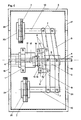
- Fig. 1 shows the side view of an embodiment of the device according to the invention. Specifically, in this embodiment, it is alternatively possible to arrange the axis of rotation (4) horizontally through a 90 o -Schwenkung the frame (3) or vertically.
- the frame (3) consists of mutually facing L-profiles. Two complete rectangular frame connections are congruently connected at an intermediate distance by the connecting webs (21).
- the central stand (17) is screwed in the center of the frame (3) by means of a flange (19).
- the central stand (17) consists of two parts screwed together.
- the central stator magnet (1) is clamped between its upper and lower part and adjusted by thread pressure. Its lower part forms a piece with the flange (19) and ensures the exact horizontal or vertical alignment of the stator magnet (1).
- the upper part carries the lower axle bearing (12) in a central bore and the bearing sleeve (16) in a decentric, minimally oblique bore.
- the smooth-running axial control bearing (13) is located between this bearing sleeve (16) and the control disk (14).
- the inclination of the control bearing (13) is permanently transferred to the rotor arms (9) via the two control levers (15), which are guided to move easily in the control joints (8).
- This level difference moves the rotor arms up and down sinusoidally for each full revolution.
- the rotor arms (9) consist of a slightly cranked U-profile, the connecting web of which is recessed to a small extent. In the central recess, the side surfaces of the profile are connected to the rotor flange (5) and the axis of rotation (4) via the rocker bearings (6).
- the parallel joints (7) are located on the outer recesses of the rotor arms (9), via which the rotor stands (10) are easily guided.
- the rotor magnet (2) is clamped and locked with a thread pressure between a collar of the rotor stands (10) and the counter disc (20).
- the axle bearing (11), which guides the axis of rotation (4) centrally, is located in the bearing flange (18).
- the extension of the axis of rotation (4) beyond the lower axle bearing (12) and the connecting webs (21) with a flat surface enable the coupling of several drive units.
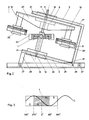
- FIG. 2 A further embodiment of the device according to the invention is shown in FIG. 2.
- the required level difference is achieved here solely by the inclination of the axis of rotation (4).
- the elimination of frictional losses through this control allows very low performance and small dimensions.
- This frame (3) also consists of L-profiles, which are designed as two congruent U-shapes to reduce material. The exact parallelism of both frame parts is also achieved here by the connecting webs (21).
- the frame (3) is raised against the horizontal rails (25) in order to achieve the axis inclination in the tilting bearing (26) and fixed in this position by means of the locking bolt (28).
- the two horizontal rails (25) form the foundation of this unit and are held in parallel by means of the spacer bolts (27).
- One of these spacer bolts (27) forms the base of the locking bolt (28), while its head part is screwed to a connecting web (21).
- the axis of rotation (4) is guided centrally through the lower axle bearing (12) in the lower flange (19) and through the upper axle bearing (11) in the upper flange (18).
- the rotor carrier (22) is connected to the axis of rotation (4) via the rotor flange (5).
- the rotor carrier (22) consists of a U-profile open at the bottom, the side legs of which are chamfered towards its ends.
- the rotor stands (10) are fastened to the connecting web of the profile and, here too, clamp the rotor magnet (2) with thread pressure between their collar and the counter disk (20).
- the foot flange of the central tilting stand (24) is screwed directly to the lower flange (19), the two outer columns of which clamp the stator support ring (23) in between, which can be locked in any inclined position.
- This stator carrier ring (23) with the stator magnet (1) pressed or glued therein is adjusted horizontally against the tilting position of the frame (3) and thus also the axis of rotation (4).
- stator permanent magnets (1) and rotor permanent magnets (2) of FIGS. 1 and 2 are magnetic rings in the magnetization shown. All other materials consist of non-magnetic material with a statically necessary strength.
- Fig. 3 shows the development of the stator magnet (1) from Fig. 2 with diametrical magnetization and the same position, and the movement curve (C) of a rotor magnet (2).
Landscapes
- Engineering & Computer Science (AREA)
- Power Engineering (AREA)
- Permanent Magnet Type Synchronous Machine (AREA)
- Manufacture Of Motors, Generators (AREA)
Abstract
Claims (5)
- Dispositif rotatif comprenant des aimants permanents, dans lequel au moins deux aimants rotoriques (2) suivent chacun sur une trajectoire circulaire autour d'un aimant statorique (1), caractérisé en ce qu'à chaque moment, un des aimants rotoriques (2) se trouve sous un plan de référence entourant l'aimant statorique (1) et parallèle au sens de magnétisation de ce dernier et en ce que l'autre aimant rotorique (2) se trouve au-dessus de ce plan de référence.
- Dispositif rotatif selon la revendication 1, caractérisé en ce que la distance entre les aimants rotoriques (2) et le plan de référence peut être réglée au moyen d'une commande mécanique (5 à 9, 13 à 16).
- Dispositif rotatif selon la revendication 2, caractérisé en ce que la commande mécanique (5 à 9, 13 à 16) présente un axe incliné.
- Dispositif rotatif selon la revendication 1, caractérisé en ce que la distance entre les aimants rotoriques (2) et le plan de référence est atteinte par inclinaison d'un ou plusieurs aimants (1, 2).
- Dispositif rotatif selon l'une des revendications 1 à 4, caractérisé en ce qu'il est couplé à au moins un autre dispositif rotatif conforme à l'une des revendications 1 à 4.
Priority Applications (2)
| Application Number | Priority Date | Filing Date | Title |
|---|---|---|---|
| DE88901552T DE3884805D1 (de) | 1988-02-12 | 1988-02-12 | Rotationsvorrichtung mit Permanentmagneten. |
| AT88901552T ATE95650T1 (de) | 1988-02-12 | 1988-02-12 | Rotationsvorrichtung mit permanentmagneten. |
Applications Claiming Priority (1)
| Application Number | Priority Date | Filing Date | Title |
|---|---|---|---|
| PCT/DE1988/000071 WO1989007857A1 (fr) | 1988-02-12 | 1988-02-12 | Moteur entraine par des aimants permanents |
Publications (2)
| Publication Number | Publication Date |
|---|---|
| EP0367760A1 EP0367760A1 (fr) | 1990-05-16 |
| EP0367760B1 true EP0367760B1 (fr) | 1993-10-06 |
Family
ID=6819310
Family Applications (1)
| Application Number | Title | Priority Date | Filing Date |
|---|---|---|---|
| EP19880901552 Expired - Lifetime EP0367760B1 (fr) | 1988-02-12 | 1988-02-12 | Dispositif rotatif comprenant des aimants permanents |
Country Status (2)
| Country | Link |
|---|---|
| EP (1) | EP0367760B1 (fr) |
| WO (1) | WO1989007857A1 (fr) |
Families Citing this family (3)
| Publication number | Priority date | Publication date | Assignee | Title |
|---|---|---|---|---|
| ITCE20080010A1 (it) * | 2008-10-23 | 2010-04-23 | Antonio Santonicola | Dispositivo produzione energia costo zero |
| CN103560707B (zh) * | 2013-11-18 | 2015-10-07 | 冯福荣 | 一种动力设备 |
| EP3969041A4 (fr) | 2019-05-14 | 2023-05-10 | Taiga Biotechnologies, Inc. | Compositions et méthodes pour traiter l'épuisement des lymphocytes t |
Family Cites Families (5)
| Publication number | Priority date | Publication date | Assignee | Title |
|---|---|---|---|---|
| FR604191A (fr) * | 1925-01-06 | 1926-04-30 | Moteur à marche continue par le champ magnétique des aimants | |
| US2779885A (en) * | 1951-11-28 | 1957-01-29 | Hartford Nat Bank & Trust Co | Electrical apparatus in which a permanent magnet is included in the magnetic circuit |
| DE2029553A1 (de) * | 1970-06-16 | 1971-12-23 | Hallmann H | Vorrichtung zur Erzeugung permanent magnetischer Nutzenergie |
| US4598221A (en) * | 1985-01-23 | 1986-07-01 | Lawson William J | Permanent magnet motor having rockable rotor magnets |
| US4600849A (en) * | 1985-01-23 | 1986-07-15 | Lawson William J | Fluid-activated motor having magnetic propulsion |
-
1988
- 1988-02-12 WO PCT/DE1988/000071 patent/WO1989007857A1/fr not_active Ceased
- 1988-02-12 EP EP19880901552 patent/EP0367760B1/fr not_active Expired - Lifetime
Also Published As
| Publication number | Publication date |
|---|---|
| EP0367760A1 (fr) | 1990-05-16 |
| WO1989007857A1 (fr) | 1989-08-24 |
Similar Documents
| Publication | Publication Date | Title |
|---|---|---|
| EP0899855B1 (fr) | Dispositif rotatif avec palier magnétique | |
| DE69309444T2 (de) | Bürstenloser gleichstrommotor/-generator | |
| DE2730142C2 (de) | Kollektorloser Gleichstrommotor der zweisträngigen Bauart | |
| EP0691727B1 (fr) | Moteur électrique excité par l'utilisation d'aimants permanents, notamment pour un moteur à rotor intérieur ou à rotor extérieur | |
| WO2002018794A1 (fr) | Pompe a vide | |
| DE2208034A1 (de) | Selbsteinmittende Lagerung unter Verwendung von Permanentmagneten | |
| EP0207535B1 (fr) | Moteur synchrone monophasé avec un rotor bipolaire à excitation à aimants permanents | |
| WO2005048437A1 (fr) | Unite d'entrainement pour produire un mouvement oscillant pour petits appareils electromenagers | |
| DE102005042543A1 (de) | Permanenterregte Synchronmaschine | |
| DE3730615A1 (de) | Elektrische maschine mit permanentmagnet-erregung | |
| EP0367760B1 (fr) | Dispositif rotatif comprenant des aimants permanents | |
| DE102011115162A1 (de) | Wirbelstrombremse | |
| DE3931611A1 (de) | Permanentmagnetischer rotationskraftverstaerker | |
| DE102009043614A1 (de) | Elektromagneteinheit und Ringspulenmotor | |
| DE10334594A1 (de) | Elektromotor | |
| EP0313764A2 (fr) | Dispositif de conversion d'énergie | |
| DE102013003786A1 (de) | Vorrichtung zur Energiegewinnung durch Nutzung der Anziehungs- und Abstoßungskräfte von Permamentmagneten | |
| DE20211510U1 (de) | Magnetlager | |
| DE102019200526A1 (de) | Lagervorrichtung und Verfahren | |
| DE3908313A1 (de) | Permanentmagnet-gleichstrommotor ohne kommutator | |
| DE3016540A1 (de) | Rotierender induktor fuer elektrische maschinen | |
| CH699130A2 (de) | Magnetspinmotor. | |
| EP3679641B1 (fr) | Machine électrique rotative | |
| EP0543031A1 (fr) | Moteurs à aimants permanents | |
| DE102017011734A1 (de) | Dauermagnetmotor mit Doppelmalteserkreuzgetriebe |
Legal Events
| Date | Code | Title | Description |
|---|---|---|---|
| PUAI | Public reference made under article 153(3) epc to a published international application that has entered the european phase |
Free format text: ORIGINAL CODE: 0009012 |
|
| 17P | Request for examination filed |
Effective date: 19900213 |
|
| AK | Designated contracting states |
Kind code of ref document: A1 Designated state(s): AT BE CH DE FR GB IT LI LU NL SE |
|
| 17Q | First examination report despatched |
Effective date: 19920129 |
|
| GRAA | (expected) grant |
Free format text: ORIGINAL CODE: 0009210 |
|
| AK | Designated contracting states |
Kind code of ref document: B1 Designated state(s): AT BE CH DE FR GB IT LI LU NL SE |
|
| PG25 | Lapsed in a contracting state [announced via postgrant information from national office to epo] |
Ref country code: IT Free format text: LAPSE BECAUSE OF FAILURE TO SUBMIT A TRANSLATION OF THE DESCRIPTION OR TO PAY THE FEE WITHIN THE PRE;WARNING: LAPSES OF ITALIAN PATENTS WITH EFFECTIVE DATE BEFORE 2007 MAY HAVE OCCURRED AT ANY TIME BEFORE 2007. THE CORRECT EFFECTIVE DATE MAY BE DIFFERENT FROM THE ONE RECORDED.SCRIBED TIME-LIMIT Effective date: 19931006 Ref country code: FR Effective date: 19931006 Ref country code: SE Effective date: 19931006 Ref country code: BE Effective date: 19931006 |
|
| REF | Corresponds to: |
Ref document number: 95650 Country of ref document: AT Date of ref document: 19931015 Kind code of ref document: T |
|
| REF | Corresponds to: |
Ref document number: 3884805 Country of ref document: DE Date of ref document: 19931111 |
|
| PGFP | Annual fee paid to national office [announced via postgrant information from national office to epo] |
Ref country code: SE Payment date: 19940215 Year of fee payment: 7 |
|
| GBT | Gb: translation of ep patent filed (gb section 77(6)(a)/1977) |
Effective date: 19940118 |
|
| EN | Fr: translation not filed | ||
| ITTA | It: last paid annual fee | ||
| PG25 | Lapsed in a contracting state [announced via postgrant information from national office to epo] |
Ref country code: LU Free format text: LAPSE BECAUSE OF NON-PAYMENT OF DUE FEES Effective date: 19940228 |
|
| PLBE | No opposition filed within time limit |
Free format text: ORIGINAL CODE: 0009261 |
|
| STAA | Information on the status of an ep patent application or granted ep patent |
Free format text: STATUS: NO OPPOSITION FILED WITHIN TIME LIMIT |
|
| 26N | No opposition filed | ||
| PGFP | Annual fee paid to national office [announced via postgrant information from national office to epo] |
Ref country code: DE Payment date: 19950213 Year of fee payment: 8 |
|
| PGFP | Annual fee paid to national office [announced via postgrant information from national office to epo] |
Ref country code: GB Payment date: 19950214 Year of fee payment: 8 |
|
| PGFP | Annual fee paid to national office [announced via postgrant information from national office to epo] |
Ref country code: AT Payment date: 19950223 Year of fee payment: 8 Ref country code: CH Payment date: 19950223 Year of fee payment: 8 |
|
| PGFP | Annual fee paid to national office [announced via postgrant information from national office to epo] |
Ref country code: NL Payment date: 19950228 Year of fee payment: 8 |
|
| PG25 | Lapsed in a contracting state [announced via postgrant information from national office to epo] |
Ref country code: GB Effective date: 19960212 Ref country code: AT Effective date: 19960212 |
|
| PG25 | Lapsed in a contracting state [announced via postgrant information from national office to epo] |
Ref country code: LI Effective date: 19960229 Ref country code: CH Effective date: 19960229 |
|
| PG25 | Lapsed in a contracting state [announced via postgrant information from national office to epo] |
Ref country code: NL Effective date: 19960901 |
|
| GBPC | Gb: european patent ceased through non-payment of renewal fee |
Effective date: 19960212 |
|
| REG | Reference to a national code |
Ref country code: CH Ref legal event code: PL |
|
| NLV4 | Nl: lapsed or anulled due to non-payment of the annual fee |
Effective date: 19960901 |
|
| PG25 | Lapsed in a contracting state [announced via postgrant information from national office to epo] |
Ref country code: DE Effective date: 19961101 |