EP0367843A1 - Federnde Klammer - Google Patents
Federnde Klammer Download PDFInfo
- Publication number
- EP0367843A1 EP0367843A1 EP88118511A EP88118511A EP0367843A1 EP 0367843 A1 EP0367843 A1 EP 0367843A1 EP 88118511 A EP88118511 A EP 88118511A EP 88118511 A EP88118511 A EP 88118511A EP 0367843 A1 EP0367843 A1 EP 0367843A1
- Authority
- EP
- European Patent Office
- Prior art keywords
- hinging
- slots
- clip
- back portion
- upper face
- Prior art date
- Legal status (The legal status is an assumption and is not a legal conclusion. Google has not performed a legal analysis and makes no representation as to the accuracy of the status listed.)
- Granted
Links
- 239000002184 metal Substances 0.000 claims abstract description 14
- 230000000717 retained effect Effects 0.000 claims abstract description 5
- 239000000463 material Substances 0.000 description 2
- 238000012986 modification Methods 0.000 description 2
- 230000004048 modification Effects 0.000 description 2
- 208000031872 Body Remains Diseases 0.000 description 1
- 238000000034 method Methods 0.000 description 1
- 238000005096 rolling process Methods 0.000 description 1
Images

Classifications
-
- B—PERFORMING OPERATIONS; TRANSPORTING
- B42—BOOKBINDING; ALBUMS; FILES; SPECIAL PRINTED MATTER
- B42F—SHEETS TEMPORARILY ATTACHED TOGETHER; FILING APPLIANCES; FILE CARDS; INDEXING
- B42F1/00—Sheets temporarily attached together without perforating; Means therefor
- B42F1/006—Fasteners comprising two co-operating jaws closed by spring action and that can be manually opened, e.g. clamps
-
- Y—GENERAL TAGGING OF NEW TECHNOLOGICAL DEVELOPMENTS; GENERAL TAGGING OF CROSS-SECTIONAL TECHNOLOGIES SPANNING OVER SEVERAL SECTIONS OF THE IPC; TECHNICAL SUBJECTS COVERED BY FORMER USPC CROSS-REFERENCE ART COLLECTIONS [XRACs] AND DIGESTS
- Y10—TECHNICAL SUBJECTS COVERED BY FORMER USPC
- Y10T—TECHNICAL SUBJECTS COVERED BY FORMER US CLASSIFICATION
- Y10T24/00—Buckles, buttons, clasps, etc.
- Y10T24/20—Paper fastener
- Y10T24/202—Resiliently biased
- Y10T24/203—Resiliently biased including means to open or close fastener
-
- Y—GENERAL TAGGING OF NEW TECHNOLOGICAL DEVELOPMENTS; GENERAL TAGGING OF CROSS-SECTIONAL TECHNOLOGIES SPANNING OVER SEVERAL SECTIONS OF THE IPC; TECHNICAL SUBJECTS COVERED BY FORMER USPC CROSS-REFERENCE ART COLLECTIONS [XRACs] AND DIGESTS
- Y10—TECHNICAL SUBJECTS COVERED BY FORMER USPC
- Y10T—TECHNICAL SUBJECTS COVERED BY FORMER US CLASSIFICATION
- Y10T24/00—Buckles, buttons, clasps, etc.
- Y10T24/44—Clasp, clip, support-clamp, or required component thereof
- Y10T24/44641—Clasp, clip, support-clamp, or required component thereof having gripping member formed from, biased by, or mounted on resilient member
- Y10T24/44769—Opposed engaging faces on gripping member formed from single piece of resilient material
- Y10T24/44872—Opposed engaging faces on gripping member formed from single piece of resilient material having specific handle structure
- Y10T24/4488—Movably attached to gripping member
-
- Y—GENERAL TAGGING OF NEW TECHNOLOGICAL DEVELOPMENTS; GENERAL TAGGING OF CROSS-SECTIONAL TECHNOLOGIES SPANNING OVER SEVERAL SECTIONS OF THE IPC; TECHNICAL SUBJECTS COVERED BY FORMER USPC CROSS-REFERENCE ART COLLECTIONS [XRACs] AND DIGESTS
- Y10—TECHNICAL SUBJECTS COVERED BY FORMER USPC
- Y10T—TECHNICAL SUBJECTS COVERED BY FORMER US CLASSIFICATION
- Y10T24/00—Buckles, buttons, clasps, etc.
- Y10T24/44—Clasp, clip, support-clamp, or required component thereof
- Y10T24/44641—Clasp, clip, support-clamp, or required component thereof having gripping member formed from, biased by, or mounted on resilient member
- Y10T24/4494—Clasp, clip, support-clamp, or required component thereof having gripping member formed from, biased by, or mounted on resilient member having specific handle structure
Definitions
- the present invention relates generally to clips, and more particularly, to a resilient clip which clips paper or documents in such a manner that it is more convenient for one to consult or read the clipped material.
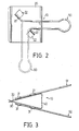
- a conventional clip comprises a main body usually made of a resilient metal sheet while the shank is made of metal strip. As viewed from the side, the main body forms a hollow triangular shape. The two ends of the main body are rolled or folded to produce four hinging slots. The ends of the two shanks are inserted into these hinging slots with the ends of one shank being inserted into the two hinging slot at the upper face and the ends of the other shank being inserted into the other two hinging slots at the lower face.
- the two arms of the shanks are mirror images of each other and are disposed perpendicularly to the clip end. When utilized, these shanks are pressed in such a way that a gap appears between the two clip ends. Paper or documents can then be inserted into the space and clipped once the pressure exerted on the shanks is released.
- the present invention has been arisen from work seeking to mitigate and/or obviate the above-listed drawbacks of the prior art and can be effectively put into practice.
- the present invention is also intended to provide a clip having a pair of shanks capable of being flipped aside.
- a clip 10 constructed in accordance with the present invention comprises a thin resilient metal sheet and a pair of metal shanks.
- the metal sheet is moderately resilient and forms a substantially hollow triangular shape.
- the metal sheet forms an upper face 20 and a lower face 30 as well as a back portion 40.
- the back portion 40 connects the upper face 20 to the lower face 30 while the upper face 20 and lower face 30 contact each other at the ends remote from the back portion 40.
- the clip 10 is further provided with two pairs of hinging slots for receiving the metal shanks.
- a first pair of hinging slots 21 are provided on the upper face 20 and a second pair of hinging slots 31 are provided on the lower face 30.
- the first pair of hinging slots 21 and the second pair of hinging slots 31 respectively defining hinge axes for pivotal movement lying parallel to the respective upper face 20 and lower face 30 set diagonally on the upper face 20 and the lower face 30 relative to the back portion 40 so that one hinging slot of each of the two pairs 21 and 31 is closer to the back portion 40 than the other.
- the upper face 20 is provided with two hinging slots 21.
- These hinging slots 21 are preferably formed by first cutting two areas of roughly rectangular shape at two suitable positions on the face. For each area, one edge remains uncut.
- the cutout area on one side is disposed nearer to the back portion 40 with its uncut edge facing the back portion 40.
- the cutout area on another side is disposed nearer to one of the clip ends with its uncut edge facing the clip end.
- the cutout metal sheet is rolled or folded to form the hinging slots 21 and leaves two holes 22 immediately adjacent to the hinging slots 21.
- the two hinging slots 21 are arranged in such a way that an imaginary line running through the center line of the hinging slots forms a 45 degree angle with the clip end, i.e., the hinging slots 21 are set diagonally on the upper face 20.
- the lower face 30 is provided with two hinging slots 31.
- These hinging slots 31 are preferably formed by first cutting two areas of roughly rectangular shape at two suitable positions on the face. For each area, one edge remains uncut.
- the cutout area on one side is disposed nearer to the back portion 40 with its uncut edge facing the back portion 40.
- the cutout area on another side is disposed nearer to one of the clip ends with its uncut edge facing the clip end.
- the cutout metal sheet is rolled or folded to form the hinging slots 31 and leaves two holes 32 immediately adjacent to the hinging slots 31.
- the two hinging slots 31 are arranged in such a way that an imaginary line running through the center line of the hinging slots forms a 45 degree angle with the clip end, i.e., the hinging slots 31 are set diagonally on the upper face 30.
- the clip 10 includes a pair of metal shanks 50, namely a first shank 51 and a second shank 52.
- first shank 51 is positioned on the upper face 20 and the second shank 52 is positioned on the lower face 30.
- Each of the shanks 51 and 52 has respectively a longer arm and a shorter arm.
- the ends of the longer arms have portions pivotally retained by the hinging slots 21 and 31 adjacent to the edges of the clip structure and the shorter arms also have portions pivotally retained by the hinging slots 21 and 31 adjacent to the back portion 40.
- the shanks 50 is pivotable 90 degrees from an upright position extending beyond the back portion 40 about the axes respectively formed by the first pair of hinging slots 21 and the second pair of hinging slots 31 to a position substantially parallel to the back portion 40.
- the shanks 50 are preferably made of thick gauge metal wire and it should be appreciated that the situation of the lower face 30 is identical to the upper face 20 except that the direction is reversed and a mirror image thereof is observed.
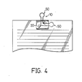
- the shanks 50 in the present improved clip can be flipped aside (refer to FIG. 4).
- the shanks 50 because of their unique diagonal positioning, can be turned 90 degrees from their upright position about the axis of the hinging slots.
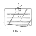
- This is unlike a conventional clip A, wherein the shanks B can only be flipped upward or downward (refer to FIG. 5).
- the unique 'flip aside' feature of the present invention allows the shanks 50 to be conveniently flipped to one side, thereby preventing the problem of shanks protruding out from the file or papers which the clip is holding. Also this 'flip aside' feature allows a clipped paper to be read without unclipping the paper.
Landscapes
- Sheet Holders (AREA)
- Connection Of Plates (AREA)
- Clamps And Clips (AREA)
- Gripping Jigs, Holding Jigs, And Positioning Jigs (AREA)
- Supports Or Holders For Household Use (AREA)
Priority Applications (2)
| Application Number | Priority Date | Filing Date | Title |
|---|---|---|---|
| AT88118511T ATE90275T1 (de) | 1987-01-06 | 1988-11-07 | Federnde klammer. |
| DE8888118511T DE3881696T2 (de) | 1987-01-06 | 1988-11-07 | Federnde klammer. |
Applications Claiming Priority (1)
| Application Number | Priority Date | Filing Date | Title |
|---|---|---|---|
| US07/000,870 US4696081A (en) | 1987-01-06 | 1987-01-06 | Clip resiliant |
Publications (2)
| Publication Number | Publication Date |
|---|---|
| EP0367843A1 true EP0367843A1 (de) | 1990-05-16 |
| EP0367843B1 EP0367843B1 (de) | 1993-06-09 |
Family
ID=21693375
Family Applications (1)
| Application Number | Title | Priority Date | Filing Date |
|---|---|---|---|
| EP88118511A Expired - Lifetime EP0367843B1 (de) | 1987-01-06 | 1988-11-07 | Federnde Klammer |
Country Status (5)
| Country | Link |
|---|---|
| US (1) | US4696081A (de) |
| EP (1) | EP0367843B1 (de) |
| AT (1) | ATE90275T1 (de) |
| DE (1) | DE3881696T2 (de) |
| GB (1) | GB2204348B (de) |
Cited By (5)
| Publication number | Priority date | Publication date | Assignee | Title |
|---|---|---|---|---|
| EP1298269A2 (de) | 2001-09-27 | 2003-04-02 | Gretsch-Unitas GmbH Baubeschläge | Betätigungsgetriebe, insbesondere Schloss für einen Treibstangenbeschlag sowie Treistangenbeschlag mit einem solchen Betätigungsgetriebe |
| CN1317103C (zh) * | 2003-05-06 | 2007-05-23 | 浙江工业大学 | 长尾夹自动装配机 |
| KR100776059B1 (ko) | 2005-06-14 | 2007-11-15 | 김영희 | 사무용 클립 |
| CN102963154A (zh) * | 2012-11-30 | 2013-03-13 | 王汉全 | 双开长尾夹 |
| CN106141681B (zh) * | 2016-09-19 | 2018-04-06 | 瑞安市恒晟自动化设备有限公司 | 铁夹组装机 |
Families Citing this family (21)
| Publication number | Priority date | Publication date | Assignee | Title |
|---|---|---|---|---|
| USD318337S (en) | 1988-12-05 | 1991-07-16 | Taylor Vernon R | Combined portable light and clip |
| USD372498S (en) | 1995-06-13 | 1996-08-06 | Hisao Sato | Paper clip |
| US5533236A (en) * | 1995-08-08 | 1996-07-09 | Chun-Hsiung Hsu | Paper holder |
| JPH10315672A (ja) * | 1997-05-16 | 1998-12-02 | Hisao Sato | 紙葉クリップ |
| US6226840B1 (en) * | 1999-08-05 | 2001-05-08 | Wann-Pao Lu | Structure binder clip |
| US6363941B1 (en) * | 2000-07-05 | 2002-04-02 | Donald R. Combs | Cigar holder |
| US6374463B1 (en) | 2000-10-04 | 2002-04-23 | Kenneth J. Kaufman | Corner clip |
| USD478352S1 (en) | 2002-08-05 | 2003-08-12 | Jin Huang | Paper clip |
| WO2004023976A2 (en) * | 2002-09-13 | 2004-03-25 | Damage Control Surgical Technologies, Inc. | Method and apparatus for vascular and visceral clipping |
| USD526356S1 (en) * | 2004-10-27 | 2006-08-08 | Satoshi Shinya | Paper clip |
| US7120969B2 (en) * | 2004-12-16 | 2006-10-17 | Carls David R | Binder clip |
| GB2443672A (en) * | 2006-05-05 | 2008-05-14 | Richard Brian Wallace | Sun lounger towel clip |
| US8157109B2 (en) * | 2007-12-12 | 2012-04-17 | Deflecto, LLC | Mountable storage apparatus with retractable linking mechanism and method |
| US8769781B2 (en) * | 2010-12-22 | 2014-07-08 | Interdesign, Inc. | Shower caddy clip and sleeve |
| TWM414060U (en) * | 2011-02-23 | 2011-10-11 | Ks Terminals Inc | Clamp structure |
| USD653941S1 (en) * | 2011-03-17 | 2012-02-14 | Precision Perfect Product Development Company | Clip |
| USD653940S1 (en) * | 2011-03-17 | 2012-02-14 | Precision Perfect Product Development Company | Clip |
| JP5215499B1 (ja) * | 2012-10-05 | 2013-06-19 | 等 川上 | ダブルクリップ |
| US9199506B2 (en) * | 2013-06-27 | 2015-12-01 | Stephen Sophorn Lim | Hole-punched binder clip |
| US10231718B2 (en) * | 2014-05-23 | 2019-03-19 | Boston Scientific Scimed, Inc. | Tissue extraction devices and related methods |
| CN112810351A (zh) * | 2021-01-25 | 2021-05-18 | 爱文易成文具有限公司 | 一种省力长尾夹 |
Citations (4)
| Publication number | Priority date | Publication date | Assignee | Title |
|---|---|---|---|---|
| GB344187A (en) * | 1930-02-15 | 1931-03-05 | Thomas Victor White | Improvements in or relating to binder clips |
| US1965554A (en) * | 1933-12-26 | 1934-07-03 | White Cable Ltd | Binder clip |
| GB673029A (en) * | 1950-01-03 | 1952-05-28 | I I Cable Ltd | Improvements in or relating to binder clips |
| US3108304A (en) * | 1960-03-21 | 1963-10-29 | Roy Richard | Cleaning implement having a swivelly mounted handle |
Family Cites Families (4)
| Publication number | Priority date | Publication date | Assignee | Title |
|---|---|---|---|---|
| US1150073A (en) * | 1913-04-21 | 1915-08-17 | Spengler Brothers Company | Binding-clip. |
| GB169310A (en) * | 1920-07-05 | 1921-09-29 | Adolph Myers | Improvements in paper clips |
| GB216393A (en) * | 1923-07-30 | 1924-05-29 | Samuel Henry Crocker | Improvements in letter files |
| US2259505A (en) * | 1940-04-08 | 1941-10-21 | Pollard V Wisdom | Loose-leaf binder clip |
-
1987
- 1987-01-06 US US07/000,870 patent/US4696081A/en not_active Expired - Lifetime
- 1987-05-07 GB GB8710848A patent/GB2204348B/en not_active Expired - Lifetime
-
1988
- 1988-11-07 EP EP88118511A patent/EP0367843B1/de not_active Expired - Lifetime
- 1988-11-07 DE DE8888118511T patent/DE3881696T2/de not_active Expired - Fee Related
- 1988-11-07 AT AT88118511T patent/ATE90275T1/de active
Patent Citations (4)
| Publication number | Priority date | Publication date | Assignee | Title |
|---|---|---|---|---|
| GB344187A (en) * | 1930-02-15 | 1931-03-05 | Thomas Victor White | Improvements in or relating to binder clips |
| US1965554A (en) * | 1933-12-26 | 1934-07-03 | White Cable Ltd | Binder clip |
| GB673029A (en) * | 1950-01-03 | 1952-05-28 | I I Cable Ltd | Improvements in or relating to binder clips |
| US3108304A (en) * | 1960-03-21 | 1963-10-29 | Roy Richard | Cleaning implement having a swivelly mounted handle |
Cited By (5)
| Publication number | Priority date | Publication date | Assignee | Title |
|---|---|---|---|---|
| EP1298269A2 (de) | 2001-09-27 | 2003-04-02 | Gretsch-Unitas GmbH Baubeschläge | Betätigungsgetriebe, insbesondere Schloss für einen Treibstangenbeschlag sowie Treistangenbeschlag mit einem solchen Betätigungsgetriebe |
| CN1317103C (zh) * | 2003-05-06 | 2007-05-23 | 浙江工业大学 | 长尾夹自动装配机 |
| KR100776059B1 (ko) | 2005-06-14 | 2007-11-15 | 김영희 | 사무용 클립 |
| CN102963154A (zh) * | 2012-11-30 | 2013-03-13 | 王汉全 | 双开长尾夹 |
| CN106141681B (zh) * | 2016-09-19 | 2018-04-06 | 瑞安市恒晟自动化设备有限公司 | 铁夹组装机 |
Also Published As
| Publication number | Publication date |
|---|---|
| US4696081A (en) | 1987-09-29 |
| ATE90275T1 (de) | 1993-06-15 |
| DE3881696D1 (de) | 1993-07-15 |
| GB2204348B (en) | 1990-10-03 |
| GB8710848D0 (en) | 1987-06-10 |
| DE3881696T2 (de) | 1993-09-16 |
| EP0367843B1 (de) | 1993-06-09 |
| GB2204348A (en) | 1988-11-09 |
Similar Documents
| Publication | Publication Date | Title |
|---|---|---|
| EP0367843A1 (de) | Federnde Klammer | |
| US5413430A (en) | Clamping device and a clamping file equipped therewith | |
| US5447402A (en) | Instrument for binding papers | |
| DE3873640T2 (de) | Blattausrichtvorrichtung. | |
| JPH0547668Y2 (de) | ||
| US3936202A (en) | Ring binder | |
| JPS6113352Y2 (de) | ||
| US4928361A (en) | Paper clip | |
| US5063640A (en) | Endless filament paper clip | |
| JPH0319071U (de) | ||
| JPH0530943Y2 (de) | ||
| JPS6144856Y2 (de) | ||
| CN2070673U (zh) | 长尾夹 | |
| JPH0434060Y2 (de) | ||
| JP3040867U (ja) | 頁めくり付き積重紙体 | |
| US7121588B1 (en) | Folder with a clamping device | |
| JPH0425351Y2 (de) | ||
| JP3025075U (ja) | 文 鎮 | |
| JPH0616719Y2 (ja) | 書類整理用器具 | |
| JPH0523600Y2 (de) | ||
| JPS5812611A (ja) | 爪切り | |
| JPH0423667Y2 (de) | ||
| JP2998206B2 (ja) | リングとじ具 | |
| JP3624770B2 (ja) | ファイル | |
| JPH0214458Y2 (de) |
Legal Events
| Date | Code | Title | Description |
|---|---|---|---|
| PUAI | Public reference made under article 153(3) epc to a published international application that has entered the european phase |
Free format text: ORIGINAL CODE: 0009012 |
|
| 17P | Request for examination filed |
Effective date: 19881114 |
|
| AK | Designated contracting states |
Kind code of ref document: A1 Designated state(s): AT BE CH DE ES FR GR IT LI LU NL SE |
|
| 17Q | First examination report despatched |
Effective date: 19911113 |
|
| GRAA | (expected) grant |
Free format text: ORIGINAL CODE: 0009210 |
|
| AK | Designated contracting states |
Kind code of ref document: B1 Designated state(s): AT BE CH DE ES FR GR IT LI LU NL SE |
|
| PG25 | Lapsed in a contracting state [announced via postgrant information from national office to epo] |
Ref country code: IT Free format text: LAPSE BECAUSE OF FAILURE TO SUBMIT A TRANSLATION OF THE DESCRIPTION OR TO PAY THE FEE WITHIN THE PRE;WARNING: LAPSES OF ITALIAN PATENTS WITH EFFECTIVE DATE BEFORE 2007 MAY HAVE OCCURRED AT ANY TIME BEFORE 2007. THE CORRECT EFFECTIVE DATE MAY BE DIFFERENT FROM THE ONE RECORDED.SCRIBED TIME-LIMIT Effective date: 19930609 Ref country code: NL Effective date: 19930609 Ref country code: LI Effective date: 19930609 Ref country code: AT Effective date: 19930609 Ref country code: CH Effective date: 19930609 Ref country code: GR Free format text: LAPSE BECAUSE OF FAILURE TO SUBMIT A TRANSLATION OF THE DESCRIPTION OR TO PAY THE FEE WITHIN THE PRESCRIBED TIME-LIMIT Effective date: 19930609 Ref country code: BE Effective date: 19930609 Ref country code: SE Effective date: 19930609 Ref country code: ES Free format text: THE PATENT HAS BEEN ANNULLED BY A DECISION OF A NATIONAL AUTHORITY Effective date: 19930609 |
|
| REF | Corresponds to: |
Ref document number: 90275 Country of ref document: AT Date of ref document: 19930615 Kind code of ref document: T |
|
| REF | Corresponds to: |
Ref document number: 3881696 Country of ref document: DE Date of ref document: 19930715 |
|
| ET | Fr: translation filed | ||
| REG | Reference to a national code |
Ref country code: CH Ref legal event code: PL |
|
| NLV1 | Nl: lapsed or annulled due to failure to fulfill the requirements of art. 29p and 29m of the patents act | ||
| PG25 | Lapsed in a contracting state [announced via postgrant information from national office to epo] |
Ref country code: LU Free format text: LAPSE BECAUSE OF NON-PAYMENT OF DUE FEES Effective date: 19931130 |
|
| PLBE | No opposition filed within time limit |
Free format text: ORIGINAL CODE: 0009261 |
|
| STAA | Information on the status of an ep patent application or granted ep patent |
Free format text: STATUS: NO OPPOSITION FILED WITHIN TIME LIMIT |
|
| 26N | No opposition filed | ||
| PGFP | Annual fee paid to national office [announced via postgrant information from national office to epo] |
Ref country code: DE Payment date: 19961021 Year of fee payment: 9 |
|
| PG25 | Lapsed in a contracting state [announced via postgrant information from national office to epo] |
Ref country code: DE Free format text: LAPSE BECAUSE OF NON-PAYMENT OF DUE FEES Effective date: 19980801 |
|
| PGFP | Annual fee paid to national office [announced via postgrant information from national office to epo] |
Ref country code: FR Payment date: 20041104 Year of fee payment: 17 |
|
| PG25 | Lapsed in a contracting state [announced via postgrant information from national office to epo] |
Ref country code: FR Free format text: LAPSE BECAUSE OF NON-PAYMENT OF DUE FEES Effective date: 20060731 |
|
| REG | Reference to a national code |
Ref country code: FR Ref legal event code: ST Effective date: 20060731 |