EP0367861B1 - Appareil pour le soudage automatique d'angle d'un objet à souder comprenant une plaque de fond et quatre plaques latérales pointées par soudage substantiellement verticalement à ladite plaque de fond - Google Patents
Appareil pour le soudage automatique d'angle d'un objet à souder comprenant une plaque de fond et quatre plaques latérales pointées par soudage substantiellement verticalement à ladite plaque de fond Download PDFInfo
- Publication number
- EP0367861B1 EP0367861B1 EP19880118852 EP88118852A EP0367861B1 EP 0367861 B1 EP0367861 B1 EP 0367861B1 EP 19880118852 EP19880118852 EP 19880118852 EP 88118852 A EP88118852 A EP 88118852A EP 0367861 B1 EP0367861 B1 EP 0367861B1
- Authority
- EP
- European Patent Office
- Prior art keywords
- carriage
- welding
- bottom plate
- welded
- weld line
- Prior art date
- Legal status (The legal status is an assumption and is not a legal conclusion. Google has not performed a legal analysis and makes no representation as to the accuracy of the status listed.)
- Expired - Lifetime
Links
Images


Classifications
-
- B—PERFORMING OPERATIONS; TRANSPORTING
- B23—MACHINE TOOLS; METAL-WORKING NOT OTHERWISE PROVIDED FOR
- B23K—SOLDERING OR UNSOLDERING; WELDING; CLADDING OR PLATING BY SOLDERING OR WELDING; CUTTING BY APPLYING HEAT LOCALLY, e.g. FLAME CUTTING; WORKING BY LASER BEAM
- B23K9/00—Arc welding or cutting
- B23K9/12—Automatic feeding or moving of electrodes or work for spot or seam welding or cutting
-
- B—PERFORMING OPERATIONS; TRANSPORTING
- B23—MACHINE TOOLS; METAL-WORKING NOT OTHERWISE PROVIDED FOR
- B23K—SOLDERING OR UNSOLDERING; WELDING; CLADDING OR PLATING BY SOLDERING OR WELDING; CUTTING BY APPLYING HEAT LOCALLY, e.g. FLAME CUTTING; WORKING BY LASER BEAM
- B23K37/00—Auxiliary devices or processes, not specially adapted for a procedure covered by only one of the other main groups of this subclass
- B23K37/02—Carriages for supporting the welding or cutting element
- B23K37/0264—Carriages for supporting the welding or cutting element magnetically attached to the workpiece
-
- B—PERFORMING OPERATIONS; TRANSPORTING
- B23—MACHINE TOOLS; METAL-WORKING NOT OTHERWISE PROVIDED FOR
- B23K—SOLDERING OR UNSOLDERING; WELDING; CLADDING OR PLATING BY SOLDERING OR WELDING; CUTTING BY APPLYING HEAT LOCALLY, e.g. FLAME CUTTING; WORKING BY LASER BEAM
- B23K9/00—Arc welding or cutting
- B23K9/02—Seam welding; Backing means; Inserts
-
- B—PERFORMING OPERATIONS; TRANSPORTING
- B23—MACHINE TOOLS; METAL-WORKING NOT OTHERWISE PROVIDED FOR
- B23K—SOLDERING OR UNSOLDERING; WELDING; CLADDING OR PLATING BY SOLDERING OR WELDING; CUTTING BY APPLYING HEAT LOCALLY, e.g. FLAME CUTTING; WORKING BY LASER BEAM
- B23K9/00—Arc welding or cutting
- B23K9/24—Features related to electrodes
- B23K9/28—Supporting devices for electrodes
- B23K9/287—Supporting devices for electrode holders
Definitions
- the present invention relates to an apparatus for automatically fillet-welding an object to be welded comprising a rectangular bottom plate and four side plates tack-welded substantially vertically to the bottom plate, along a weld line formed thereon.
- the above-mentioned conventional welding method has however the following problems. Since the weld line is fillet-welded by automatic welding and manual welding, the weld bead height cannot be kept constant, thus tending to cause unstable quality of the fillet-welded joint and a low welding efficiency.
- US-A-4,704,513 discloses a groove tracing control method for a fillet welding effected by rotating a welding torch and thereby rotating an arc at a high speed.
- This prior art groove tracing control of the welding torch is effected in accordance with variations in the voltage waveform of the rotating arc and in this way the groove tracing is effected in real time in a noncontact manner with a high degree of accuracy.
- US-A-3,777,834 discloses a magnet vehicle supportedly adhered to and adapted to run over an inclined wall surface of a structural member made of a strong magnetic material such as iron and steel. Said vehicle can be altered of its direction of travel as desired on said surface.
- EP-A1-0 367 850 which falls under Article 54,3 EPC discloses an apparatus for automatically fillet-welding an object to be welded comprising a rectangular plate and four side plates tack-welded substantially vertically to said bottom plate.
- An object of the present invention is therefore to provide a welding apparatus which permits automatic fillet-welding at a high efficiency of an object to be welded comprising a rectangular bottom plate and four side plates tack-welded substantially vertically to the bottom plate, along a weld line formed thereon, and maintenance of a constant weld bead height, thus allowing stabilization of quality of a fillet-welded joint.
- an apparatus for automatically fillet-welding an object to be welded comprising a rectangular bottom plate and four side plates tack-welded substantially vertically to said bottom plate, comprising the features of claim 1.
- a welding head comprising a welding nozzle for guiding a welding wire toward a weld line, an X-axis profiling mechanism for horizontally moving the welding nozzle, and a Y-axis profiling mechanism for vertically moving the welding nozzle; providing at least one carriage front sensor on the front side of the carriage relative to the travelling direction of the carriage and two carriage rear sensors on the rear side of the carriage relative to the travelling direction of the carriage; and controlling the X-axis profiling mechanism, the Y-axis profiling mechanism and a carriage travelling motor by means of a welding controller.
- Fig. 1 is a schematic plan view illustrating an embodiment of the fillet-welding apparatus of the present invention
- Fig. 2 is a schematic side view illustrating the fillet-welding apparatus of the present invention shown in Fig. 1
- Fig. 3 is a schematic side view illustrating the rod and the rod lift mechanism in the fillet-welding apparatus of the present invention
- Fig. 4 is a schematic bottom view illustrating the fillet-welding apparatus of the present invention
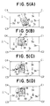
- Figs. 5(A) to 5(I) are schematic descriptive plan views illustrating function of the fillet-welding apparatus of the present invention
- Fig. 6 is a block diagram illustrating control of the fillet-welding apparatus of the present invention by means of the welding controller.
- the apparatus of the present invention for automatically fillet-welding an object to be welded 1 comprising a rectangular bottom plate 2 and four side plates 3 tack-welded substantially vertically to the bottom plate 2, along a weld line 4 formed on the object to be welded 1, comprises: a carriage 5 travellable on the bottom plate 2 of the object to be welded 1 in parallel with the four side plates 3 thereof and capable of changing the direction; a rod 9 having an electromagnet 10 at the lower end thereof, vertically passing through the carriage 5 at the center thereof and vertically movable; a rod lift mechanism 11 provided on the carriage 5; a welding head 12 mounted on the carriage 5; a carriage direction change angle detecting mechanism 17 provided on the carriage 5; a carriage position detecting mechanism comprising at least one carriage front sensor 18 provided on the front side of the carriage 5 relative to the travelling direction thereof, and two carriage rear sensors 19, 19' provided on the rear side of the carriage 5 relative to the travelling direction thereof; and
- the carriage 5 has a pair of wheels 7, 7' each having an independent carriage travelling motor 6, 6', provided on two opposing sides of the carriage 5, and a pair of casters 8, 8' provided on the other opposing sides of the carriage 5.
- the carriage 5 travels forward or back by positively or negatively driving both the carriage travelling motors 6, 6'.
- the carriage 5 changes the direction thereof by positively driving one of the carriage travelling motors 6, 6' and negatively driving the other one thereof.
- the rod 9 descends onto the bottom plate 2 of the object to be welded 1 when the carriage 5 changes the direction thereof to serve as the center axle for the change in direction of the carriage 5 through adhesion of the electromagnet 10 to the bottom plate 2.
- the rod lift mechanism 11 comprises for example a solenoid. By magnetically exciting the solenoid, the rod 9 moves upward, and by releasing magnetical excitation of the solenoid, the rod 9 descends onto the bottom plate 2.
- the welding head 12 comprises a welding nozzle 13 for guiding a welding wire 14 toward the weld line 4 formed between the bottom plate 2 and the side plates 3 of the object to be welded 1, an X-axis profiling mechanism 15 for moving the welding nozzle 13 horizontally and at right angles to the weld line 4 so that the extension of the center axis of the welding nozzle 13 intersects the weld line 4, and a Y-axis profiling mechanism 16 for moving the welding nozzle 13 along the center axis thereof so that a gap between the tip of the welding wire 14 and the weld line 4 is kept at a prescribed constant distance.
- the welding nozzle 13 rotates at a high speed in a certain direction around the center axis thereof.
- the welding wire 14 is fed through the welding nozzle 13 toward the weld line 4, eccentrically from the center axis of the welding nozzle 13.
- 21 is a shielding gas feeding nozzle provided concentrically on the outside of the welding nozzle 13.
- the shielding gas feeding nozzle 21 is secured to the welding head 12.
- Welding current is supplied between the welding wire 14 and the object to be welded 1 from a welding electric power source not shown, whereby an arc is produced between the tip of the welding wire 14 and the object to be welded 1.
- the thus produced arc acts a circular motion corresponding to the above-mentioned eccentricity of the welding wire 14 along with the rotation of the welding nozzle 13.
- the bottom plate 2 and the side plates 3 are fillet-welded together by the heat of the thus produced arc along the weld line 4 formed thereon.
- the arc and a molten pool are shielded from the open air by a shielding gas ejected from the shielding gas feeding nozzle 21.
- the X-axis profiling mechanism 15 comprises, for example, a rack and pinion mechanism (not shown), and moves the welding nozzle 13, together with the Y-axis profiling mechanism 16, horizontally and at right angles to the weld line 4 as described above, in the X-axis direction shown by an arrow in Fig. 2.
- the Y-axis profiling mechanism 16 also comprises, for example, a rack and pinion mechanism (not shown), and moves the welding nozzle 13 along the center axis thereof as described above, in the Y-axis direction shown by an arrow in Fig. 2.
- the carriage direction change angle detecting mechanism 17 comprises, for example, an encoder, and detects a direction change angle of the carriage 5 from a home position thereof.
- the carriage position detecting mechanism comprises at least one carriage front sensor 18, provided on the front side of the carriage 5 relative to the travelling direction thereof, for detecting a distance from the front side of the carriage 5 to the side plate 3 perpendicular to the travelling direction of the carriage 5, and two carriage rear sensors 19, 19', provided on the rear side of the carriage 5 relative to the travelling direction thereof, for detecting a distance from the rear side of the carriage 5 to the side plate 3 perpendicular to the travelling direction of the carriage 5.
- the carriage front sensor 18 comprises, for example, a photosensor
- the carriage rear sensors 19, 19' comprise, for example, limit switches.
- the welding controller 20 shown in Fig. 6 comprises an X-axis profiling controller, a Y-axis profiling controller, a carriage travel controller, a rod lift controller and a welding completion controller.
- the X-axis profiling controller controls the X-axis profiling mechanism 15 in response to any one of voltage and current of the welding current so that the extension of the center axis of the welding nozzle 13 intersects the weld line 4. Control of the X-axis profiling mechanism 15 by means of the X-axis profiling controller is described below further in detail.
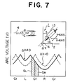
- Fig. 7 shows the waveform of voltage of the welding current, i.e., the waveform of arc voltage for each rotation of the welding nozzle 13.
- points “Cf", “Cr”, “L” and “R” show positions of the welding wire 14 (i.e., the arc) during one rotation thereof, as viewed in a plan, in the weld line 4 of the object to be welded 1. More particularly, point “Cf" represents the downstream position in the welding direction, point “Cr", the upstream position in the welding direction, and points "L” and “R”, the both side positions in the welding direction.
- arc voltage shows the highest value at points "Cf" and "Cr” where the distance between the tip of the welding wire 14 and the object to be welded 1 is the longest.
- arc voltage shows the lowest value at points "L” and "R” where the distance between the tip of the welding wire 14 and the object to be welded 1 is the shortest.
- Arc voltage has a waveform symmetrical relative to point "Cf" or "Cr".
- the solid line represents the waveform of arc voltage in the case where the extension of the center axis of the welding nozzle 13 does not intersect the weld line 4, and deviates from the weld line 4 toward the side plate 3, i.e., in the case of ⁇ X ⁇ 0.
- arc voltage has a waveform asymmetrical relative to point "Cf" or "Cr".
- each of the above-mentioned phase angle from point “Cf" toward point “L” and the phase angle from point “Cf” toward point “R” should preferably be up to 90°. With a value of the phase angle of over 90°, the waveform of arc voltage is distorted under the effect of the molten pool present in the upstream in the welding direction, and this may make it impossible to conduct accurate control of the X-axis profiling mechanism 15 by means of the X-axis profiling controller.
- the above-mentioned control can also be accomplished with the use of the welding current instead of arc voltage described above.
- the Y-axis profiling controller controls the Y-axis profiling mechanism 16 to move the welding nozzle 13 along the center axis thereof in response to any one of voltage and current of the welding current so that the gap between the tip of the welding wire 14 and the weld line 4 is kept at a prescribed constant distance.
- the carriage travel controller controls the carriage travelling motors 6, 6' in response to signals from the carriage front sensor 18, the carriage rear sensors 19, 19' and the carriage direction change angle detecting mechanism 17 so as to cause the carriage 5 to travel, stop or change the direction thereof.
- the carriage travel controller further controls the carriage travelling motors 6, 6' in response to a signal from the carriage direction change angle detecting mechanism 17 upon direction change of the carriage 5 so as to adjust a carriage direction changing speed. Control of the carriage travelling motors 6, 6' by means of the carriage travel controller upon direction change of the carriage is described below further in detail. Fig.
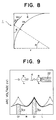
- FIG. 8 shows the relationship between a swing radius of the welding nozzle 13 and a welding speed when welding a corner portion of the object to be welded 1 along the weld line 4 by means of the welding nozzle 13 swinging along with the direction change of the carriage 5.
- ⁇ is a swing angle of the welding nozzle 13
- r is a standard swing radius of the welding nozzle 13 upon start of swinging.
- the carriage travel controller controls the carriage travelling motors 6, 6' in response to a signal from the carriage direction change angle detecting mechanism 17, i.e., the swing angle " ⁇ " of the welding nozzle 13 in accordance with the above-mentioned formulae (3) and (4).
- the welding speed "V W " along the weld line 4 upon swinging of the welding nozzle 13 is kept at a prescribed constant value.
- the rod lift controller controls the rod lift mechanism 11 in response to signals from the carriage front sensor 18 and the carriage direction change angle detecting mechanism 17 so as to vertically move the rod 9.
- the welding completion controller controls the carriage travelling motors 6, 6' and a welding electric power source not shown in response to any one of voltage and current of the welding current so as to determine the completion of welding, cause the carriage 5 to stop travelling, and cause the welding electric power source to discontinue supply of the welding current. Control of the carriage travelling motors 6, 6' and the welding electric power source by means of the welding completion controller is described below further in detail.
- Fig. 9 shows the waveform of voltage of the welding current, i.e., the waveform of arc voltage for each rotation of the welding nozzle 13 in the close vicinity of the welding completion position. In Fig.
- points “Cf”, “Cr”, “L” and “R” show positions of the welding wire 14 (i.e., the arc) during one rotation thereof, as viewed in a plan, in the weld line 4 of the object to be welded 1. More particularly, point “Cf” represents the downstream position in the welding direction, point “Cr” the upstream position in the welding direction, and points “L” and “R”, the both side positions in the welding direction, as has been described with regard to Fig. 7. In Fig. 9, 22 represents a weld bead formed in the initial welding.
- arc voltage shows the highest value at points "Cf" and “Cr”, and shows the lowest value at points "L” and "R".
- the solid line represents the waveform of arc voltage when welding is carried out at a position where point "Cf" the welding wire 14 has reached the weld bead 22 formed in the initial welding, and point “Cr” of the welding wire 14 has not yet reached on the weld bead 22.
- arc voltage at point "Cf" of the welding wire 14, which has reached the weld bead 22 is lower than arc voltage at point "Cr" of the welding wire 14, which has not yet reached the weld bead 22.
- the welding completion controller controls the carriage travelling motors 6, 6' and the welding electric power source not shown so as to cause the carriage 5 to stop travelling and cause the welding electric power source to discontinue supply of the welding current. It is thus possible to automatically terminate welding at a position where the weld bead 22 formed in the initial welding exists.
- the above-mentioned control can be accomplished with the use of the welding current instead of arc voltage
- an embodiment is described below with reference to Figs.
- an object to be welded 1 comprising a rectangular bottom plate 2 and four side plates 3a, 3b, 3c and 3d tack-welded substantially vertically to the bottom plate 2 and having corners C1, C2, C3 and C4 is automatically fillet-welded along a weld line formed thereon, with the use of the fillet-welding apparatus of the present invention described above.
- the carriage 5 is placed on the bottom plate 2 at an arbitrary position on the bottom plate 2. Then, the carriage travelling motors 6, 6' are driven to move the carriage 5 toward the side plate 3a facing the two carriage rear sensors 19, 19', in the direction indicated by an arrow so as to bring both of the two carriage rear sensors 19, 19' into contact with the side plate 3a.
- the carriage 5 is positioned at right angles to the side plate 3a relative to the travel direction of the carriage. Then, the carriage travelling motors 6, 6' are driven to move the carriage 5 by a prescribed distance toward the side plate 3c facing the at least one carriage front sensor 18. Then, as shown by an arrow in Fig.
- the carriage 5 is caused to change the direction thereof anticlockwise by 180° so that the carriage front sensor 18 faces the side plate 3a and the carriage rear sensors 19, 19' face the side plate 3c. Subsequently, the distance between the front of the carriage 5 and the side plate 3a is detected by the carriage front sensor 18. Then, as shown in Fig. 5(D), the carriage 5 is moved to a position where the gap between the tip of the welding wire 14 and the weld line becomes a prescribed distance when the welding nozzle 13 faces the side plate 3a as a result of the direction change of the carriage 5. Then, as shown by an arrow in Fig. 5(D), the carriage 5 is caused to change the direction thereof clockwise by 90° so that the welding nozzle 13 faces the side plate 3a.
- the carriage is positioned at a welding starting point where the welding nozzle 13 is directed toward the side plate 3a.
- the carriage 5 changes the direction thereof as described above, the rod 9 descends onto the bottom plate 2 and the electromagnet 10 at the lower end of the rod 9 is magnetically excited and adheres to the bottom plate 2, whereby the rod 9 serves as the center axle for the direction change.
- the carriage 5 positioned at the welding starting point as described above travels as shown by an arrow in Fig. 5(E) toward the side plate 3b in parallel with the side plate 3a through driving of the carriage travelling motors 6, 6'.
- the bottom plate 2 and the side plate 3a are fillet-welded together along the weld line formed thereon as shown in Fig. 5(F), by means of the welding nozzle 13 rotating at a high speed around the center axis thereof.
- the welding nozzle 13 is controlled by the X-axis profiling mechanism 15 and the X-axis profiling controller so that the extension of the center axis of the welding nozzle 13 intersects the weld line, and further, the welding nozzle 13 is controlled by the Y-axis profiling mechanism 16 and the Y-axis profiling controller so that the gap between the tip of the welding wire 14 and the weld line is kept at a prescribed constant distance.
- the carriage travelling motors 6, 6' control the respective revolutions of the wheels 7, 7' of the carriage 5 so that the carriage 5 laterally moves so as to bring the welding nozzle 13 back to the standard position thereof.
- the carriage 5 travels in parallel with the side plate 3a while keeping the gap between the carriage 5 and the side plate 3a at a prescribed constant distance.
- the carriage front sensor 18, which is provided on the front side of the carriage 5, detects the distance from the front side of the carriage 5 to the side plate 3b perpendicular to the travelling direction of the carriage 5.
- the carriage travelling motors 6, 6' are controlled by means of the carriage travel controller in response to a signal from the carriage front sensor 18, which indicates that the carriage 5 has reached the position at a prescribed distance from the side plate 3b, and the carriage 5 stops as shown in Fig. 5(F).
- the above-mentioned prescribed distance is predetermined on the basis of the swing radius of the welding nozzle 13 caused by the direction change of the carriage 5 and the distance of horizontal movement of the welding nozzle 13 by means of the X-axis profiling mechanism 15, and is entered in advance into the carriage travel controller.
- Control of the direction changing speed of the carriage 5 is accomplished by detecting the direction change angle of the carriage 5 from the home position thereof by means of the carriage direction change angle detecting mechanism 17, and controlling the carriage travelling motors 6, 6' by means of the carriage travel controller in response to the thus detected direction change angle of the carriage 5.
- the welding nozzle 13 swings horizontally by 90°, and as shown in Figs. 5(G) and 5(H), the corner C1 and the proximity thereof are fillet-welded together at a prescribed constant welding speed along the weld line.
- Fig. 10 is a block diagram illustrating the steps for fillet-welding of the corner portion as described above by means of the fillet-welding apparatus of the present invention.
- the carriage 5 is caused to travel, by driving of the carriage travelling motors 6, 6', in parallel with the side plate 3b toward the side plate 3c.
- the bottom plate 2 and the side plate 3b are fillet-welded together by means of the welding nozzle 13 along the weld line formed thereon as shown in Fig. 5(I).
- the carriage front sensor 18, which is provided on the front side of the carriage 5, detects the distance from the front side of the carriage 5 to the side plate 3c perpendicular to the travelling direction of the carriage 5.
- the carriage travelling motors 6, 6' are controlled by means of the carriage travel controller in response to a signal from the carriage front sensor 18, which indicates that the carriage 5 has reached the position at a prescribed distance from the side plate 3c, and the carriage 5 stops as shown in Fig. 5(I). Subsequently, as described above, the rod 9 is caused to descend onto the bottom plate 2 by means of the rod lift mechanism 11, and the electromagnet 10 at the lower end of the rod 9 adheres to the bottom plate 2. Then, as a result of driving of the carriage travelling motors 6, 6', the carriage 5 changes the direction thereof by 90° as shown by an arrow in Fig. 5(I) with the rod 9 as the center axle, while the direction chaning speed thereof is controlled. As the carriage 5 changes the direction thereof, the welding nozzle 13 swings horizontally by 90°, and the corner C2 and the proximity thereof are fillet-welded together at a prescribed constant welding speed along the weld line.
- the carriage 5 travels in parallel with the side plate 3c toward the side plate 3d, stops at the position at a prescribed distance from the side plate 3d, and then changes the direction thereof by 90°.
- the bottom plate 2 and the side plate 3c, and the corner portion C3 are fillet-welded together along the weld line formed thereon.
- the carriage 5 travels in parallel with the side plate 3d toward the side plate 3a, stops at the position at a prescribed distance from the side plate 3a, and then changes the direction thereof by 90°.
- the bottom plate 2 and the side plate 3d, and the corner portion C4 are fillet-welded together along the weld line formed thereon.
- Carriage 5 travels again in parallel with the side plate 3a toward the side plate 3b, and the portion not as yet welded between the bottom plate 2 and the side plate 3a is fillet-welded along the weld line formed thereon.
- the welding completion controller determines the completion of welding as described above.
- the welding completion controller controls the carriage travelling motors 6, 6' and the welding electric power source not shown so as to cause the carriage 5 to stop travelling and to cause the welding electric power source to discontinue supply of the welding current.
- the object to be welded 1 comprising the rectangular bottom plate 2 and the four side plates 3a, 3b, 3c and 3d tack-welded substantially vertically to the bottom plate 2 and having the four corners C1, C2, C3 and C4 is automatically fillet-welded along the weld line formed thereon.
- the fillet-welding apparatus of the present invention as described above in detail, it is possible to automatically fillet-weld at a high efficiency an object to be welded comprising a rectangular bottom plate and four side plates tack-welded substantially vertically to the bottom plate, along a weld line formed thereon, while keeping a constant weld bead height and a stable quality of a fillet-welded joint, thus providing industrially useful effects.
Landscapes
- Engineering & Computer Science (AREA)
- Physics & Mathematics (AREA)
- Mechanical Engineering (AREA)
- Plasma & Fusion (AREA)
- Optics & Photonics (AREA)
- Butt Welding And Welding Of Specific Article (AREA)
Claims (1)
- Appareil de soudage automatique d'angle d'un objet à souder comprenant une plaque inférieure rectangulaire et quatre plaques latérales, soudées localement afin qu'elles soient sensiblement perpendiculaires à la plaque inférieure, l'appareil comprenant :
un chariot (5) destiné à se déplacer sur la plaque inférieure parallèlement aux quatre plaques latérales, le chariot ayant une paire de roues (7, 7') ayant chacune un moteur indépendant (6, 6') de déplacement de chariot, les roues étant placées de deux côtés opposés du chariot (5), et deux roulettes (8, 8') placées sur les deux autres côtés opposés du chariot (5) et permettant ainsi un déplacement et un changement de direction du chariot (5) à l'aide de la paire de roues (7, 7') et de la paire de roulettes (8, 8'),
une tige (9) ayant un électro-aimant (10) à son extrémité inférieure, passant verticalement à travers le chariot (5) au centre de celui-ci et mobile verticalement, la tige descendant sur la plaque inférieure de l'objet à souder lorsque le chariot (5) change de direction pour être utilisée comme axe central du changement de direction par adhérence de l'électro-aimant (10) à la plaque inférieure,
un mécanisme (11) de soulèvement de tige, placé sur le chariot (5) et destiné à déplacer verticalement la tige (9),
une tête (12) de soudage montée sur le chariot (5), la tête de soudage comportant une buse de soudage (13), tournant autour de son axe central, destinée à guider un fil de soudage (14) vers une ligne de soudage de l'objet à souder, un mécanisme (15) de profilage d'axe X destiné à déplacer la buse de soudage (13) horizontalement et perpendiculairement à la ligne de soudage afin que le prolongement de l'axe central de la buse de soudage (13) recoupe la ligne de soudage, et un mécanisme (16) de profilage d'axe Y destiné à déplacer la buse de soudage (13) le long de son axe central afin que la distance comprise entre le bout du fil de soudage (14) et la ligne de soudage garde une dimension constante prescrite,
un mécanisme (17) de détection d'angle de changement de direction de chariot, disposé sur le chariot (5) et destiné à détecter un angle de changement de direction du chariot (5) par rapport à une position de repos,
un mécanisme de détection de position de chariot, ce mécanisme comprenant au moins un capteur avant (18) de chariot, placé du côté avant du chariot (5) dans la direction de déplacement de celui-ci et destiné à détecter la distance comprise entre la face avant du chariot (5) et la plaque latérale perpendiculaire à la direction de déplacement du chariot (5), et deux capteurs arrière (19, 19') de chariot, placés à l'arrière du chariot (5) par rapport à la direction de déplacement de celui-ci et destinés à détecter la distance comprise entre le côté arrière du chariot (5) et la plaque latérale perpendiculaire à la direction de déplacement du chariot (5), et
un organe (20) de commande de soudage qui comporte un organe de commande de profilage d'axe X destiné à commander le mécanisme (15) de profilage d'axe X en fonction de la tension ou de l'intensité d'un courant de soudage afin que le prolongement de l'axe central de la buse de soudage (13) recoupe la ligne de soudage, un organe de commande de profilage d'axe Y destiné à commander le mécanisme (16) de profilage d'axe Y en fonction de la tension ou de l'intensité du courant de soudage afin qu'un espace compris entre le bout du fil de soudage (14) et la ligne de soudage garde une dimension constante prescrite, un organe de commande de déplacement de chariot destiné à commander les moteurs (6, 6') de déplacement de chariot en fonction de signaux provenant du mécanisme (18, 19, 19') de détection de position de chariot et du mécanisme (17) de détection d'angle de changement de direction de chariot afin que le chariot (5) se déplace, s'arrête ou change de direction, un organe de commande de soulèvement de tige destiné à commander le mécanisme (11) de soulèvement de tige en fonction de signaux provenant d'au moins un capteur avant (18) de chariot et du mécanisme (17) de détection d'angle de changement de direction de chariot afin que la tige (9) soit déplacée verticalement, et un organe de commande de fin de soudage destiné à commander les moteurs (6, 6') de déplacement de chariot et une alimentation électrique de soudage en fonction de la tension ou de l'intensité du courant de soudage afin que la fin du soudage soit déterminée, que le chariot (5) cesse de se déplacer, et que l'alimentation électrique de soudage cesse de transmettre le courant de soudage.
Priority Applications (2)
| Application Number | Priority Date | Filing Date | Title |
|---|---|---|---|
| EP19880118852 EP0367861B1 (fr) | 1988-11-11 | 1988-11-11 | Appareil pour le soudage automatique d'angle d'un objet à souder comprenant une plaque de fond et quatre plaques latérales pointées par soudage substantiellement verticalement à ladite plaque de fond |
| DE19883879495 DE3879495T2 (de) | 1988-11-11 | 1988-11-11 | Geraet zum selbsttaetigen kehlnahtschweissen eines schweissgegenstandes, bestehend aus einer viereckigen bodenplatte und vier wesentlich lotrecht zur erwaehnten bodenplatte zusammengehefteten seitenplatten. |
Applications Claiming Priority (1)
| Application Number | Priority Date | Filing Date | Title |
|---|---|---|---|
| EP19880118852 EP0367861B1 (fr) | 1988-11-11 | 1988-11-11 | Appareil pour le soudage automatique d'angle d'un objet à souder comprenant une plaque de fond et quatre plaques latérales pointées par soudage substantiellement verticalement à ladite plaque de fond |
Publications (2)
| Publication Number | Publication Date |
|---|---|
| EP0367861A1 EP0367861A1 (fr) | 1990-05-16 |
| EP0367861B1 true EP0367861B1 (fr) | 1993-03-17 |
Family
ID=8199551
Family Applications (1)
| Application Number | Title | Priority Date | Filing Date |
|---|---|---|---|
| EP19880118852 Expired - Lifetime EP0367861B1 (fr) | 1988-11-11 | 1988-11-11 | Appareil pour le soudage automatique d'angle d'un objet à souder comprenant une plaque de fond et quatre plaques latérales pointées par soudage substantiellement verticalement à ladite plaque de fond |
Country Status (2)
| Country | Link |
|---|---|
| EP (1) | EP0367861B1 (fr) |
| DE (1) | DE3879495T2 (fr) |
Families Citing this family (4)
| Publication number | Priority date | Publication date | Assignee | Title |
|---|---|---|---|---|
| EP0771612B1 (fr) * | 1991-08-27 | 2002-03-06 | Mitsubishi Jukogyo Kabushiki Kaisha | Appareil à jet de surface de sol |
| US7896216B2 (en) | 2007-03-30 | 2011-03-01 | Kawasaki Jukogyo Kabushiki Kaisha | Sticking pad, friction stir welding machine and friction stir welding system |
| DE202008005421U1 (de) * | 2008-04-14 | 2009-08-27 | Robotics Technology Leaders Gmbh | Robotiksystem |
| US10828660B2 (en) * | 2016-07-27 | 2020-11-10 | Newpark Mats & Integrated Services Llc | Methods for reinforcing a multi-panel support mat |
Family Cites Families (3)
| Publication number | Priority date | Publication date | Assignee | Title |
|---|---|---|---|---|
| GB1286203A (en) * | 1969-05-16 | 1972-08-23 | Hitachi Metals Ltd | Vehicle |
| DD224256A1 (de) * | 1984-04-13 | 1985-07-03 | Schiffbau Veb K | Selbsttaetige positionieranordnung fuer schweissgeraete |
| KR900003972B1 (ko) * | 1985-04-30 | 1990-06-07 | 닛뽕 고오깡 가부시기가이샤 | 고속회전 아아크 필릿(fillet)용접의 그루우브 트레이싱(GROOVE TRACING) 제어방법 |
-
1988
- 1988-11-11 EP EP19880118852 patent/EP0367861B1/fr not_active Expired - Lifetime
- 1988-11-11 DE DE19883879495 patent/DE3879495T2/de not_active Expired - Fee Related
Also Published As
| Publication number | Publication date |
|---|---|
| DE3879495T2 (de) | 1993-06-24 |
| EP0367861A1 (fr) | 1990-05-16 |
| DE3879495D1 (de) | 1993-04-22 |
Similar Documents
| Publication | Publication Date | Title |
|---|---|---|
| US3646309A (en) | Self-adaptive welding torch controller | |
| EP0066626B1 (fr) | Procede de soudage a l'arc rotatif | |
| US3989921A (en) | Method and apparatus for non-consumable electrode type automatic arc welding | |
| EP0367861B1 (fr) | Appareil pour le soudage automatique d'angle d'un objet à souder comprenant une plaque de fond et quatre plaques latérales pointées par soudage substantiellement verticalement à ladite plaque de fond | |
| EP0677353B1 (fr) | Robot de soudage en treillis et procédé du soudage en treillis | |
| EP0367850B1 (fr) | Appareil pour le soudage automatique d'angle d'un objet à souder comprenant une plaque de fond et quatre plaques latérales pointées par soudage substantiellement vertical à la dite plaque de fond | |
| JPH0390283A (ja) | 片面自動溶接の裏面開先情報検出方法 | |
| JPS58205680A (ja) | ア−ク溶接の倣い制御方法 | |
| JPS58205679A (ja) | ア−ク溶接におけるア−ク柱の偏向方法およびその装置 | |
| JP2857309B2 (ja) | 非消耗電極式自動アーク溶接方法 | |
| JPH0390282A (ja) | 片面自動溶接の開先情報検出方法 | |
| EP0093811B1 (fr) | Méthode automatique de soudage à l'arc | |
| JP2003181644A (ja) | X開先継手の多層盛溶接方法 | |
| JPH0683898B2 (ja) | 自走式溶接ロボツト | |
| US4417128A (en) | Arc welding method utilizing reciprocal movement of a torch in width direction of groove to be welded, and continuous movement of torch in longitudinal direction of groove to be welded | |
| JPS6317553B2 (fr) | ||
| JP2000317632A (ja) | 溶接線倣い装置 | |
| JPH0459992B2 (fr) | ||
| SU1201085A1 (ru) | Автомат дл сварки под флюсом горизонтальных стыков на вертикальной плоскости | |
| JPS5948702B2 (ja) | 消耗電極式横向自動溶接法および装置 | |
| JPH0722830B2 (ja) | 自動溶接機におけるトーチの位置制御方法 | |
| EP0085215B1 (fr) | Méthode de soudage à l'arc | |
| JPH0577051A (ja) | プラズマガウジング装置 | |
| JPH06297147A (ja) | 自動溶接装置 | |
| JPH06312268A (ja) | プラズマトーチの高さ制御方法及び高さ制御装置 |
Legal Events
| Date | Code | Title | Description |
|---|---|---|---|
| PUAI | Public reference made under article 153(3) epc to a published international application that has entered the european phase |
Free format text: ORIGINAL CODE: 0009012 |
|
| 17P | Request for examination filed |
Effective date: 19881208 |
|
| AK | Designated contracting states |
Kind code of ref document: A1 Designated state(s): DE FR GB IT SE |
|
| 17Q | First examination report despatched |
Effective date: 19911030 |
|
| GRAA | (expected) grant |
Free format text: ORIGINAL CODE: 0009210 |
|
| AK | Designated contracting states |
Kind code of ref document: B1 Designated state(s): DE FR GB IT SE |
|
| ITF | It: translation for a ep patent filed | ||
| REF | Corresponds to: |
Ref document number: 3879495 Country of ref document: DE Date of ref document: 19930422 |
|
| ET | Fr: translation filed | ||
| PG25 | Lapsed in a contracting state [announced via postgrant information from national office to epo] |
Ref country code: GB Effective date: 19931111 |
|
| PLBE | No opposition filed within time limit |
Free format text: ORIGINAL CODE: 0009261 |
|
| STAA | Information on the status of an ep patent application or granted ep patent |
Free format text: STATUS: NO OPPOSITION FILED WITHIN TIME LIMIT |
|
| 26N | No opposition filed | ||
| GBPC | Gb: european patent ceased through non-payment of renewal fee |
Effective date: 19931111 |
|
| PG25 | Lapsed in a contracting state [announced via postgrant information from national office to epo] |
Ref country code: FR Effective date: 19940729 |
|
| PG25 | Lapsed in a contracting state [announced via postgrant information from national office to epo] |
Ref country code: DE Effective date: 19940802 |
|
| REG | Reference to a national code |
Ref country code: FR Ref legal event code: ST |
|
| EAL | Se: european patent in force in sweden |
Ref document number: 88118852.8 |
|
| PGFP | Annual fee paid to national office [announced via postgrant information from national office to epo] |
Ref country code: SE Payment date: 19981105 Year of fee payment: 11 |
|
| PG25 | Lapsed in a contracting state [announced via postgrant information from national office to epo] |
Ref country code: SE Free format text: LAPSE BECAUSE OF NON-PAYMENT OF DUE FEES Effective date: 19991112 |
|
| EUG | Se: european patent has lapsed |
Ref document number: 88118852.8 |
|
| PG25 | Lapsed in a contracting state [announced via postgrant information from national office to epo] |
Ref country code: IT Free format text: LAPSE BECAUSE OF NON-PAYMENT OF DUE FEES Effective date: 20051111 |