EP0367880A1 - Herstellungsverfahren eines Aufzeichnungs-/Wiedergabemagnetkopfes - Google Patents
Herstellungsverfahren eines Aufzeichnungs-/Wiedergabemagnetkopfes Download PDFInfo
- Publication number
- EP0367880A1 EP0367880A1 EP88402807A EP88402807A EP0367880A1 EP 0367880 A1 EP0367880 A1 EP 0367880A1 EP 88402807 A EP88402807 A EP 88402807A EP 88402807 A EP88402807 A EP 88402807A EP 0367880 A1 EP0367880 A1 EP 0367880A1
- Authority
- EP
- European Patent Office
- Prior art keywords
- substrate
- face
- magnetic
- producing
- narrowing
- Prior art date
- Legal status (The legal status is an assumption and is not a legal conclusion. Google has not performed a legal analysis and makes no representation as to the accuracy of the status listed.)
- Granted
Links
- 238000000034 method Methods 0.000 title claims abstract description 13
- 239000000758 substrate Substances 0.000 claims abstract description 42
- 239000000696 magnetic material Substances 0.000 claims abstract description 28
- 238000003754 machining Methods 0.000 claims description 25
- 238000004519 manufacturing process Methods 0.000 claims description 16
- 238000004804 winding Methods 0.000 claims description 14
- 239000000463 material Substances 0.000 claims description 9
- 238000000227 grinding Methods 0.000 claims description 6
- 238000000151 deposition Methods 0.000 claims description 5
- 238000005520 cutting process Methods 0.000 claims description 4
- 238000003466 welding Methods 0.000 claims description 3
- 230000008878 coupling Effects 0.000 claims description 2
- 238000010168 coupling process Methods 0.000 claims description 2
- 238000005859 coupling reaction Methods 0.000 claims description 2
- VYPSYNLAJGMNEJ-UHFFFAOYSA-N Silicium dioxide Chemical compound O=[Si]=O VYPSYNLAJGMNEJ-UHFFFAOYSA-N 0.000 claims 2
- 239000000377 silicon dioxide Substances 0.000 claims 1
- 239000011521 glass Substances 0.000 description 5
- 229910000859 α-Fe Inorganic materials 0.000 description 5
- 230000008021 deposition Effects 0.000 description 3
- 238000005498 polishing Methods 0.000 description 3
- 230000004907 flux Effects 0.000 description 2
- 229910000702 sendust Inorganic materials 0.000 description 2
- 239000007787 solid Substances 0.000 description 2
- 239000010409 thin film Substances 0.000 description 2
- 241001080024 Telles Species 0.000 description 1
- 238000013459 approach Methods 0.000 description 1
- 239000011248 coating agent Substances 0.000 description 1
- 238000000576 coating method Methods 0.000 description 1
- 239000004020 conductor Substances 0.000 description 1
- 239000013078 crystal Substances 0.000 description 1
- 238000013461 design Methods 0.000 description 1
- 229910003460 diamond Inorganic materials 0.000 description 1
- 239000010432 diamond Substances 0.000 description 1
- 239000003989 dielectric material Substances 0.000 description 1
- 239000003822 epoxy resin Substances 0.000 description 1
- 238000005530 etching Methods 0.000 description 1
- 238000007429 general method Methods 0.000 description 1
- 230000000873 masking effect Effects 0.000 description 1
- 229910001092 metal group alloy Inorganic materials 0.000 description 1
- 229920000647 polyepoxide Polymers 0.000 description 1
Images


Classifications
-
- G—PHYSICS
- G11—INFORMATION STORAGE
- G11B—INFORMATION STORAGE BASED ON RELATIVE MOVEMENT BETWEEN RECORD CARRIER AND TRANSDUCER
- G11B5/00—Recording by magnetisation or demagnetisation of a record carrier; Reproducing by magnetic means; Record carriers therefor
- G11B5/127—Structure or manufacture of heads, e.g. inductive
- G11B5/1272—Assembling or shaping of elements
-
- G—PHYSICS
- G11—INFORMATION STORAGE
- G11B—INFORMATION STORAGE BASED ON RELATIVE MOVEMENT BETWEEN RECORD CARRIER AND TRANSDUCER
- G11B5/00—Recording by magnetisation or demagnetisation of a record carrier; Reproducing by magnetic means; Record carriers therefor
- G11B5/127—Structure or manufacture of heads, e.g. inductive
- G11B5/187—Structure or manufacture of the surface of the head in physical contact with, or immediately adjacent to the recording medium; Pole pieces; Gap features
- G11B5/193—Structure or manufacture of the surface of the head in physical contact with, or immediately adjacent to the recording medium; Pole pieces; Gap features the pole pieces being ferrite or other magnetic particles
-
- G—PHYSICS
- G11—INFORMATION STORAGE
- G11B—INFORMATION STORAGE BASED ON RELATIVE MOVEMENT BETWEEN RECORD CARRIER AND TRANSDUCER
- G11B5/00—Recording by magnetisation or demagnetisation of a record carrier; Reproducing by magnetic means; Record carriers therefor
- G11B5/127—Structure or manufacture of heads, e.g. inductive
- G11B5/187—Structure or manufacture of the surface of the head in physical contact with, or immediately adjacent to the recording medium; Pole pieces; Gap features
- G11B5/23—Gap features
- G11B5/232—Manufacture of gap
Definitions
- the invention relates to a method for producing a magnetic recording / reading head and more particularly to a method for producing the air gap of a magnetic head. It is particularly applicable to the production of magnetic heads in thin layers but is applicable to other types of heads.
- the invention also relates to a magnetic head produced according to the method of the invention.
- the magnetic reading and / or recording heads consist of a ring-shaped magnetic circuit cut by a narrow air gap made of a non-magnetic material.
- Magnetic heads can be classified into three main families: - Solid heads are produced by machining and assembling two half-heads made of magnetic material such as video heads (VHS heads) or analog audio heads. The winding of these heads carried out at the end of the production process. - Thin film heads are produced by successive deposition of magnetic, dielectric and conductive materials. These layers undergo masking and etching operations which make it possible to obtain the magnetic circuit, the air gap and the conductive turns. - The heads comprising on each side of the air gap a magnetic metallic alloy with a thickness varying between 0.1 and 40 micrometers, the rest of the magnetic circuit and the conductive turns being produced in the same way as for the heads massive. These are 8 mm video heads and RDAT (Rotary Digital Audio Tape) digital heads.
- VHS heads video heads
- analog audio heads analog audio heads.
- Thin film heads are produced by successive deposition of magnetic, dielectric and conductive materials. These layers undergo masking and etching operations which make it possible to obtain the magnetic circuit, the air gap and
- Solid heads generally have good writing efficiency, but the magnetic materials generally used are incapable of magnetizing magnetic media of high coercivity (1500 Oersteds). Their production process is simple and inexpensive. Thin film heads also have good writing efficiency and are capable of magnetizing media with high coercivity. However, they have significant drawbacks: they require numerous mechanical machining and polishing operations, layer deposits of the order of 20 micrometers in thickness, and difficulties with the various glass seals and air gaps which are difficult to control.
- the invention makes it possible to resolve these difficulties and to easily produce with precision the air gaps of magnetic heads.
- the invention also relates to a magnetic head, characterized in that it comprises an air gap having a narrowing directed towards the second face of the substrate, said narrowing being filled with a non-magnetic material.
- a substrate 1 made of magnetic material such as a ferrite block.
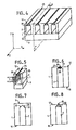
- a substrate 1 has thus been represented in which four notches such as 2 have been made. These notches are perpendicular to the face 10 of the substrate. They have, at the bottom of the notch, a narrowing 20. All these notches have the same depth and do not reach the face 11 opposite the face.
- the narrows, such as 20, are filled with a non-magnetic material.
- a non-magnetic material For example, a glass-based material is poured. A structure such as that of FIG. 2 is thus obtained.
- a plate 3 of magnetic material is fixed on the face 10 of the substrate. This plate closes the notches previously made and will close the magnetic circuit of the head.
- the face 11 of the substrate is machined parallel to the bottoms of the notches.
- a structure is thus obtained as shown in FIG. 4.
- the precision of the width of the air gap is adjusted by the machining thickness of the face 11.
- the structure thus produced is cut into individual magnetic circuits.
- the cut is made according to planes such as P located between the notches and parallel to the axis of the notches.
- the structure of FIG. 4 being placed in an XYZ triede, with the faces 10 and 11 parallel to the XZ planes, the planes such as P are parallel to the ZY plane.
- each magnetic circuit is equipped with a coil 7 as shown in FIG. 5. This coil is wound by the notch 2 around a branch of the magnetic circuit 2.
- the active face 11 of the head comprising the air gap 25 is coated with a layer of a strongly magnetic material such as that known under the name of Sendust (Fe x Si y Al z ). This operation can also be done before cutting into individual magnetic circuits. This coating of highly magnetic material covers the face 11 except the air gap 25 of each magnetic circuit.
- each notch 2 can be done in different ways.
- the notch 2 is produced using an abrasive disc or grinding wheel whose profile has the shape of the notch 2 and its shrinkage 20 to be obtained.
- the abrasive disc is therefore shouldered to the dimensions of the notch to be obtained.
- the notch 2 is produced by the successive passages of two abrasive discs.
- a first disc of sufficient width thus produces the notch 2 necessary for the passage of the winding, then a second abrasive disc of small width and of suitable profile shrinks 20 in the bottom of the notch 2.
- the non-magnetic material of the notch glass, for example
- the coefficient of expansion of the cast material must also approach that of the substrate A to facilitate the deposition of "sendust".
- the magnetic material plate 3 can be made of a material such as a ferrite single crystal or a polycrystalline ferrite. Its bonding on the substrate 1 can be done using molten or sprayed glass, or using an epoxy resin for example. The thickness of the plate 3 is more or less important depending on the height of the head to be obtained.
- the machining of the face 11 of the substrate to obtain the face 12 activates the magnetic head and its air gap 25 is done by grinding completed by a polishing finish of the face 12 obtained.
- the width of the non-magnetic part (air gap 25) is a function of this machining and therefore of the thickness of material removed.
- the width e of the air gap 25 can vary between 50 and 150 micrometers, for example, according to technical needs.
- the shape of the constriction 20 can be rounded as shown in the embodiment of Figures 1 to 5.
- the constriction 20 is then determined by a curved surface whose convexity is directed towards the face 11 of the substrate. After machining the face 11, an air gap defined by two well delimited edges is then obtained.
- the narrowing 20 of the air gap can be defined by two parallel faces 22 and 23.
- the constriction 20 can also be delimited by two faces 22 and 23 forming an angle, the point of which is directed towards the face 11 of the substrate 1.
- the air gap 25 of the magnetic head is formed by the material located between the two faces 22 and 23.
- the production method providing for a narrowing 20 as shown in FIGS. 7 and 8 will make it possible to control the thickness as well as the width of the air gap 25.
- the width of the air gap 25 can be adjusted to a value between 50 and 150 micrometers. A value that seems to be satisfactory is a width of 80 micrometers.
- the substrate does not prejudge the type of winding.
- winding is wound around a part of the magnetic circuit and passing through the notch 2.
- pre-molded coils are provided which are inserted into a series of small studs provided at the base of the substrate (on the face 10) of the active face by machining, passage of a diamond disc in X - Y before bonding.
- Figures 9 and 10 show such an exemplary embodiment.
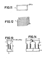
- the substrate 1 undergoes machining along the axes OX and OY of FIG. 10 so as to produce pads such as 26 and 27. Then prefabricated windings such as that shown in FIGS. 11 and 12 are mounted on these studs. The plate 3 is then bonded to the face 10 of the substrate. A structure is thus obtained as shown in FIGS. 9 and 10.
- the face 11 is then machined so as to reveal the air gaps 25, and each magnetic head is cut out.
- a magnetic head comprising the studs 26 and 27 by cutting along the axes VV ′, WW ′ and FF ′, GG ′.
- the head obtained is of the type shown in FIGS. 13 and 14.
- the machining of the studs is such that their dimensions are as follows: - a ⁇ 200 micrometers - d ⁇ 800 micrometers - c ⁇ 400 micrometers
- each head makes it possible to obtain a head such that in FIGS. 13 and 14 it has for: - length L ⁇ 2300 micrometers - width M ⁇ 300 to 350 micrometers - height h ⁇ 600 to 700 micrometers
- a coil as shown in Figures 11 and 12 must have dimensions allowing its nesting on a stud. It will for example be made with wire of 30 micrometers in diameter, its height will be approximately 400 micrometers and its internal dimensions, greater than those of a studs, that is to say greater than 800 ⁇ 200 micrometers.
- a non-magnetic material eg glass
- a magnetic substrate polycrystalline or monocrystalline ferrite
- This embodiment allows, at the air gap, to obtain better guidance of the magnetic flux. It also makes it possible to work with large substrates.
- the three main advantages of the invention are: - a simple industrial design, - very few machining operations. - collective treatment of magnetic heads.
- the invention thus makes it possible to produce a magnetic head comprising an air gap 25 delimited in a substrate 1 by two faces 23, 24 forming an angle the tip of which is directed towards the active recording face 12 of the head as shown in figure 8.
- the head of the invention may also have its air gap 25 delimited by a curved surface whose convexity is directed towards the active face 12 for recording the head as shown in FIG. 5.
Landscapes
- Engineering & Computer Science (AREA)
- Manufacturing & Machinery (AREA)
- Magnetic Heads (AREA)
Priority Applications (1)
| Application Number | Priority Date | Filing Date | Title |
|---|---|---|---|
| DE19883855329 DE3855329T2 (de) | 1988-11-08 | 1988-11-08 | Herstellungsverfahren eines Aufzeichnungs-/Wiedergabemagnetkopfes |
Applications Claiming Priority (1)
| Application Number | Priority Date | Filing Date | Title |
|---|---|---|---|
| FR8714824A FR2622340B1 (fr) | 1987-10-27 | 1987-10-27 | Procede de realisation d'une tete magnetique d'enregistrement/lecture et tete realisee selon ce procede |
Publications (2)
| Publication Number | Publication Date |
|---|---|
| EP0367880A1 true EP0367880A1 (de) | 1990-05-16 |
| EP0367880B1 EP0367880B1 (de) | 1996-05-29 |
Family
ID=9356194
Family Applications (1)
| Application Number | Title | Priority Date | Filing Date |
|---|---|---|---|
| EP19880402807 Expired - Lifetime EP0367880B1 (de) | 1987-10-27 | 1988-11-08 | Herstellungsverfahren eines Aufzeichnungs-/Wiedergabemagnetkopfes |
Country Status (2)
| Country | Link |
|---|---|
| EP (1) | EP0367880B1 (de) |
| FR (1) | FR2622340B1 (de) |
Cited By (1)
| Publication number | Priority date | Publication date | Assignee | Title |
|---|---|---|---|---|
| CN100350458C (zh) * | 1994-06-30 | 2007-11-21 | 国际商业机器公司 | 一种伺服写头 |
Families Citing this family (1)
| Publication number | Priority date | Publication date | Assignee | Title |
|---|---|---|---|---|
| FR2648940B1 (fr) * | 1989-06-27 | 1991-09-06 | Thomson Csf | Procede de realisation de tete magnetique multipiste et tete magnetique multipiste |
Citations (7)
| Publication number | Priority date | Publication date | Assignee | Title |
|---|---|---|---|---|
| DE924350C (de) * | 1953-05-22 | 1955-02-28 | Armin Dr Burkhard | Verfahren zum Aufbau von Magnetkoepfen mit einem oder mehreren Arbeitsspalten |
| FR1159994A (fr) * | 1956-10-01 | 1958-07-04 | Bull Sa Machines | Tête magnétique de lecture et d'enregistrement et son procédé de fabrication |
| US3229355A (en) * | 1962-01-02 | 1966-01-18 | Ibm | Method of making a magnetic transducer head |
| US3613228A (en) * | 1969-07-02 | 1971-10-19 | Ibm | Manufacture of multielement magnetic head assemblies |
| DE2041015A1 (de) * | 1970-08-18 | 1972-02-24 | Bogen Gmbh W | Verfahren zur Herstellung von Magnetkoepfen in ein- und/oder mehrspuriger Ausfuehrung zum Aufzeichnen,Wiedergeben und Loeschen von Magnetogrammen |
| DE2751211A1 (de) * | 1977-11-16 | 1979-05-17 | Grundig Emv | Loeschkopf und verfahren zu seiner herstellung |
| EP0052708A1 (de) * | 1980-11-20 | 1982-06-02 | International Business Machines Corporation | Einspur-Magnetkopfeinheit |
Family Cites Families (5)
| Publication number | Priority date | Publication date | Assignee | Title |
|---|---|---|---|---|
| JPS5528532A (en) * | 1978-08-18 | 1980-02-29 | Pioneer Electronic Corp | Manufacture method of head |
| JPS60107712A (ja) * | 1983-11-17 | 1985-06-13 | Tdk Corp | 磁気ヘッドの製造方法 |
| JPS60175204A (ja) * | 1984-02-20 | 1985-09-09 | Akai Electric Co Ltd | 磁気ヘツド |
| JPS6139207A (ja) * | 1984-07-28 | 1986-02-25 | Victor Co Of Japan Ltd | 磁気ヘツドの磁気空隙の形成法 |
| JPS61292209A (ja) * | 1985-06-19 | 1986-12-23 | Alps Electric Co Ltd | 磁気ヘツドの製造方法 |
-
1987
- 1987-10-27 FR FR8714824A patent/FR2622340B1/fr not_active Expired - Fee Related
-
1988
- 1988-11-08 EP EP19880402807 patent/EP0367880B1/de not_active Expired - Lifetime
Patent Citations (7)
| Publication number | Priority date | Publication date | Assignee | Title |
|---|---|---|---|---|
| DE924350C (de) * | 1953-05-22 | 1955-02-28 | Armin Dr Burkhard | Verfahren zum Aufbau von Magnetkoepfen mit einem oder mehreren Arbeitsspalten |
| FR1159994A (fr) * | 1956-10-01 | 1958-07-04 | Bull Sa Machines | Tête magnétique de lecture et d'enregistrement et son procédé de fabrication |
| US3229355A (en) * | 1962-01-02 | 1966-01-18 | Ibm | Method of making a magnetic transducer head |
| US3613228A (en) * | 1969-07-02 | 1971-10-19 | Ibm | Manufacture of multielement magnetic head assemblies |
| DE2041015A1 (de) * | 1970-08-18 | 1972-02-24 | Bogen Gmbh W | Verfahren zur Herstellung von Magnetkoepfen in ein- und/oder mehrspuriger Ausfuehrung zum Aufzeichnen,Wiedergeben und Loeschen von Magnetogrammen |
| DE2751211A1 (de) * | 1977-11-16 | 1979-05-17 | Grundig Emv | Loeschkopf und verfahren zu seiner herstellung |
| EP0052708A1 (de) * | 1980-11-20 | 1982-06-02 | International Business Machines Corporation | Einspur-Magnetkopfeinheit |
Non-Patent Citations (5)
| Title |
|---|
| PATENT ABSTRACTS OF JAPAN, vol. 10, no. 195 (P-475)[2251], 9 juillet 1986; & JP-A-61 39 207 (VICTOR CO. OF JAPAN LTD) 25-02-1986 * |
| PATENT ABSTRACTS OF JAPAN, vol. 10, no. 22 (P-424)[2079], 28 janvier 1986; & JP-A-60 175 204 (AKAI DENKI K.K.) 09-09-1985 * |
| PATENT ABSTRACTS OF JAPAN, vol. 11, no. 156 (P-578)[2603], 21 mai 1987; & JP-A-61 292 209 (ALPS ELECTRIC CO. LTD) 23-12-1986 * |
| PATENT ABSTRACTS OF JAPAN, vol. 4, no. 58 (P-9)[540], 30 avril 1980; & JP-A-55 28 532 (PIONEER K.K.) 29-02-1980 * |
| PATENT ABSTRACTS OF JAPAN, vol. 9, no. 259 (P-397)[1982], 17 octobre 1985; & JP-A-60 107 712 (TDK K.K.) 13-06-1985 * |
Cited By (1)
| Publication number | Priority date | Publication date | Assignee | Title |
|---|---|---|---|---|
| CN100350458C (zh) * | 1994-06-30 | 2007-11-21 | 国际商业机器公司 | 一种伺服写头 |
Also Published As
| Publication number | Publication date |
|---|---|
| EP0367880B1 (de) | 1996-05-29 |
| FR2622340B1 (fr) | 1995-06-16 |
| FR2622340A1 (fr) | 1989-04-28 |
Similar Documents
| Publication | Publication Date | Title |
|---|---|---|
| EP0618568B1 (de) | Dünnschicht-Aufnahme-Wiedergabemagnetkopf und Herstellungsverfahren | |
| FR2559293A1 (fr) | Nouvelle tete magnetique d'ecriture et de lecture pour enregistrement magnetique et son procede de fabrication | |
| FR2630244A1 (fr) | Dispositif d'ecriture et de lecture sur un support magnetique et son procede de fabrication | |
| FR2562304A1 (fr) | Tete de transducteur magnetique | |
| EP0406362B1 (de) | Herstellungsverfahren eines aufnahme-/wiedergabekopfes und nach diesem verfahren erhaltener kopf | |
| FR2559294A1 (fr) | Nouvelle tete magnetique d'ecriture et de lecture pour enregistrement perpendiculaire et son procede de fabrication | |
| EP0452193B1 (de) | Herstellungsverfahren von einem magnetischen Wiedergabe-Aufzeichnungskopf | |
| FR2532458A1 (fr) | Tete de transducteur magnetique notamment pour l'enregistrement en mode perpendiculaire | |
| FR2573902A1 (fr) | Tete de transducteur magnetique | |
| EP0367880B1 (de) | Herstellungsverfahren eines Aufzeichnungs-/Wiedergabemagnetkopfes | |
| FR2558000A1 (fr) | Tete de transducteur magnetique. | |
| FR2633429A1 (fr) | Procede de realisation de la planeite d'une face active pour tete magnetique d'enregistrement/lecture | |
| EP0266266B1 (de) | Verfahren zur Herstellung einer plattenförmigen gewickelten magnetischen Lese- und -Wiedergabekopfanordnung und eine Kopfanordnung durch dieses Verfahren hergestellt | |
| FR2500672A1 (fr) | Tete magnetique a films minces et son procede de fabrication | |
| EP0338063B1 (de) | Aufzeichnungs-wiedergabemagnetkopf und verfahren zu seiner herstellung | |
| EP0392907A1 (de) | Herstellungsverfahren für eine Vorrichtung mit Dünnschicht-Filmstruktur | |
| EP0348265B1 (de) | Herstellungsverfahren eines Aufzeichnungs-Wiedergabemagnetkopfes aus einem magnetischen Substrat | |
| FR2610129A1 (fr) | Tete magnetique a utiliser pour l'enregistrement vertical | |
| JPH06259717A (ja) | 磁気ヘッド及びその製造方法 | |
| KR100269371B1 (ko) | 광자기디스크용자기헤드 | |
| JPH1091912A (ja) | 磁気ヘッド | |
| EP0550322A1 (de) | Verfahren zur Herstellung eines Magnetkopfes für Schichten mit hohen koercitiven Feldern | |
| JPH08279109A (ja) | 磁気ヘッド及びその製造方法 | |
| JPS5853014A (ja) | 磁気ヘツド製造法 | |
| JPS59198520A (ja) | 磁気ヘツドの製造方法 |
Legal Events
| Date | Code | Title | Description |
|---|---|---|---|
| PUAI | Public reference made under article 153(3) epc to a published international application that has entered the european phase |
Free format text: ORIGINAL CODE: 0009012 |
|
| AK | Designated contracting states |
Kind code of ref document: A1 Designated state(s): BE DE GB IT NL |
|
| 17P | Request for examination filed |
Effective date: 19901109 |
|
| 17Q | First examination report despatched |
Effective date: 19930604 |
|
| RAP1 | Party data changed (applicant data changed or rights of an application transferred) |
Owner name: THOMSON-CSF |
|
| GRAH | Despatch of communication of intention to grant a patent |
Free format text: ORIGINAL CODE: EPIDOS IGRA |
|
| GRAA | (expected) grant |
Free format text: ORIGINAL CODE: 0009210 |
|
| AK | Designated contracting states |
Kind code of ref document: B1 Designated state(s): BE DE GB IT NL |
|
| ITF | It: translation for a ep patent filed | ||
| REF | Corresponds to: |
Ref document number: 3855329 Country of ref document: DE Date of ref document: 19960704 |
|
| GBT | Gb: translation of ep patent filed (gb section 77(6)(a)/1977) |
Effective date: 19960626 |
|
| PLBE | No opposition filed within time limit |
Free format text: ORIGINAL CODE: 0009261 |
|
| STAA | Information on the status of an ep patent application or granted ep patent |
Free format text: STATUS: NO OPPOSITION FILED WITHIN TIME LIMIT |
|
| 26N | No opposition filed | ||
| PGFP | Annual fee paid to national office [announced via postgrant information from national office to epo] |
Ref country code: BE Payment date: 19991109 Year of fee payment: 12 |
|
| PG25 | Lapsed in a contracting state [announced via postgrant information from national office to epo] |
Ref country code: BE Free format text: LAPSE BECAUSE OF NON-PAYMENT OF DUE FEES Effective date: 20001130 |
|
| BERE | Be: lapsed |
Owner name: THOMSON-CSF Effective date: 20001130 |
|
| REG | Reference to a national code |
Ref country code: GB Ref legal event code: IF02 |
|
| PGFP | Annual fee paid to national office [announced via postgrant information from national office to epo] |
Ref country code: GB Payment date: 20041011 Year of fee payment: 17 |
|
| PGFP | Annual fee paid to national office [announced via postgrant information from national office to epo] |
Ref country code: DE Payment date: 20041116 Year of fee payment: 17 |
|
| PGFP | Annual fee paid to national office [announced via postgrant information from national office to epo] |
Ref country code: NL Payment date: 20041117 Year of fee payment: 17 |
|
| PG25 | Lapsed in a contracting state [announced via postgrant information from national office to epo] |
Ref country code: IT Free format text: LAPSE BECAUSE OF NON-PAYMENT OF DUE FEES;WARNING: LAPSES OF ITALIAN PATENTS WITH EFFECTIVE DATE BEFORE 2007 MAY HAVE OCCURRED AT ANY TIME BEFORE 2007. THE CORRECT EFFECTIVE DATE MAY BE DIFFERENT FROM THE ONE RECORDED. Effective date: 20051108 Ref country code: GB Free format text: LAPSE BECAUSE OF NON-PAYMENT OF DUE FEES Effective date: 20051108 |
|
| PG25 | Lapsed in a contracting state [announced via postgrant information from national office to epo] |
Ref country code: NL Free format text: LAPSE BECAUSE OF NON-PAYMENT OF DUE FEES Effective date: 20060601 Ref country code: DE Free format text: LAPSE BECAUSE OF NON-PAYMENT OF DUE FEES Effective date: 20060601 |
|
| GBPC | Gb: european patent ceased through non-payment of renewal fee |
Effective date: 20051108 |
|
| NLV4 | Nl: lapsed or anulled due to non-payment of the annual fee |
Effective date: 20060601 |