EP0367920A2 - Machine-outil - Google Patents
Machine-outil Download PDFInfo
- Publication number
- EP0367920A2 EP0367920A2 EP89115222A EP89115222A EP0367920A2 EP 0367920 A2 EP0367920 A2 EP 0367920A2 EP 89115222 A EP89115222 A EP 89115222A EP 89115222 A EP89115222 A EP 89115222A EP 0367920 A2 EP0367920 A2 EP 0367920A2
- Authority
- EP
- European Patent Office
- Prior art keywords
- tool
- unit
- machine
- holder
- machine tool
- Prior art date
- Legal status (The legal status is an assumption and is not a legal conclusion. Google has not performed a legal analysis and makes no representation as to the accuracy of the status listed.)
- Withdrawn
Links
- 230000008878 coupling Effects 0.000 claims description 15
- 238000010168 coupling process Methods 0.000 claims description 15
- 238000005859 coupling reaction Methods 0.000 claims description 15
- 230000005540 biological transmission Effects 0.000 claims description 7
- 238000004080 punching Methods 0.000 description 4
- 239000000969 carrier Substances 0.000 description 2
- 230000006835 compression Effects 0.000 description 2
- 238000007906 compression Methods 0.000 description 2
- 238000006243 chemical reaction Methods 0.000 description 1
- 238000005516 engineering process Methods 0.000 description 1
Images
Classifications
-
- B—PERFORMING OPERATIONS; TRANSPORTING
- B21—MECHANICAL METAL-WORKING WITHOUT ESSENTIALLY REMOVING MATERIAL; PUNCHING METAL
- B21D—WORKING OR PROCESSING OF SHEET METAL OR METAL TUBES, RODS OR PROFILES WITHOUT ESSENTIALLY REMOVING MATERIAL; PUNCHING METAL
- B21D37/00—Tools as parts of machines covered by this subclass
- B21D37/04—Movable or exchangeable mountings for tools
-
- B—PERFORMING OPERATIONS; TRANSPORTING
- B21—MECHANICAL METAL-WORKING WITHOUT ESSENTIALLY REMOVING MATERIAL; PUNCHING METAL
- B21D—WORKING OR PROCESSING OF SHEET METAL OR METAL TUBES, RODS OR PROFILES WITHOUT ESSENTIALLY REMOVING MATERIAL; PUNCHING METAL
- B21D28/00—Shaping by press-cutting; Perforating
- B21D28/02—Punching blanks or articles with or without obtaining scrap; Notching
- B21D28/12—Punching using rotatable carriers
-
- B—PERFORMING OPERATIONS; TRANSPORTING
- B21—MECHANICAL METAL-WORKING WITHOUT ESSENTIALLY REMOVING MATERIAL; PUNCHING METAL
- B21D—WORKING OR PROCESSING OF SHEET METAL OR METAL TUBES, RODS OR PROFILES WITHOUT ESSENTIALLY REMOVING MATERIAL; PUNCHING METAL
- B21D37/00—Tools as parts of machines covered by this subclass
- B21D37/04—Movable or exchangeable mountings for tools
- B21D37/06—Pivotally-arranged tools, e.g. disengageable
-
- B—PERFORMING OPERATIONS; TRANSPORTING
- B21—MECHANICAL METAL-WORKING WITHOUT ESSENTIALLY REMOVING MATERIAL; PUNCHING METAL
- B21D—WORKING OR PROCESSING OF SHEET METAL OR METAL TUBES, RODS OR PROFILES WITHOUT ESSENTIALLY REMOVING MATERIAL; PUNCHING METAL
- B21D43/00—Feeding, positioning or storing devices combined with, or arranged in, or specially adapted for use in connection with, apparatus for working or processing sheet metal, metal tubes or metal profiles; Associations therewith of cutting devices
-
- B—PERFORMING OPERATIONS; TRANSPORTING
- B23—MACHINE TOOLS; METAL-WORKING NOT OTHERWISE PROVIDED FOR
- B23D—PLANING; SLOTTING; SHEARING; BROACHING; SAWING; FILING; SCRAPING; LIKE OPERATIONS FOR WORKING METAL BY REMOVING MATERIAL, NOT OTHERWISE PROVIDED FOR
- B23D31/00—Shearing machines or shearing devices covered by none or more than one of the groups B23D15/00 - B23D29/00; Combinations of shearing machines
-
- Y—GENERAL TAGGING OF NEW TECHNOLOGICAL DEVELOPMENTS; GENERAL TAGGING OF CROSS-SECTIONAL TECHNOLOGIES SPANNING OVER SEVERAL SECTIONS OF THE IPC; TECHNICAL SUBJECTS COVERED BY FORMER USPC CROSS-REFERENCE ART COLLECTIONS [XRACs] AND DIGESTS
- Y10—TECHNICAL SUBJECTS COVERED BY FORMER USPC
- Y10T—TECHNICAL SUBJECTS COVERED BY FORMER US CLASSIFICATION
- Y10T29/00—Metal working
- Y10T29/50—Convertible metal working machine
-
- Y—GENERAL TAGGING OF NEW TECHNOLOGICAL DEVELOPMENTS; GENERAL TAGGING OF CROSS-SECTIONAL TECHNOLOGIES SPANNING OVER SEVERAL SECTIONS OF THE IPC; TECHNICAL SUBJECTS COVERED BY FORMER USPC CROSS-REFERENCE ART COLLECTIONS [XRACs] AND DIGESTS
- Y10—TECHNICAL SUBJECTS COVERED BY FORMER USPC
- Y10T—TECHNICAL SUBJECTS COVERED BY FORMER US CLASSIFICATION
- Y10T83/00—Cutting
- Y10T83/869—Means to drive or to guide tool
- Y10T83/8727—Plural tools selectively engageable with single drive
- Y10T83/8732—Turret of tools
Definitions
- the invention relates to a machine tool with an open on three sides, preferably approximately C-shaped machine frame, an attached to the machine frame, vertically movable by a drive carriage, upper tool holder with at least two tool holders arranged side by side with corresponding upper tools, a lower tool holder attached to the machine frame with a Corresponding number of tool holders arranged next to one another with corresponding lower tools and a die plate which is clamped on the lower tool carrier and is preferably arranged in a holder and has the tool holders.
- the known machine tool from which the invention is based is a multi-punch machine tool with at least three, often also with five tool receptacles arranged side by side in the upper tool carrier with upper tools arranged therein, in particular punching dies, and a corresponding number of lower tool holders with corresponding lower tools, in particular punching dies.
- the upper tools can be changed individually or all particularly quickly in that a closure cap which closes all tool receptacles on the upper tool carrier on the end faces is pivotably articulated and can be locked with this. When the closure cap is open, a single upper tool or all upper tools can simply be pulled horizontally out of the tool holders open horizontally on one side, or other upper tools can be inserted horizontally accordingly.
- the tool holders on the lower tool carrier are located in a die plate, which in turn is inserted in a socket plate.
- a die plate By inserting the die plate into the socket of the saddle plate and locking it in this socket, the die plate can always be brought into its desired position with just a few handles. It depends on the number and size of the upper tools and lower tools, how many Upper tools and lower tools can be used here simultaneously. Depending on the number and size of the lower tools, there are various interchangeable die plates.
- a tool unit comprising a guide frame, in particular a cutting unit or notching unit (DE-AS 10 04 891).
- This known machine tool has a notching unit as the tool unit.
- the upper tool is guided in a guide frame in a vertically displaceable manner in guide rails and has at the upper end a hammer head-like coupling means which can be inserted into a corresponding coupling means, designed here as a T-slot, on the upper tool carrier.
- the guide frame of the tool unit which receives the lower tool, has an inverted T-shaped plate as coupling means at the lower end, which can be inserted into a coupling means designed as a T-groove on the lower tool carrier.
- the entire tool unit is thus inserted in total in the longitudinal direction of the machine frame, coupling from the open end face, between the upper and lower tool carriers.
- the invention is based on the object of designing and developing the known machine tool described at the outset in such a way that a self-guided tool unit can be used here in the same flexible manner as the normal upper and lower tools.
- a tool unit comprising an upper tool and a lower tool in a guide frame, in particular a cutting unit or a notching unit, is arranged and is drivingly coupled to the upper tool carrier.
- a self-guided tool unit can also be integrated into the multi-punch machine tool from which the invention is based if the tool unit is treated as a lower tool, but the upper tool in the tool unit is coupled with the upper tool carrier in terms of drive. Then you can even keep the quick change system of the known machine tool with the cap.
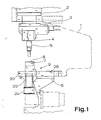
- the machine tool shown in a side view in FIG. 1 initially has a machine frame 1 that is open on three sides, preferably approximately C-shaped.
- an upper tool carrier 3 which can be moved vertically by a schematically illustrated drive slide 2 appropriate.
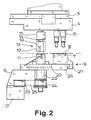
- the upper tool carrier 3 has, as shown in particular in FIG. 2, a plurality of tool receptacles 4 arranged next to one another with correspondingly arranged upper tools 5.
- two punch stamps can be seen as upper tools 5.
- a lower tool carrier 6 with a corresponding number of tool receptacles 7 arranged next to one another with corresponding lower tools 8.
- first two punching dies corresponding to the upper tools 5 designed as stamping dies are shown as lower tools 8.
- the die plate 9 can be exchanged in order to compare matching lower tools 8 with correspondingly replaced upper tools 5.
- a tool unit 13 in particular a cutting unit or notching unit, comprising an upper tool 10 and a lower tool 11 in a guide frame 12, is arranged on the die plate 9 instead of a lower tool in a corresponding tool holder 7 and is coupled in terms of drive with the upper tool carrier 3 is.
- the upper tool carrier 3 is fundamentally prepared for holding five upper tools 5 of normal size, that is to say five punching dies, and thus has a total of five tool holders 4.
- the lower tool carrier 6 in principle has the space for five corresponding tool holders 7.
- the tool unit 13 takes the place of several normal lower tools, namely three lower tools here.
- the tool unit 13 is arranged so that it is positioned off-center on the die plate 9.
- the tool unit 13 must be inserted in a non-positive coupling between the upper and lower tool carriers 3, 6.
- the force Closely coupling to the upper tool carrier 3 could first be implemented according to the system in that the tool unit has a coupling part connected to the upper tool and the coupling part is inserted into a corresponding tool holder in the upper tool carrier instead of an upper tool.
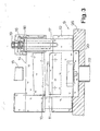
- the upper tool 10 of the tool unit 13 has a force transmission surface 14 pointing towards the upper tool carrier 3 and that a tool holder 4 in the upper tool carrier 3 is arranged on the force transmission surface 14 pressure ram 15.
- the pressure tappet 15 can be seen particularly well in FIG. 2. 3 shows how the pressure tappet 15 is seated only on the force transmission surface 14.
- the tool unit 13 is designed such that its lower tool 11 is fixed, while the upper tool 10 can be actively moved up or down by the upper tool carrier 3.
- the prestressing of the upper tool 10 can be generated by various means.
- springs 16, that is to say tension springs, compression springs, helical compression springs, gas pressure springs, etc. are recommended as the pretensioning means.
- the pretensioning of the upper tool 10 is generated by two plate spring stacks (FIG. 3). 3 shows in the context that, according to the preferred teaching of the invention, the guide frame 12 is the tool unit 13 is designed as a column guide.
- the springs 16, in particular the plate springs of the plate spring stack are arranged in corresponding guide columns 17. It can be clearly seen in FIG.
- the upper tool 10 here the upper knife
- the springs 16 designed as a stack of disc springs being arranged inside the guide columns 17.
- the known machine tool with a tool unit explained at the outset is not yet flexible enough in that, for example, a sequence of miter cuts with different miter angles between two cuts would make it necessary to replace the tool unit with another tool unit having the following miter angle.
- a further improvement in flexibility is also recommended in the teaching of the invention in that the tool holder 7 for the tool unit 13 is designed to be rotationally symmetrical, in particular as a rotary mount, and the tool unit 13 is fastened on a turntable 20 which can be rotated in the tool holder 7 in the horizontal plane .
- the turntable 20 can be seen particularly well in FIGS. 2 and 3.
- a self-guided tool unit 13 creates the possibility of rotating the turntable 20 relative to the lower tool carrier 6 or the die plate 9, for .
- a cutting unit as a tool unit 13 practically any desired miter angle. This is of course much easier than changing the tool unit 13 itself.
- this is inexpensive since tool units 13 do not have to be kept available for different miter angles.
- Corresponding handling advantages also result for other types of tool units with non-rotationally symmetrical tools.
- the rotary movement of the turntable 20 can be limited in one or in both directions of rotation by stops. Intermediate settings by locking at particularly frequently occurring angles of rotation, for example correspondingly frequently selected miter angles, can also be provided. None of this is shown in the drawing. It is shown in FIGS. 1 and 2, however, that a motorized rotary drive 21, in particular a hydraulic motor, is provided for the turntable 20.
- a hydraulic motor as a rotary drive 21 is particularly expedient because hydraulic medium has to be supplied at many points anyway to drive the machine tool.
- the rotary drive 21 can be coupled with the turntable 20 in terms of drive technology is left to the constructive ideas of the experts.
- the ring gear could also be arranged on the upper outer edge or elsewhere on the turntable.
- the turntable 20 has a drive shaft 22 projecting downward through the die plate 9 and the rotary drive 21 engages the drive shaft 22.
- the rotary drive 21 could act directly on the drive shaft 22, for example the drive shaft 22 could simultaneously be the output shaft of the rotary drive 21.
- the power transmission is solved differently here, namely in that the rotary drive 21 has an output gear 23 and the drive Shaft 22 carries a drive gear 24 and both gears 23, 24 are connected to one another via a chain or a toothed belt 25.
- gear wheels friction wheels in connection with a friction wheel drive could also be used.
- connection of the tool unit 13, that is to say the drive coupling of the tool unit 13 to the upper tool carrier 3 must also permit a rotary movement.
- the rotationally symmetrical design or the approval of a rotary movement is given without constraint if only a pressure tappet 15 is provided, which is seated on the force transmission surface 14, as corresponds to a preferred teaching of the invention. Otherwise, other coupling systems that allow a rotational movement can also be used.
- the die plate 9 is a single continuous plate, which on the one hand has normal tool holders 7 for normal lower tools 8, and on the other hand the specially designed tool holder 7 for the turntable 20 for mounting the tool unit 13.
- the exemplary embodiment of a machine tool according to the invention shown in the drawing is now different and specially designed insofar as the machine tool always carries the turntable 20 and the rotary drive 21, etc. Nevertheless, this machine tool can be flexibly converted, for example, to a die plate 9 with five similar, normal tool holders 7.
- the die plate 9 has a lower saddle plate that receives the turntable 20 in the tool holder 8 designed as a rotary mount 26 and an upper plate 27 which can be clamped onto the saddle plate 26 and which accommodates the remaining tool holders 7 for lower tools 8.
- Fig. 2 shows that the top plate 27, the two normal Tool holders 7 for normal, designed as punch dies lower tools 8 is attached to the saddle plate 26 by fastening screws. It leaves the area of the turntable 20 free, so that the tool unit 13 can be attached there as shown and there is sufficient space for executing the rotary movement.
Landscapes
- Engineering & Computer Science (AREA)
- Mechanical Engineering (AREA)
- Mounting, Exchange, And Manufacturing Of Dies (AREA)
- Punching Or Piercing (AREA)
- Automatic Tool Replacement In Machine Tools (AREA)
Applications Claiming Priority (2)
| Application Number | Priority Date | Filing Date | Title |
|---|---|---|---|
| DE3838198A DE3838198A1 (de) | 1988-11-08 | 1988-11-08 | Werkzeugmaschine |
| DE3838198 | 1988-11-08 |
Publications (2)
| Publication Number | Publication Date |
|---|---|
| EP0367920A2 true EP0367920A2 (fr) | 1990-05-16 |
| EP0367920A3 EP0367920A3 (fr) | 1990-12-12 |
Family
ID=6366915
Family Applications (1)
| Application Number | Title | Priority Date | Filing Date |
|---|---|---|---|
| EP19890115222 Withdrawn EP0367920A3 (fr) | 1988-11-08 | 1989-08-18 | Machine-outil |
Country Status (6)
| Country | Link |
|---|---|
| US (1) | US4928377A (fr) |
| EP (1) | EP0367920A3 (fr) |
| JP (1) | JPH02179328A (fr) |
| KR (1) | KR910007128B1 (fr) |
| CA (1) | CA2001662A1 (fr) |
| DE (1) | DE3838198A1 (fr) |
Cited By (1)
| Publication number | Priority date | Publication date | Assignee | Title |
|---|---|---|---|---|
| CN108406910A (zh) * | 2018-02-12 | 2018-08-17 | 苏州佳世达电通有限公司 | 成型设备及取放治具 |
Families Citing this family (8)
| Publication number | Priority date | Publication date | Assignee | Title |
|---|---|---|---|---|
| AU647927B2 (en) * | 1991-06-03 | 1994-03-31 | John Lysaght (Australia) Limited | Press tool |
| JP3930612B2 (ja) * | 1997-08-07 | 2007-06-13 | 本田技研工業株式会社 | コンロッド取付部材の締付装置 |
| CN104647461A (zh) * | 2013-11-20 | 2015-05-27 | 铜陵市大成轧辊有限责任公司 | 一种切割装置 |
| CN106964837B (zh) * | 2017-05-31 | 2019-05-14 | 温州豪冠锁业科技有限公司 | 一种用于锁具快速切断装置 |
| CN107983824A (zh) * | 2017-12-13 | 2018-05-04 | 温州泰昌铁塔制造有限公司 | 一种手动可调切角模架 |
| CN109366185B (zh) * | 2018-11-22 | 2023-11-03 | 永康市大山机械有限公司 | 自动旋转滚切冲压机床 |
| CN110000423B (zh) * | 2019-04-18 | 2024-02-20 | 浙江天弘新材料有限公司 | 一种钢带分切机 |
| CN112025415A (zh) * | 2020-10-14 | 2020-12-04 | 山东辰榜数控装备有限公司 | 一种五轴数控机床 |
Family Cites Families (16)
| Publication number | Priority date | Publication date | Assignee | Title |
|---|---|---|---|---|
| DE1004891B (de) * | 1952-07-02 | 1957-03-21 | Alois Jarma Dipl Ing | Schnellwechseleinrichtung fuer Werkzeuge in Maschinen mit auf und ab gehendem Druckstoessel |
| US3029677A (en) * | 1958-05-28 | 1962-04-17 | Western Electric Co | Material cutters for multiple tool presses |
| GB1182892A (en) * | 1968-05-31 | 1970-03-04 | Pressen Und Scherenbau Erfurt | Improvements in and relating to Clamping Devices. |
| US3942431A (en) * | 1974-05-01 | 1976-03-09 | General Machine Industries Corporation | Press having travelling die set |
| FR2409812A1 (fr) * | 1977-11-26 | 1979-06-22 | Behrens Ag C | Presse a decouper pour le travail de pieces en forme de plaques, en particulier de toles |
| JPS5825527B2 (ja) * | 1978-07-10 | 1983-05-27 | 株式会社小松製作所 | 多段打抜き装置 |
| FR2510918A1 (fr) * | 1981-08-07 | 1983-02-11 | Libaud Procedes Ateliers Berna | Dispositif de poinconnage comportant des moyens de devetissage portes par sa tige de verin et machine poinconneuse equipee de ce dispositif |
| FR2530507A1 (fr) * | 1982-07-21 | 1984-01-27 | Lefils Michel | Construction simplifiee des outillages, permettant d'etendre l'utilisation des outils a la bande, dans la fabrication en petite et moyenne series des articles metalliques |
| GB2146569B (en) * | 1983-09-22 | 1986-12-10 | Smeets Gerard G F | Press or punching machine |
| DE3339503C2 (de) * | 1983-10-31 | 1985-09-05 | Dietz NC-Werkzeugsysteme, 8374 Viechtach | Stanzmaschine und Werkzeugsatz für Stanzmaschinen |
| DE3440093A1 (de) * | 1984-11-02 | 1986-05-07 | Fa. Muhr und Bender, 5952 Attendorn | Werkzeugmaschine, insbesondere stanze |
| DE3448090A1 (de) * | 1984-11-14 | 1986-09-11 | C. Behrens Ag, 3220 Alfeld | Schneidpresse mit einer einzelkopfstation |
| JPS61180618A (ja) * | 1985-02-06 | 1986-08-13 | Honda Motor Co Ltd | 折曲げ加工製品の製造方法および装置 |
| US4691554A (en) * | 1985-06-12 | 1987-09-08 | Murphy William P | Die transfer system |
| US4587830A (en) * | 1985-07-15 | 1986-05-13 | Mills Charles E | Punch press with quick-change die set |
| US4738018A (en) * | 1985-11-12 | 1988-04-19 | Ebrahim Ebrahimian | Combined bending and cutting machine for metal sheet and plate |
-
1988
- 1988-11-08 DE DE3838198A patent/DE3838198A1/de active Granted
-
1989
- 1989-08-18 EP EP19890115222 patent/EP0367920A3/fr not_active Withdrawn
- 1989-10-19 US US07/424,031 patent/US4928377A/en not_active Expired - Fee Related
- 1989-10-27 CA CA002001662A patent/CA2001662A1/fr not_active Abandoned
- 1989-10-30 JP JP1280008A patent/JPH02179328A/ja active Pending
- 1989-11-07 KR KR1019890016171A patent/KR910007128B1/ko not_active Expired
Cited By (1)
| Publication number | Priority date | Publication date | Assignee | Title |
|---|---|---|---|---|
| CN108406910A (zh) * | 2018-02-12 | 2018-08-17 | 苏州佳世达电通有限公司 | 成型设备及取放治具 |
Also Published As
| Publication number | Publication date |
|---|---|
| DE3838198A1 (de) | 1990-05-10 |
| EP0367920A3 (fr) | 1990-12-12 |
| KR910007128B1 (ko) | 1991-09-18 |
| US4928377A (en) | 1990-05-29 |
| DE3838198C2 (fr) | 1990-08-23 |
| KR900007503A (ko) | 1990-06-01 |
| JPH02179328A (ja) | 1990-07-12 |
| CA2001662A1 (fr) | 1990-05-08 |
Similar Documents
| Publication | Publication Date | Title |
|---|---|---|
| EP0468335B1 (fr) | Outil pour le sertissage d'un connecteur à un conducteur et une isolation | |
| EP1103320A1 (fr) | Machine à border | |
| DE2213779A1 (de) | Vorrichtung für die Demontage und Montage von Reifen | |
| EP0513023B1 (fr) | Unite de commande d'un centre d'usinage modulaire | |
| DE3821308C1 (fr) | ||
| EP0367920A2 (fr) | Machine-outil | |
| DE2300669A1 (de) | Presse fuer material verformende bearbeitung | |
| DE2538605A1 (de) | Stanzvorrichtung | |
| DE3446936C2 (de) | Werkzeugstempelhalterung in einer doppeltwirkenden Ziehpresse zur Verformung von großflächigen Metallblechen | |
| DE69002108T2 (de) | Vorrichtung zum Bearbeiten plattenförmiger Werkstoffe. | |
| DE2928950C2 (de) | Vorrichtung zum Entnehmen von Gärfutter aus Fahrsilos | |
| DE2838733C2 (de) | Profilstahlschere und/oder -stanze | |
| EP0143257A1 (fr) | Raccordement d'outil d'une presse de découpage, notamment d'une presse de découpage à plateau revolver, pour le changement d'outil | |
| DE3709018C2 (de) | Vorrichtung zum Biegebearbeiten von Blechtafeln | |
| DE2659108C2 (de) | Verzahntes Werkzeug zum spanenden Entgraten von Zahnrädern | |
| EP0266625B1 (fr) | Support d'outil supérieur pour un poinçon ou un élément similaire | |
| DE4102941C2 (de) | Vorrichtung zum Höhenverlagern einer Fahrzeugfensterscheibe | |
| DE69701828T2 (de) | Vorrichtung zum automatischen Zuführen von Borstenbehältern oder Borstenkassetten für Bürstenherstellungsmaschinen | |
| DE3844681A1 (de) | Werkzeugmaschine | |
| EP0180146A2 (fr) | Poinçonneuse | |
| CH667238A5 (de) | Klebebindemaschine. | |
| DE69217898T2 (de) | Vorrichtung zum Bearbeiten von Produkten aus Metall | |
| DE3040400C1 (de) | Be- und/oder Entladegeraet fuer Pressen,Stanzen o.dgl. Werkzeugmaschinen | |
| DE4233233C2 (de) | Handhebelpresse | |
| EP0367919A2 (fr) | Machine-outil |
Legal Events
| Date | Code | Title | Description |
|---|---|---|---|
| PUAI | Public reference made under article 153(3) epc to a published international application that has entered the european phase |
Free format text: ORIGINAL CODE: 0009012 |
|
| 17P | Request for examination filed |
Effective date: 19891228 |
|
| AK | Designated contracting states |
Kind code of ref document: A2 Designated state(s): AT BE CH DE ES FR GB GR IT LI NL SE |
|
| PUAL | Search report despatched |
Free format text: ORIGINAL CODE: 0009013 |
|
| AK | Designated contracting states |
Kind code of ref document: A3 Designated state(s): AT BE CH DE ES FR GB GR IT LI NL SE |
|
| 17Q | First examination report despatched |
Effective date: 19920127 |
|
| STAA | Information on the status of an ep patent application or granted ep patent |
Free format text: STATUS: THE APPLICATION IS DEEMED TO BE WITHDRAWN |
|
| 18D | Application deemed to be withdrawn |
Effective date: 19930728 |