EP0367950B1 - Mischvorrichtung - Google Patents
Mischvorrichtung Download PDFInfo
- Publication number
- EP0367950B1 EP0367950B1 EP89117116A EP89117116A EP0367950B1 EP 0367950 B1 EP0367950 B1 EP 0367950B1 EP 89117116 A EP89117116 A EP 89117116A EP 89117116 A EP89117116 A EP 89117116A EP 0367950 B1 EP0367950 B1 EP 0367950B1
- Authority
- EP
- European Patent Office
- Prior art keywords
- mixing
- guide fork
- vessel
- transport support
- mixing device
- Prior art date
- Legal status (The legal status is an assumption and is not a legal conclusion. Google has not performed a legal analysis and makes no representation as to the accuracy of the status listed.)
- Expired - Lifetime
Links
Images
Classifications
-
- B—PERFORMING OPERATIONS; TRANSPORTING
- B01—PHYSICAL OR CHEMICAL PROCESSES OR APPARATUS IN GENERAL
- B01F—MIXING, e.g. DISSOLVING, EMULSIFYING OR DISPERSING
- B01F27/00—Mixers with rotary stirring devices in fixed receptacles; Kneaders
- B01F27/80—Mixers with rotary stirring devices in fixed receptacles; Kneaders with stirrers rotating about a substantially vertical axis
- B01F27/808—Mixers with rotary stirring devices in fixed receptacles; Kneaders with stirrers rotating about a substantially vertical axis with stirrers driven from the bottom of the receptacle
-
- B—PERFORMING OPERATIONS; TRANSPORTING
- B01—PHYSICAL OR CHEMICAL PROCESSES OR APPARATUS IN GENERAL
- B01F—MIXING, e.g. DISSOLVING, EMULSIFYING OR DISPERSING
- B01F33/00—Other mixers; Mixing plants; Combinations of mixers
- B01F33/35—Mixing after turning the mixing vessel upside down
-
- B—PERFORMING OPERATIONS; TRANSPORTING
- B01—PHYSICAL OR CHEMICAL PROCESSES OR APPARATUS IN GENERAL
- B01F—MIXING, e.g. DISSOLVING, EMULSIFYING OR DISPERSING
- B01F35/00—Accessories for mixers; Auxiliary operations or auxiliary devices; Parts or details of general application
- B01F35/30—Driving arrangements; Transmissions; Couplings; Brakes
- B01F35/32—Driving arrangements
- B01F35/321—Disposition of the drive
- B01F35/3213—Disposition of the drive at the lower side of the axis, e.g. driving the stirrer from the bottom of a receptacle
Definitions
- the invention relates to a mixing device according to the preamble of claim 1.
- the basic shape of the mixing device can be designed, for example, according to DE-C-21 10 074 or DE-A-34 26 159.
- the first container part of the mixing container if it is not firmly connected to the first container part, is carried by a chassis, wherein it is then releasably attached to it.
- This first container part can thereby be moved, for example, on the one hand between a filling station and the stationary parts of the mixing device and on the other hand between this stationary part of the mixing device and a consumer station.
- a guide fork is arranged on the stationary holder of the mixing device, which holds the chassis in the starting position and the mixed position of the mixing container.
- the invention is therefore based on the object to provide a mixing device of the type required in the preamble of claim 1, in which relatively simple structural measures reliably ensure that the first container part can be moved quickly and precisely to the second container part in the starting position.
- the chassis is retracted into the guide fork, then the retraction device comes into clamping engagement with the stop element (preferably with at least two stop elements) of the chassis, so that when the retraction device is activated, the chassis is gripped via the stop element and immediately upon first retraction is retracted and held exactly in its end position.
- This end position of the chassis in the guide fork is then correct with the position of the first container part match, in which the latter is aligned exactly under the second container part in the starting position of the mixing container.
- Another advantage of this embodiment of the mixing device according to the invention results from the fact that the chassis is securely held and locked in the guide fork during the mixing process, which means that after the mixing process has ended and the mixing tank has returned to its starting position, the first container part is put back on the chassis exactly is guaranteed.
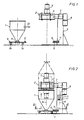
- the mixing device according to the invention will first be described generally with reference to FIGS. 1 and 2, the illustration in FIG. 2 in particular showing the overall structure or the overall arrangement of the mixing device.
- the mixing device contains a mixing container which essentially consists of a movable first container part 1 and a stationary container part 2.
- the first container part 1 is provided with a floor outlet 1a, and it is carried by a chassis which, in the exemplary embodiment illustrated, is designed in the form of a driving pallet 3 provided with wheels 3a and on which the first container part 1 is known per se and therefore not closer illustrated manner is releasably attached so that it can be lifted off from this range for connection to the second container part 2.
- the second container part 2 is equipped with mixing tools 4 known per se, which can be driven in rotation by a motor drive unit.
- the mixing device also contains a stationary holder 6, at the upper end of which the second container part 2 is stationary so that it is 180 ° about a horizontal axis of rotation 7 between an initial position (approximately corresponding to FIG. 2) in which the second container part 2 Forms cover of the mixing container, and a mixing position (indicated by dash-dotted lines in Fig. 2), in which the second container part 2 forms the bottom of the mixing container, can be pivoted with the aid of a pivot drive 8.
- a stationary holder 6 at the upper end of which the second container part 2 is stationary so that it is 180 ° about a horizontal axis of rotation 7 between an initial position (approximately corresponding to FIG. 2) in which the second container part 2 Forms cover of the mixing container, and a mixing position (indicated by dash-dotted lines in Fig. 2), in which the second container part 2 forms the bottom of the mixing container, can be pivoted with the aid of a pivot drive 8.
- a guide fork 9 is also fixed, which is intended for receiving the chassis (pallet 3) in the starting position (and also in the mixing position) of the mixing container.
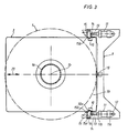
- two stop elements 10 are symmetrical on both sides of the vertical central axis 1b of the first container part 1 and on the end section 3b of the driving pallet 3 facing the guide fork 9, preferably welded on.
- a guide device which can be brought into clamping engagement with these stop elements 10 is provided on the guide fork 9 such that the driving pallet 3 together with the first container part 1 can be pulled into the starting position of the mixing container and locked there.
- the aforementioned pull-in device for the driving pallet 3 contains, on each side of the guide fork 9, pressure-medium-operated, preferably pneumatically actuated cylinder-piston units 11, these two cylinder-piston units 11 likewise being symmetrical on both sides of the vertical central axis 1b of the first container part 1 (and thus also the vertical mixing container axis determined thereby) are arranged.
- Each cylinder-piston unit 11 is assigned to a stop element 10 of the driving range 3 for a clamping engagement.
- each cylinder-piston unit 11 is pivotally supported at its one end 11a via a pivot pin 12 on the guide fork 9 and at its other end 11b via the free end of its piston rod 13 in an articulated manner (pivot pin 14) to a pivot lever 15, the one end 15a is rotatably mounted on the guide fork 9 via a pivot pin 16 and the other end 15b of which can be brought into clamping engagement with the associated stop element 10 of the driving range 3.
- each stop element 10 can be designed in the form of a stop block welded onto the driving pallet 3, and each stop block can be angular so that it has an engagement recess 10a for the associated pivot lever 15 or its end 15b.
- the pull-in device provided on the guide fork may also contain pull-in members operated in other ways, for example mechanical lever or spindle drives or electric pistons, instead of the pressure-medium-operated cylinder-piston units.
- this mixing device contains a correspondingly adapted control device, which is indicated at 17 in FIG. 2.
- this control device 17 With the help of this control device 17, the pivoting and mixing operation can be initiated and carried out in the desired manner.
- the guide fork 9 carries a limit switch (proximity switch) 18 which - as indicated by the dashed line 19 - is connected to the control device 17 in terms of control and by means of the fully in the guide fork 9 retracted driving pallet 3, that is to say by its end section 3b facing the guide fork 9, can be actuated.
- This design particularly favors fully automatic operation of the mixing device, ie if the driving range 3 which has been moved into the guide fork 9 together with the first container part 1 in the direction of arrow 20 (FIGS.
Landscapes
- Chemical & Material Sciences (AREA)
- Chemical Kinetics & Catalysis (AREA)
- Accessories For Mixers (AREA)
Description
- Die Erfindung bezieht sich auf eine Mischvorrichtung nach dem Oberbegriff des Anspruches 1.
- Mischvorrichtungen der vorausgesetzten Art sind in verschiedenen Ausführungsformen aus der Praxis bekannt, wobei die Mischvorrichtung in ihrer Grundform beispielsweise etwa gemäß DE-C-21 10 074 oder DE-A-34 26 159 ausgeführt sein kann. In der praxisgerechten Ausführung dieser bekannten Mischvorrichtungen wird der erste Behälterteil des Mischbehälters dann, wenn er nicht fest mit dem ersten Behälterteil verbunden ist, von einem Fahrgestell getragen, wobei er dann lösbar darauf befestigt ist. Dieser erste Behälterteil kann dadurch beispielsweise einerseits zwischen einer Befüllstation und den ortsfesten Teilen der Mischvorrichtung sowie andererseits zwischen diesem ortsfesten Teil der Mischvorrichtung und einer Verbraucherstation verfahren werden.
- Damit der mit einer Mischgutcharge befüllte erste Behälterteil in seine Ausgangsstellung unter den stationären zweiten Behälterteil gefahren und dort zur vertikalen Behälterachse ausgerichtet werden kann, ist an der ortsfesten Halterung der Mischvorrichtung eine Führungsgabel angeordnet, die das Fahrgestell in der Ausgangsstellung und Mischstellung des Mischbehälters aufnimmt.
- In der Praxis hat sich nun gezeigt, daß es trotz des Vorsehens der Führungsgabel oft sehr schwierig ist, das Fahrgestell mitsamt dem gefüllten ersten Behälterteil in der gewünschten Weise in die Ausgangsstellung für den Mischbehälter einzufahren. Dieser Einfahrvorgang muß, insbesondere bei größeren Behältertypen, häufig wiederholt werden, bis das Fahrgestell mit dem ersten Behälterteil exakt in der Führungsgabel und damit unter dem stationären zweiten Behälterteil steht.
- Der Erfindung liegt daher die Aufgabe zugrunde, eine Mischvorrichtung der im Oberbegriff des Anspruches 1 vorausgesetzten Art zu schaffen, bei der durch relativ einfache bauliche Maßnahmen zuverlässig dafür gesorgt ist, daß der erste Behälterteil rasch und genau zum zweiten Behälterteil ausgerichtet in die Ausgangsstellung fahrbar ist.
- Diese Aufgabe wird erfindungsgemäß durch die im Kennzeichen des Anspruches 1 angegebenen Merkmale gelöst, wobei zweckmäßige Ausgestaltungen und Weiterbildungen der Erfindung Gegenstand der Unteransprüche sind.
- Da bei der erfindungsgemäßen Ausführung der Mischvorrichtung einerseits am Fahrgestell wenigstens ein Anschlagelement befestigt und andererseits an der Führungsgabel eine mit dem Anschlagelement in Eingriff bringbare Einzugsvorrichtung vorgesehen ist, kann auf äußerst zuverlässige Weise dafür gesorgt werden, daß das Fahrgestell mitsamt dem davon getragenen ersten Behälterteil in die Ausgangsstellung des Mischbehälters eingezogen und arretiert wird, was aufgrund der Anordnung und Ausbildung der Führungsgabel sowie der passend zu dieser Führungsgabel entsprechend der Ausgangsstellung des Mischbehälters vorgesehenen Ausführung des Fahrgestelles sehr rasch geschehen kann. Wenn bei dieser erfindungsgemäßen Ausführung das Fahrgestell in die Führungsgabel eingefahren wird, dann kommt die Einzugsvorrichtung mit dem Anschlagelement (vorzugsweise mit wenigstens zwei Anschlagelementen) des Fahrgestells in Spanneingriff, so daß durch die Aktivierung der Einzugsvorrichtung das Fahrgestell über das Anschlagelement ergriffen und sofort beim ersten Einfahren exakt in seine Endposition eingezogen und festgehalten wird. Diese Endposition des Fahrgestells in der Führungsgabel stimmt dann mit der Stellung des ersten Behälterteiles überein, in der letzterer in der Ausgangsstellung des Mischbehälters genau unter dem zweiten Behälterteil ausgerichtet ist.
- Ein weiterer Vorteil dieser erfindungsgemäßen Ausführung der Mischvorrichtung ergibt sich durch die Tatsache, daß das Fahrgestell während des Mischvorganges sicher in der Führungsgabel gehalten und arretiert ist, wodurch nach Beendigung des Mischvorganges und Rückkehr des Mischbehälters in seine Ausgangsstellung ein exaktes Wiederaufsetzen des ersten Behälterteiles auf das Fahrgestell gewährleistet ist.
- Die Erfindung sei nachfolgend anhand eines in der Zeichnung veranschaulichten Ausführungsbeispieles näher beschrieben. In dieser weitgehend schematisch gehaltenen Zeichnung zeigen
- Fig. 1 eine Seitenansicht der Mischvorrichtung beim Einfahren des ersten Mischbehälterteiles in die Ausgangsstellung;
- Fig. 2 eine gleiche Seitenansicht wie in Fig. 1, jedoch bei vertikalachsig zueinander ausgerichteten Behälterteilen (Ausgangsstellung des Mischbehälters) vor ihrem Zusammenkuppeln, wobei das Fahrgestell in die Führungsgabel eingezogen ist;
- Fig. 3 eine Aufsicht auf das Fahrgestell und die Führungsgabel etwa entsprechend der Linie III - III in Fig. 2.
- Die erfindungsgemäße Mischvorrichtung sei zunächst allgemein anhand der Fig. 1 und 2 beschrieben, wobei vor allem die Darstellung in Fig. 2 den Gesamtaufbau bzw. die Gesamtzusammenordnung der Mischvorrichtung erkennen läßt.
- Die Mischvorrichtung enthält einen Mischbehälter, der im wesentlichen aus einem verfahrbaren ersten Behälterteil 1 und einem stationären Behälterteil 2 besteht. Dabei ist der erste Behälterteil 1 mit einem Bodenauslauf 1a versehen, und er wird von einem Fahrgestell getragen, das im veranschaulichten Ausführungsbeispiel in Form einer mit Rädern 3a versehenen Fahrpalette 3 ausgeführt ist und auf dem der erste Behälterteil 1 in an sich bekannter und daher nicht näher veranschaulichter Weise lösbar befestigt ist, so daß er für eine Verbindung mit dem zweiten Behälterteil 2 von dieser Fahrpalette abgehoben werden kann.
- Der zweite Behälterteil 2 ist mit an sich bekannten Mischwerkzeugen 4 ausgestattet, die durch eine Motorantriebseinheit drehend angetrieben werden können.
- Die Mischvorrichtung enthält ferner eine ortsfeste Halterung 6, an deren oberen Ende der zweite Behälterteil 2 stationär derart gehaltert ist, daß er um 180° um eine horizontale Drehachse 7 zwischen einer Ausgangsstellung (etwa entsprechend Fig. 2), in der der zweite Behältertei 2 den Deckel des Mischbehälters bildet, und einer Mischstellung (in Fig. 2 strichpunktiert angedeutet), in der der zweite Behälterteil 2 den Boden des Mischbehälters bildet, mit Hilfe eines Schwenkantriebes 8 geschwenkt werden kann.
- An der ortsfesten Halterung 6 ist ferner eine Führungsgabel 9 fest angeordnet, die für die Aufnahme des Fahrgestelles (Fahrpalette 3) in der Ausgangsstellung (und auch in der Mischstellung) des Mischbehälters bestimmt ist.
- Wie insbesondere in Fig. 3 in der Aufsicht auf die Fahrpalette 3 und die Führungsgabel 9 veranschaulicht ist, sind im vorliegenden Beispiel auf der Oberseite der Fahrpalette 3 zwei Anschlagelemente 10 symmetrisch zu beiden Seiten der vertikalen Mittelachse 1b des ersten Behälterteiles 1 sowie an dem der Führungsgabel 9 zugewandten Endabschnitt 3b der Fahrpalette 3 befestigt, vorzugsweise angeschweißt. An der Führungsgabel 9 ist demgegenüber eine mit diesen Anschlagelementen 10 in Spanneingriff bringbare Einzugsvorrichtung derart vorgesehen, daß die Fahrpalette 3 mitsamt dem ersten Behälterteil 1 in die Ausgangsstellung des Mischbehälters gezogen und dort arretiert werden kann.
- Die zuvor erwähnte Einzugsvorrichtung für die Fahrpalette 3 enthält auf jeder Seite der Führungsgabel 9 angebrachte, druckmittelbetriebene, vorzugsweise pneumatisch betätigbare Zylinder-Kolben-Einheiten 11, wobei diese beiden Zylinder-Kolben-Einheiten 11 ebenfalls symmetrisch zu beiden Seiten der vertikalen Mittelachse 1b des ersten Behälterteiles 1 (und somit auch der dadurch bestimmten vertikalen Mischbehälterachse) angeordnet sind. Jede Zylinder-Kolben-Einheit 11 ist dabei für einen Spanneingriff einem Anschlagelement 10 der Fahrpalette 3 zugeordnet.
- Im einzelnen ist jede Zylinder-Kolben-Einheit 11 mit ihrem einen Ende 11a schwenkbar über einen Schwenkzapfen 12 an der Führungsgabel 9 gehaltert und an ihrem anderen Ende 11b über das freie Ende ihrer Kolbenstange 13 gelenkig ( Gelenkzapfen 14) mit einem Schwenkhebel 15 verbunden, dessen eines Ende 15a über einen Schwenkzapfen 16 an der Führungsgabel 9 drehbar gelagert ist und dessen anderes Ende 15b mit dem zugehörigen Anschlagelement 10 der Fahrpalette 3 in Spanneingriff gebracht werden kann.
- Wie in Fig. 3 gut zu erkennen ist, kann jedes Anschlagelement 10 in Form eines auf der Fahrpalette 3 aufgeschweißten Anschlagklotzes ausgebildet sein, und jeder Anschlagklotz kann dabei winkelförmig ausgeführt sein, so daß er eine Eingriffsausnehmung 10a für den zugehörigen Schwenkhebel 15 bzw. dessen Ende 15b aufweist.
- Während bei dieser bisher beschriebenen Ausführungsform zwei Anschlagelemente 10 mit diesen zugeordneten Zylinder-Kolben-Einheiten 11 vorgesehen sind, kann bei einer besonders einfachen Ausführung, insbesondere kleineren Behältertypen, auch bereits ein einziges Anschlagelement - bei entsprechend symmetrischer Anbringung - ausreichend sein, und es versteht sich dabei ferner von selbst, daß die an der Führungsgabel vorgesehene Einzugsvorrichtung anstelle der druckmittelbetriebenen Zylinder-Kolben-Einheiten auch anderweitig betriebene Einzugsorgane, beispielsweise mechanische Hebel- oder Spindelantriebe oder Elektrokolben, enthalten kann.
- Bei einer Mischvorrichtung der erläuterten Art soll der Mischvorgang vielfach auch teil- oder vollautomatisch gesteuert werden können, wozu diese Mischvorrichtung eine entsprechend angepaßte Steuereinrichtung enthält, die in Fig. 2 bei 17 angedeutet ist. Mit Hilfe dieser Steuereinrichtung 17 kann der Schwenk- und Mischbetrieb in gewünschter Weise eingeleitet und durchgeführt werden.
- Im Zusammenhang mit einer solchen Steuereinrichtung 17 kann es bei der Mischvorrichtung ferner besonders vorteilhaft sein, wenn die Führungsgabel 9 einen Endschalter (Näherungsschalter) 18 trägt, der - wie durch die gestrichelte Linie 19 angedeutet - mit der Steuereinrichtung 17 steuerungsmäßig verbunden und durch die voll in die Führungsgabel 9 eingefahrene Fahrpalette 3, d. h. durch deren der Führungsgabel 9 zugewandten Endabschnitt 3b, betätigbar ist. Diese Ausbildung begünstigt besonders einen vollautomatischen Betrieb der Mischvorrichtung, d. h. wenn die in Richtung des Pfeiles 20 (Fig. 1 und 3) mitsamt dem ersten Behälterteil 1 in die Führungsgabel 9 eingefahrene Fahrpalette 3 voll eingezogen und arretiert ist, dann schaltet sie den Endschalter 18 in der Weise, daß dadurch der gesamte Mischvorgang - beginnend mit dem Verspannen der beiden Behälterteile 1 und 2 und dem Schwenken des Mischbehälters um die horizontale Achse 7 - eingeleitet und vollautomatisch durchgeführt werden kann.
Claims (6)
dadurch gekennzeichnet,
Applications Claiming Priority (2)
| Application Number | Priority Date | Filing Date | Title |
|---|---|---|---|
| DE8814068U DE8814068U1 (de) | 1988-11-10 | 1988-11-10 | Mischvorrichtung |
| DE8814068U | 1988-11-10 |
Publications (2)
| Publication Number | Publication Date |
|---|---|
| EP0367950A1 EP0367950A1 (de) | 1990-05-16 |
| EP0367950B1 true EP0367950B1 (de) | 1992-04-15 |
Family
ID=6829724
Family Applications (1)
| Application Number | Title | Priority Date | Filing Date |
|---|---|---|---|
| EP89117116A Expired - Lifetime EP0367950B1 (de) | 1988-11-10 | 1989-09-15 | Mischvorrichtung |
Country Status (4)
| Country | Link |
|---|---|
| US (1) | US5123747A (de) |
| EP (1) | EP0367950B1 (de) |
| DE (2) | DE8814068U1 (de) |
| ES (1) | ES2031327T3 (de) |
Families Citing this family (21)
| Publication number | Priority date | Publication date | Assignee | Title |
|---|---|---|---|---|
| DE4002536C2 (de) * | 1990-01-29 | 2001-10-25 | Herfeld Gmbh & Co Kg Dr | Mischanlage |
| US5221174A (en) * | 1991-10-18 | 1993-06-22 | Valley Fabrication, Inc. | Field shuttle with end mounted lift |
| DE19708075C1 (de) * | 1997-02-28 | 1998-11-05 | Thyssen Industrie | Mischer für einen pulverförmigen, grießförmigen und/oder granulatförmigen Stoff |
| US5865538A (en) * | 1997-05-05 | 1999-02-02 | Readco Manufacturing, Inc. | Containerized batch mixer |
| US6062724A (en) * | 1999-01-22 | 2000-05-16 | Habicht; Helmut | Clamp for retaining a removable frame on a lifting apparatus for material handling equipment |
| US6966691B2 (en) * | 2000-04-28 | 2005-11-22 | Premark Feg L.L.C. | Mixer with pivotable bowl |
| US6991363B2 (en) * | 2000-04-28 | 2006-01-31 | Premark Feg L.L.C. | Mixer with pivotable bowl |
| US8251567B2 (en) * | 2000-04-28 | 2012-08-28 | Premark Feg L.L.C. | Mixer with pivotable bowl |
| US6331070B1 (en) * | 2000-10-30 | 2001-12-18 | Reliance Industries, Inc. | Process and apparatus for particle size reduction and homogeneous blending of ingredients in a fluidized change can mixer |
| US6802641B2 (en) * | 2002-12-19 | 2004-10-12 | Spraylat Corporation, Inc. | Invertible mixing system with angled blade assembly and method for mixing powders with such system |
| DE20309987U1 (de) | 2003-06-27 | 2003-08-28 | Sadaana, Hichem, 59846 Sundern | Mischer |
| DE602005009534D1 (de) * | 2004-05-07 | 2008-10-16 | Premark Feg Llc | Rührgerät mit schwenkbarer schüssel |
| US7325969B2 (en) * | 2004-07-08 | 2008-02-05 | Glatt Systemtechnik Gmbh | Container mixer |
| US7950843B2 (en) * | 2008-01-23 | 2011-05-31 | Premark Feg L.L.C. | Mixing machine and associated bowl support arrangement |
| US8182135B2 (en) * | 2009-01-22 | 2012-05-22 | Premark Feg L.L.C. | Mixing machine with bowl support |
| DE202009011685U1 (de) * | 2009-08-28 | 2009-12-03 | Schleinzer, Werner | Vorrichtung zur Verarbeitung von Lebensmitteln |
| EP2392212B1 (de) * | 2010-06-03 | 2013-04-24 | SANCASSIANO S.p.A. | Knetmaschine mit einer Vorrichtung zur Fixierung des Behälters |
| US9629503B2 (en) * | 2014-07-30 | 2017-04-25 | North American Robotics Corporation | Blending container for use with blending apparatus |
| US10624499B2 (en) | 2014-07-30 | 2020-04-21 | North American Robotics Corporation | Systems and methods for pressure control in automated blending devices |
| DE202016107397U1 (de) * | 2016-12-27 | 2018-03-28 | Zeppelin Systems Gmbh | Mischwerkzeug für einen Mischer und Mischer |
| DE202022106589U1 (de) | 2022-11-24 | 2024-02-27 | Zeppelin Systems Gmbh | Einzugsvorrichtung für einen Mischcontainer |
Family Cites Families (21)
| Publication number | Priority date | Publication date | Assignee | Title |
|---|---|---|---|---|
| DE1074011B (de) * | 1960-01-28 | Paul Vollrath Maschinenfabrik Köln | Auf Rollen gelagerter umlaufender offener Mischtrog mit einem exzentrisch zu der Trogachse angeordneten Ruhr werkzeug | |
| NL1600C (nl) * | 1912-10-25 | 1916-10-02 | Benier Gerardus Johannes | Deegkneedmachine |
| FR533171A (fr) * | 1921-03-31 | 1922-02-23 | Lussi & Stagg | Pétrin mécanique mobile à levier avec mouvement en hélice |
| US3137327A (en) * | 1961-01-09 | 1964-06-16 | Gen Machine Company Of New Jer | Loading and unloading system for blenders and the like |
| US3174728A (en) * | 1963-02-28 | 1965-03-23 | Patterson Ind Inc | Blending apparatus |
| US3571872A (en) * | 1968-07-30 | 1971-03-23 | La Salle Machine Tool | Pallet locating and clamping apparatus |
| NL162184C (nl) * | 1970-06-16 | 1980-04-15 | Langen & Zonen Bv | Inrichting voor rotatie-aandrijving van een transport- vat. |
| FR2108888B1 (de) * | 1970-10-16 | 1973-11-30 | Pechiney Ugine Kuhlmann | |
| US3696756A (en) * | 1971-02-01 | 1972-10-10 | Teledyne Mid America Corp | Car retaining cushioned latch mechanism |
| DE2110047C2 (de) * | 1971-03-03 | 1983-01-20 | Herfeld, Dipl.-Volksw. Dr., Friedrich Walter Adolf, 5982 Neuenrade | Mischvorrichtung |
| IT1057323B (it) * | 1975-08-29 | 1982-03-10 | Gen Signal Corp | Apparecchiatura per manipolare e trattare materiale in contenitori di processo |
| US4372686A (en) * | 1981-05-20 | 1983-02-08 | Herfeld Friedrich W | Double-cone rotating mixer |
| DE3123362A1 (de) * | 1981-06-12 | 1982-12-30 | Herfeld, Friedrich Walter, Dr., 5982 Neuenrade | Mischvorrichtung |
| US4732258A (en) * | 1981-10-09 | 1988-03-22 | Burgess Jr Warren C | Vibratory feeding work station module and system |
| US4555211A (en) * | 1982-06-11 | 1985-11-26 | Metz Donald L | Truck locking device |
| DE3426159A1 (de) * | 1984-07-16 | 1986-01-23 | Herfeld, Friedrich Walter, Dr., 5982 Neuenrade | Mischvorrichtung |
| DE3433674A1 (de) * | 1984-09-13 | 1986-03-20 | Friedrich Walter Dr. 5982 Neuenrade Herfeld | Mischvorrichtung |
| US4757890A (en) * | 1985-04-19 | 1988-07-19 | Motoda Denshi Kogyo Kabushiki Kaisha | Tray positioning arrangement for delivery system |
| DE3543913A1 (de) * | 1985-12-12 | 1987-06-19 | Herfeld Friedrich W | Mischvorrichtung |
| JPH02503187A (ja) * | 1987-04-22 | 1990-10-04 | ハリス アンソニー マイクル | 貨物車の位置決め装置 |
| GB8808403D0 (en) | 1988-04-11 | 1988-05-11 | Ass Elect Ind | Extrusion process & apparatus |
-
1988
- 1988-11-10 DE DE8814068U patent/DE8814068U1/de not_active Expired
-
1989
- 1989-09-15 ES ES198989117116T patent/ES2031327T3/es not_active Expired - Lifetime
- 1989-09-15 DE DE8989117116T patent/DE58901176D1/de not_active Expired - Lifetime
- 1989-09-15 EP EP89117116A patent/EP0367950B1/de not_active Expired - Lifetime
- 1989-09-25 US US07/412,150 patent/US5123747A/en not_active Expired - Lifetime
Also Published As
| Publication number | Publication date |
|---|---|
| ES2031327T3 (es) | 1992-12-01 |
| DE8814068U1 (de) | 1989-01-05 |
| US5123747A (en) | 1992-06-23 |
| EP0367950A1 (de) | 1990-05-16 |
| DE58901176D1 (de) | 1992-05-21 |
Similar Documents
| Publication | Publication Date | Title |
|---|---|---|
| EP0367950B1 (de) | Mischvorrichtung | |
| EP0173180A1 (de) | Kipp- oder Hubkipp-Vorrichtung zum Entleeren von Behältern in Sammelbehälter, vorzugsweise Müllbehälter in den Sammelbehälter eines Müllfahrzeugs | |
| EP0365814A1 (de) | Verfahren und Vorrichtung zum Mischen von pulverförmigen bis körnigen Schüttgütern | |
| DE1134431B (de) | Verfahren zum Anbringen kleiner elektrischer Einzelteile, z. B. Widerstaende, Kondensatoren, Roehrenfassungen, Brueckendraehte u. dgl. auf einer mit OEffnungen versehenen Montage-platte und Vorrichtung zur Durchfuehrung dieses Verfahrens | |
| DE102019111950B4 (de) | Stapelbare Lagereinheit und Stapel aus Lagereinheiten | |
| DE2927142A1 (de) | Fadenwechseleinrichtung fuer stickmaschinen | |
| CH662295A5 (de) | Verfahren zum herausschneiden oder -trennen von teilen aus einer werkstuecktafel auf einer schneidpresse sowie schneidpresse zur durchfuehrung des verfahrens. | |
| DE3230051A1 (de) | Werkzeugmaschine mit automatischer werkzeugwechselvorrichtung | |
| DE2553466A1 (de) | Werkzeugmaschine mit auswechselbaren werkzeugtraegern | |
| DE3443378C2 (de) | Anordnung zur Palettenabgabe bzw. Palettenaufnahme an ein regalartiges bzw. aus einem regalartigen Gestell | |
| DE2411744A1 (de) | Presse zum pressverbinden eines mindestens teilweise drahtfoermigen teiles mit einem abschlussteil | |
| DE3127019A1 (de) | "vorrichtung fuer einen submast-hublader mit in fahrzeugrichtung laengsbeweglich gehaltenem batteriewagen" | |
| EP0648526B1 (de) | Mischvorrichtung | |
| DE20105903U1 (de) | Schneidemaschine zur Querbeschneidung von Gardinen- und Netzstoffen | |
| DE2031219A1 (de) | Werkzeug-Wechselvornchtung fur Werk zeugmaschmen | |
| EP0344635A1 (de) | Vorrichtung zum Verzurren von Containern | |
| DE3637204C2 (de) | ||
| DE4002536C2 (de) | Mischanlage | |
| DE2944102C2 (de) | Langholzträger | |
| DE102004001751B4 (de) | Farbzufuhrvorrichtung für Druckmaschinen | |
| EP0200962A2 (de) | Spritzgiesseinheit für eine Kunststoff-Spritzgiessmaschine | |
| DE3412427A1 (de) | Montageeinrichtung fuer axialsicherungen | |
| DE2603861B2 (de) | Anordnung bei einer Wickelvorrichtung für fadenförmiges Gut | |
| AT398854B (de) | Zwischenträgerstück | |
| DE2156379A1 (de) | Vorrichtung zum Einbauen von Filterkerzen in einen Behälter |
Legal Events
| Date | Code | Title | Description |
|---|---|---|---|
| PUAI | Public reference made under article 153(3) epc to a published international application that has entered the european phase |
Free format text: ORIGINAL CODE: 0009012 |
|
| AK | Designated contracting states |
Kind code of ref document: A1 Designated state(s): DE ES FR GB IT |
|
| 17P | Request for examination filed |
Effective date: 19901115 |
|
| 17Q | First examination report despatched |
Effective date: 19910826 |
|
| GRAA | (expected) grant |
Free format text: ORIGINAL CODE: 0009210 |
|
| ITF | It: translation for a ep patent filed | ||
| AK | Designated contracting states |
Kind code of ref document: B1 Designated state(s): DE ES FR GB IT |
|
| REF | Corresponds to: |
Ref document number: 58901176 Country of ref document: DE Date of ref document: 19920521 |
|
| GBT | Gb: translation of ep patent filed (gb section 77(6)(a)/1977) | ||
| ET | Fr: translation filed | ||
| REG | Reference to a national code |
Ref country code: ES Ref legal event code: FG2A Ref document number: 2031327 Country of ref document: ES Kind code of ref document: T3 |
|
| PLBE | No opposition filed within time limit |
Free format text: ORIGINAL CODE: 0009261 |
|
| STAA | Information on the status of an ep patent application or granted ep patent |
Free format text: STATUS: NO OPPOSITION FILED WITHIN TIME LIMIT |
|
| 26N | No opposition filed | ||
| REG | Reference to a national code |
Ref country code: GB Ref legal event code: IF02 |
|
| PGFP | Annual fee paid to national office [announced via postgrant information from national office to epo] |
Ref country code: IT Payment date: 20080925 Year of fee payment: 20 Ref country code: FR Payment date: 20080912 Year of fee payment: 20 |
|
| PGFP | Annual fee paid to national office [announced via postgrant information from national office to epo] |
Ref country code: GB Payment date: 20080918 Year of fee payment: 20 |
|
| PGFP | Annual fee paid to national office [announced via postgrant information from national office to epo] |
Ref country code: DE Payment date: 20080919 Year of fee payment: 20 |
|
| PGFP | Annual fee paid to national office [announced via postgrant information from national office to epo] |
Ref country code: ES Payment date: 20080929 Year of fee payment: 20 |
|
| REG | Reference to a national code |
Ref country code: GB Ref legal event code: PE20 Expiry date: 20090914 |
|
| REG | Reference to a national code |
Ref country code: ES Ref legal event code: FD2A Effective date: 20090916 |
|
| PG25 | Lapsed in a contracting state [announced via postgrant information from national office to epo] |
Ref country code: GB Free format text: LAPSE BECAUSE OF EXPIRATION OF PROTECTION Effective date: 20090914 |
|
| PG25 | Lapsed in a contracting state [announced via postgrant information from national office to epo] |
Ref country code: ES Free format text: LAPSE BECAUSE OF EXPIRATION OF PROTECTION Effective date: 20090916 |