EP0367970A1 - Appareil de lubrification pour le chapeau marchant d'une carde - Google Patents
Appareil de lubrification pour le chapeau marchant d'une carde Download PDFInfo
- Publication number
- EP0367970A1 EP0367970A1 EP89117956A EP89117956A EP0367970A1 EP 0367970 A1 EP0367970 A1 EP 0367970A1 EP 89117956 A EP89117956 A EP 89117956A EP 89117956 A EP89117956 A EP 89117956A EP 0367970 A1 EP0367970 A1 EP 0367970A1
- Authority
- EP
- European Patent Office
- Prior art keywords
- lubricating device
- sliding surfaces
- housing
- lubricant
- brush
- Prior art date
- Legal status (The legal status is an assumption and is not a legal conclusion. Google has not performed a legal analysis and makes no representation as to the accuracy of the status listed.)
- Withdrawn
Links
Images


Classifications
-
- D—TEXTILES; PAPER
- D01—NATURAL OR MAN-MADE THREADS OR FIBRES; SPINNING
- D01G—PRELIMINARY TREATMENT OF FIBRES, e.g. FOR SPINNING
- D01G15/00—Carding machines or accessories; Card clothing; Burr-crushing or removing arrangements associated with carding or other preliminary-treatment machines
- D01G15/02—Carding machines
- D01G15/12—Details
- D01G15/14—Constructional features of carding elements, e.g. for facilitating attachment of card clothing
- D01G15/24—Flats or like members
Definitions
- the present invention relates to a lubricating device for the revolving cover arrangement of a card, in which the revolving cover is moved in a loop by two chains arranged on the end faces of the card and engaging at the ends of the revolving cover and are guided at least in the region of the spool by stationary guides along which Slide the sliding surfaces of the covers.
- the wear of the guides or the sliding surfaces can include can be significantly reduced by adding lubricant.
- the supply of lubricants is extremely difficult, however, because the amount of lubricant dosed per unit of time must be determined very precisely in order to avoid excess lubricant on the one hand, and lack of lubricant on the other and wear and tear of the guide and the sliding surfaces. Unnecessary lubricant is undesirable for several reasons. On the one hand, there is a risk of contaminating the very fine fiber pile, on the other hand, lubricants tend to bind dust and flying fibers, which can ultimately lead to the traveling cover arrangement becoming stuck or overloaded.
- the object of the present invention is to provide a lubricating device which works maintenance-free and reliably over a long period of time in the case of inexpensive manufacture, above all in the sense that the metered amount of lubricant per unit time can be kept within predetermined limits over a long period of time.
- the invention provides that at least one lubricant container is provided on both sides of the revolving cover arrangement; that for the metered lubrication of the sliding surfaces, a rotatable transmission element associated with the respective lubricant container comes into contact with both the lubricant and the sliding surfaces; and that a gear wheel driving the transmission element is provided which is driven by the respective chain.
- each transmission system consisting of a transmission element and a gearwheel assigned to it.
- the lubricant is in the form of graphite rods, in particular graphite rods bound with a binder, for example wax.
- the hardness of the graphite rods can be selected by carefully selecting the binder so that only very small quantities are removed by the transfer element and transferred to the sliding surfaces.
- the transmission element is preferably a rotatably mounted brush, the bristle tips of which remove the graphite from the graphite rod and transfer it to the sliding surfaces.
- This design has the particular advantage that the speed of rotation of the brush can be selected so that the bristle tips transfer the ablated graphite to the sliding surfaces in minimal quantities with only one type of dab, i.e. there is no great difference between the peripheral speed of the bristle tips and the speed of movement of the sliding surfaces past the brush.
- the toothed wheel can be fastened to the axis of rotation of the brush coaxially with the latter.
- This version is very easy to implement, and the gear and brush can be made with comparable diameters, so that the desired speed can be adjusted.
- the surface speed of the brush is selected to be somewhat lower than the speed of movement of the sliding surfaces past it and is preferably in the range from 50 to 95% and in particular approximately 90% of this speed of movement of the sliding surfaces.
- the different speeds result in a certain slippage between the bristle tips and the sliding surfaces, which is favorable for the lubrication of the sliding surfaces.
- the bristle tips remove excess lubricant from the sliding surfaces, so that the lubrication is uniform.
- the desired slip can be achieved in that the sliding surfaces come into contact with the brush radially within the pitch circle of the gear wheel.
- a particularly preferred embodiment is characterized in that the container has a tubular part that is used to hold the graphite rod is designed that the tubular part can be closed with a stopper and that a helical compression spring is arranged between the stopper and the graphite rod for prestressing it in the direction of the brush, the helical compression spring being designed such that the spring preload remains at least substantially constant over its spring travel .
- the container can be a cylindrical cartridge containing the graphite rod under spring pressure, which can be connected to a tubular part of the lubrication device via a quick-release fastener, for example a bayonet fastener. This allows the graphite rod to be replaced very quickly.
- the tubular part for receiving the brush and its axis of rotation is preferably fork-shaped. This design is very easy to implement and provides a reliable mounting of both the axis of rotation and the brush, and the axis of rotation is mounted or held at two spaced locations in the individual legs of the fork.
- the articulated axes of the chain are preferably hollow, so that they extend at least on one side beyond the chain links and are fastened to the traveling covers by screws running through the articulated axes, the gearwheel with the parts of the articulated axles extending beyond the chain links or comes into contact with the sockets mounted on these.
- the invention is not restricted to the use of graphite rods as lubricants.
- the use of oil as a lubricant is also possible and in this case the transmission element is a wheel which is rotatably mounted within the housing containing the oil; and at least one element is provided which delimits the surface of the transmission element and the thickness of the oil film carried by it.
- the organ is preferably formed by a role.
- the sealing lips according to claim 18 are particularly important because they prevent not only an undesirable escape of oil, but also the contamination of the oil by dust and the like.
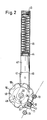
- FIG. 1 and 5 show side views of the traveling cover arrangement of a card, the embodiment according to FIG. 1 representing a lubrication device with graphite as a lubricant and that according to FIG. 5 a lubrication device with oil as a lubricant.
- revolving lids 11 there are a large number of revolving lids 11 (only a few of which are shown) which extend in the direction perpendicular to the plane of the drawing in FIGS. 1 and 5 over substantially the entire width of the card.
- Each revolving cover is attached at its two ends to respective circumferential chains 12, of which only one chain is shown in FIGS. 1 and 5.
- the revolving covers are over Screw bolts, which pass through the hollow joint axes between the individual chains, are fastened to the chains 12.
- Each revolving cover carries on its outer surface 15 a needle set 16 which can only be seen in FIGS. 3, 4, 7 and 8, but not in FIGS. 1 and 5, during the orbital movement of the chains and the revolving covers in the direction of the arrow 17 these needle sets pass corresponding needle sets of the reel 18, which rotates in the direction of the arrow 19.
- the dashed line 21 indicates the path of the geometric axes of the hinge pins 13 of the chains 12 during the orbital movement.
- the circular region 22 of this movement path 21 between the two deflection wheels 23, 24 must be precisely specified so that the needle sets of the revolving cover maintain the desired distance from the needle sets of the drum. This is achieved by circular guides on both sides of the card, the guide 25 being indicated only schematically in FIGS. 1 and 5.
- each revolving cover has two outer sliding surfaces 26, 27 at each end which slide along the guide 25.
- each revolving cover also has two inner sliding surfaces 28, 29 on the inner ends of the webs 31, 32, which slide in other areas of the orbit along static guides 33, which are only shown in regions in FIGS. 5 and 1. Since the inner sliding surfaces 28, 29 are less stressed than the outer sliding surfaces 26, 27, they are made somewhat narrower, which can be seen in particular from a comparison of FIGS. 3 and 4 or 7 and 8.
- each revolving cover has a longitudinal rib 34 which extends over its entire width.
- each chain is deflected via two toothed wheels 23 and 24, which are located in the immediate area of the reel.
- the orbital movement of the chains in the predetermined loop is also determined by two further deflection wheels 35, 36.
- the chain on the other side of the card is also guided over four deflection wheels arranged in the same way.
- two opposite wheels i.e. a deflection wheel on the left side of the card and a deflection wheel on the right side of the card, driven synchronously by means of a continuous shaft (not shown), so that the chain movements are synchronized with each other and the revolving cover is always parallel to the axis of rotation of the reel.
- the fact that either the two outer sliding surfaces or the two inner sliding surfaces always come to rest on a guide at each end of each revolving cover ensures that the longitudinal ribs 34 of the revolving cover are always perpendicular to the local movement path.
- FIG. 2 shows an enlarged view of the lubrication device II of FIG. 1.
- FIG. 1 shows three further such lubrication devices, the lubrication device identified by 37 being identical to the lubrication device II, but mounted in a different position.
- the lubrication device marked with 38 is designed in accordance with the lubrication device II, but dimensioned somewhat smaller, since it is responsible for the lubrication of the inner sliding surfaces of the revolving cover.
- the lubrication device identified by 39 is identical to the lubrication device 38 and only shows an alternative position thereof.
- the lubricating device II consists of a tubular part 41 in which a tubular extension 42 is permanently fixed, for example by welding.
- the tubular extension 42 is closed at its upper end with a screw plug 43 and contains a graphite rod 44, which is pressed down by means of a helical compression spring 45, which is located between the screw plug 43 and one end of the graphite rod 44 and is against the screw plug 43 supports.
- the tubular part is provided with two tabs 46 and 47, which are used for attachment to the card frame.
- the lower end of the tubular member 41 49 is bifurcated into two legs 48, over which the central longitudinal axis of the tubular member and the tubular extension ⁇ form an obtuse angle of about 150 o.
- the two legs 48, 49 serve to support an axis of rotation 51 with which a circular brush 52 with bristle tips 53 is fastened in a rotationally fixed manner between the legs 48, 49.
- the axis of rotation 51 is extended at one end beyond the end face of the associated leg 49 and carries a gear 54 there, which is fastened in a rotationally fixed manner to the axis by a corresponding positive arrangement.
- the axis of rotation itself is secured against axial displacement out of the legs 48, 49 by means of two retaining rings 55 and 56, which are seated in corresponding circumferential grooves of the axis of rotation.
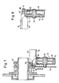
- the gear wheel 54 has recesses 58 on its outer circumference, the recesses 58 being arranged on a pitch circle 59 with a distance which corresponds to the linear distance between the hinge pins 13 of the chain.
- the deflection wheel 23 additionally shows the deflection wheel 23, which is rotatably supported by a tubular axle stub 62 of the card frame 60 by means of a corresponding bearing 61.
- the deflection wheel 23 also has recesses 63 which are arranged at a distance from the pivot pins 13 of the chains.
- each hinge pin is hollow and is fastened to the end 64 of a revolving cover 11 by means of a continuous screw pin 14.
- This attachment is such that two cylindrical bushes 65 and 66 are rotatably mounted on the actual hinge pin, the chain links 67, 68 being arranged between the two cylinder bushes 65 and 66.
- the cylinder sleeves 65, 66 engage in the recesses 63 of the deflection wheel 23 and the sleeve 65 also serves to drive the gear 54.
- FIG. 4 shows how the smaller lubrication device 38 is used to lubricate the inner sliding surfaces 28, 29. Since the arrangement is very similar to that of FIG. 3 and the only differences in the dimensions (diameter and length of the tubular part and width of the brush) can be determined, the same reference numerals have been used for the illustration of FIG. 4 as for 3, and the mode of operation of the embodiment according to FIG. 4 is to be understood in accordance with the description of FIG. 3.
- the lubrication device 71 is responsible for the lubrication of the outer sliding surfaces
- the lubrication device 72 is responsible for the lubrication of the inner sliding surfaces.
- 6 and 7 show the interaction of the lubricating device 71 with the outer sliding surfaces
- FIG. 8 shows how the lubricating device 72 interacts with the inner sliding surfaces.
- the lubrication devices 71, 72 are constructed in a very similar way. The only difference actually lies in the design of the transmission element 73, which is shown in FIG The outer circumference is much narrower than in the embodiment according to FIG. 7, just to take into account the different widths of the inner and outer sliding surfaces.
- the lubrication devices 71, 72 have an approximately U-shaped housing 75, which is identical in both cases. These housings contain oil as a lubricant, the surface of the oil being indicated at 76 and 77 in FIG. 5.
- the level of the oil level can be kept constant by any type of automatic refill system.
- the housing 75 can also consist entirely or partially of transparent material, so that a visual check of the oil level is possible. Due to the very small amount of oil used, it is also conceivable to refill the oil by hand from time to time.
- the housings are mounted in operation so that the oil contained therein cannot flow out through the open end of the housing.
- the housing itself is rotatably attached to the card frame via an axis of rotation 78 and is pretensioned in the direction of the revolving cover by means of a spring-loaded fastening device 49, which acts on a tab 81 on the other side of the housing from the axis of rotation 78, so that the surface of the cylinder shown here Transmission wheel is biased against the inner sliding surfaces or outer sliding surfaces of the revolving cover.
- the cylindrical surface of the transmission wheel can also be curved. The lubricant is then distributed naturally along the sliding surfaces due to the sliding movement on the static guides.
- the fastening device 79 can also be pivoted to the right into a position 79.1. In this position, the fastening of the housing is unlocked so that the housing 75 can be folded down and refilled or cleaned.
- a small roller 82 is also rotatably mounted in the housing and in such a way that its axis of rotation is parallel to the axis of rotation of the transmission wheel.
- the surface of the roller 82 is connected to the surface of the transmission wheel and ensures that only a very fine oil film is present on the outer surface of the transmission wheel, so that the metering of the lubricant onto the sliding surfaces is ensured in very small amounts.
- the roller 82 could also be replaced by a scraper.
- a cap 83 made of plastic is placed on the open side of the housing both in FIG. 7 and in the embodiment according to FIGS. 6 and 8, which cap is held on the housing by appropriately designed snap devices. As can be seen from FIG.
- this cap has sealing lips 85 on the side of the wheel, which on the one hand prevent oil from escaping at this point and on the other hand also prevent dust and the like from penetrating into the lubricant container or into the housing 75.
- the cap also has sealing lips 87, 88 which bear against the outer surface of the transmission wheel and also prevent the entry of dust and dirt here.
- the gear wheel is driven by the chain, but here by the cylinder bushes 66 and not by the cylinder bushes 65, and in turn drives the transmission wheel via the axis of rotation 51.
- the preload of the spring 80 ensures that the surface of the wheel with this very thin oil film always presses against the sliding surfaces with at least substantially constant pressure, so that an even oil transfer takes place, even if the sliding surfaces themselves are not affected by different signs of wear or tolerances come to lie exactly in the same place opposite the lubrication device.
- Such a bias is not necessary in the embodiment of FIGS. 1 to 4, since here the bristles themselves have a certain resilient effect and thus compensate for small differences in distance.
Landscapes
- Engineering & Computer Science (AREA)
- Textile Engineering (AREA)
- General Details Of Gearings (AREA)
- Preliminary Treatment Of Fibers (AREA)
Applications Claiming Priority (2)
| Application Number | Priority Date | Filing Date | Title |
|---|---|---|---|
| DE3834041A DE3834041A1 (de) | 1988-10-06 | 1988-10-06 | Schmiervorrichtung fuer die wanderdeckelanordnung einer karde |
| DE3834041 | 1988-10-06 |
Publications (1)
| Publication Number | Publication Date |
|---|---|
| EP0367970A1 true EP0367970A1 (fr) | 1990-05-16 |
Family
ID=6364532
Family Applications (1)
| Application Number | Title | Priority Date | Filing Date |
|---|---|---|---|
| EP89117956A Withdrawn EP0367970A1 (fr) | 1988-10-06 | 1989-09-28 | Appareil de lubrification pour le chapeau marchant d'une carde |
Country Status (4)
| Country | Link |
|---|---|
| US (1) | US4991262A (fr) |
| EP (1) | EP0367970A1 (fr) |
| JP (1) | JPH02145817A (fr) |
| DE (1) | DE3834041A1 (fr) |
Cited By (1)
| Publication number | Priority date | Publication date | Assignee | Title |
|---|---|---|---|---|
| EP0633332A1 (fr) * | 1993-07-06 | 1995-01-11 | Maschinenfabrik Rieter Ag | Appareil de lubrification pour barres de chapeaux d'une machine de cardage à chapeaux mobiles |
Families Citing this family (3)
| Publication number | Priority date | Publication date | Assignee | Title |
|---|---|---|---|---|
| DE4108921C2 (de) * | 1991-03-19 | 2001-03-01 | Truetzschler Gmbh & Co Kg | Vorrichtung an einer Karde mit wanderndem Deckel aus mit Garnitur versehenen Deckelstäben |
| AU2183397A (en) * | 1996-12-30 | 1998-07-31 | Vladimir Vladimirovich Shapovalov | Lubricant applied to a friction surface and apparatus for application thereof |
| US10900559B2 (en) * | 2018-05-31 | 2021-01-26 | James Zaguroli, Jr. | Automatic lubrication arrangement for a hoist |
Citations (2)
| Publication number | Priority date | Publication date | Assignee | Title |
|---|---|---|---|---|
| GB739967A (en) * | 1952-01-14 | 1955-11-02 | William Walker Jarrell | Automatic chain lubricator |
| GB1315371A (en) * | 1970-03-12 | 1973-05-02 | Tmm Research Ltd | Carding machine lubrication |
Family Cites Families (26)
| Publication number | Priority date | Publication date | Assignee | Title |
|---|---|---|---|---|
| US276987A (en) * | 1883-05-01 | Herman winter | ||
| DE274749C (fr) * | ||||
| US837774A (en) * | 1906-05-02 | 1906-12-04 | Frank Sides Baird | Wheel-flange oiler. |
| US1075941A (en) * | 1912-03-25 | 1913-10-14 | John M Reed | Belt-dressing applier. |
| US1192762A (en) * | 1915-05-13 | 1916-07-25 | Link Belt Co | Device for lubricating chains. |
| DE376423C (de) * | 1920-10-10 | 1923-05-28 | Aeg | Anordnung zum Schmieren von Kontakten |
| DE413251C (de) * | 1924-01-22 | 1925-05-11 | Bbc Brown Boveri & Cie | Vorrichtung zur Kontaktschmierung bei elektrischen Schaltapparaten |
| US1687688A (en) * | 1927-05-20 | 1928-10-16 | Morse Chain Co | Mechanical lubricator for chains |
| FR703805A (fr) * | 1930-02-17 | 1931-05-06 | Vaw Ver Aluminium Werke Ag | Procédé pour l'obtention de bons contacts avec des éléments conducteurs du courant, en aluminium ou ses alliages |
| US1914093A (en) * | 1932-03-24 | 1933-06-13 | Charles R Adams | Chain oiler |
| DE628898C (de) * | 1934-08-15 | 1936-04-18 | Stotz Kontakt Gmbh | Elektrischer Drehschalter mit Schmierung der Kontaktbahn |
| DE635250C (de) * | 1934-08-15 | 1936-09-14 | Stotz Kontakt Gmbh | Elektrischer Drehschalter mit Schmierung der Kontaktbahn |
| DE686840C (de) * | 1935-05-14 | 1940-01-17 | Max Purrmann | ngen mit Schmutzabstreicher fuer den bewegten Schaltkontakt |
| US2558370A (en) * | 1947-06-26 | 1951-06-26 | Charles R Miller | Automatic oiler for slat conveyers |
| US2541301A (en) * | 1948-07-22 | 1951-02-13 | Keenline Equipment Corp | Roller lubricator for the surface of conveyer belts |
| US2589582A (en) * | 1949-08-12 | 1952-03-18 | Strughold Peter | Lubricant stick |
| US2548739A (en) * | 1949-12-23 | 1951-04-10 | Peck S Products Company | Apparatus for applying lubricant to the surface of an endless conveyer |
| DE968748C (de) * | 1952-12-06 | 1958-03-27 | Erboe Maschb Erley & Boenninge | Schmiervorrichtung fuer von Laschenketten gezogene endlose Foerderer, insbesondere Stahlgliederbaender |
| DE1695609U (de) * | 1955-01-27 | 1955-03-31 | Voigt & Haeffner Ag | Vorrichtung zur kontaktschmierung bei schalterri mit scheibenfoermigen kontakten, insbesondere paketschaltern. |
| GB874102A (en) * | 1958-10-23 | 1961-08-02 | Allen Tool & Engineering Ltd | Improvements in or relating to holders for consumable elements |
| DE2037134C3 (de) * | 1969-09-24 | 1981-07-30 | VEB Transformatorenwerk Karl Liebknecht, DDR 1160 Berlin | Anordnung zur Schmierung von Gleitkontakten |
| US4127491A (en) * | 1976-07-23 | 1978-11-28 | Michael Ebert | Hybrid lubricant including halocarbon oil |
| US4159046A (en) * | 1977-08-29 | 1979-06-26 | C. L. Frost & Son, Inc. | Chain lubrication apparatus and method |
| DE2816900A1 (de) * | 1978-04-19 | 1979-10-25 | Wolters Peter Fa | Karde mit wanderndem deckel |
| US4619345A (en) * | 1985-01-22 | 1986-10-28 | Mary Rands | Flexible lubricant applicator |
| US4901820A (en) * | 1988-09-28 | 1990-02-20 | International Business Machines Corporation | Gold tab lubrication |
-
1988
- 1988-10-06 DE DE3834041A patent/DE3834041A1/de not_active Withdrawn
-
1989
- 1989-09-28 EP EP89117956A patent/EP0367970A1/fr not_active Withdrawn
- 1989-10-06 US US07/417,895 patent/US4991262A/en not_active Expired - Fee Related
- 1989-10-06 JP JP1260324A patent/JPH02145817A/ja active Pending
Patent Citations (2)
| Publication number | Priority date | Publication date | Assignee | Title |
|---|---|---|---|---|
| GB739967A (en) * | 1952-01-14 | 1955-11-02 | William Walker Jarrell | Automatic chain lubricator |
| GB1315371A (en) * | 1970-03-12 | 1973-05-02 | Tmm Research Ltd | Carding machine lubrication |
Cited By (1)
| Publication number | Priority date | Publication date | Assignee | Title |
|---|---|---|---|---|
| EP0633332A1 (fr) * | 1993-07-06 | 1995-01-11 | Maschinenfabrik Rieter Ag | Appareil de lubrification pour barres de chapeaux d'une machine de cardage à chapeaux mobiles |
Also Published As
| Publication number | Publication date |
|---|---|
| US4991262A (en) | 1991-02-12 |
| JPH02145817A (ja) | 1990-06-05 |
| DE3834041A1 (de) | 1990-04-12 |
Similar Documents
| Publication | Publication Date | Title |
|---|---|---|
| DE3018906C2 (fr) | ||
| DE2603647B2 (de) | Elektrophotographisches Kopiergerät | |
| WO2003078077A1 (fr) | Systeme de dosage a racle | |
| EP0361219B1 (fr) | Appareil sur une machine de cardage avec chapeaux marchants en forme de barreau comportant une garniture | |
| EP0367970A1 (fr) | Appareil de lubrification pour le chapeau marchant d'une carde | |
| DE2704103B2 (de) | Vorrichtung zum Hin- und Herbewegen einer rotierenden Führungsrolle für Faserstränge auf ihrer Drehachse | |
| DE2819496C3 (de) | Vorrichtung zum Anbringen einer Dichtung am Rand einer Scheibe | |
| EP0019580B1 (fr) | Mécanisme de manoeuvre du ou des panneaux d'une porte coulissante ou analogue | |
| DE8706876U1 (de) | Vorrichtung zum Bedrucken von Etiketten in Etikettiermaschinen | |
| DE3002383A1 (de) | Rollreibgetriebe zum umwandeln einer drehbewegung in eine laengsbewegung und umgekehrt | |
| EP0056656A1 (fr) | Appareil à désosser la viande | |
| DE2158345A1 (de) | Rollenlager | |
| CH681017A5 (en) | Textile carding machine - has coated support bars for the revolving flats | |
| DE602006000274T2 (de) | Förderer und Schmierverfahren für ein Förderband | |
| DE3318944C2 (de) | Faserbandablegeeinrichtung für eine Karde, Strecke o. dgl. | |
| DE3614890C2 (fr) | ||
| DE9319226U1 (de) | Schmiermitteleinrichtung | |
| DE2951652C2 (de) | Lagerung einer Reibwalze | |
| DE3413370C2 (fr) | ||
| DE7538002U (de) | Auftragmaschine zum auftragen zaehfluessiger medien, wie leim, lack ect. in form eines filmes auf ebene werkstueckflaechen | |
| DE69105100T2 (de) | Nähmaschine. | |
| DE4404446C2 (de) | Vorrichtung zum Ausgeben von Flüssigkeiten | |
| DE3222227A1 (de) | Schreibgeraet mit schreibfeder | |
| DE3321048C2 (de) | Vorrichtung zur Naßbehandlung streifenförmiger fotografischer Schichtträger | |
| DE3211627A1 (de) | Motorsaege |
Legal Events
| Date | Code | Title | Description |
|---|---|---|---|
| PUAI | Public reference made under article 153(3) epc to a published international application that has entered the european phase |
Free format text: ORIGINAL CODE: 0009012 |
|
| AK | Designated contracting states |
Kind code of ref document: A1 Designated state(s): CH DE FR GB IT LI |
|
| 17P | Request for examination filed |
Effective date: 19900704 |
|
| 17Q | First examination report despatched |
Effective date: 19911126 |
|
| STAA | Information on the status of an ep patent application or granted ep patent |
Free format text: STATUS: THE APPLICATION IS DEEMED TO BE WITHDRAWN |
|
| 18D | Application deemed to be withdrawn |
Effective date: 19920407 |