EP0367986A1 - Suspension d'essieu pour un essieu arrière auto-directeur de semi-remorque - Google Patents
Suspension d'essieu pour un essieu arrière auto-directeur de semi-remorque Download PDFInfo
- Publication number
- EP0367986A1 EP0367986A1 EP89118370A EP89118370A EP0367986A1 EP 0367986 A1 EP0367986 A1 EP 0367986A1 EP 89118370 A EP89118370 A EP 89118370A EP 89118370 A EP89118370 A EP 89118370A EP 0367986 A1 EP0367986 A1 EP 0367986A1
- Authority
- EP
- European Patent Office
- Prior art keywords
- section
- axle
- axle suspension
- steering
- double
- Prior art date
- Legal status (The legal status is an assumption and is not a legal conclusion. Google has not performed a legal analysis and makes no representation as to the accuracy of the status listed.)
- Granted
Links
- 239000000725 suspension Substances 0.000 title claims abstract description 25
- 230000000717 retained effect Effects 0.000 description 3
- 239000006096 absorbing agent Substances 0.000 description 1
- 238000010521 absorption reaction Methods 0.000 description 1
- 230000005540 biological transmission Effects 0.000 description 1
- 238000010276 construction Methods 0.000 description 1
- 238000013016 damping Methods 0.000 description 1
- 230000000694 effects Effects 0.000 description 1
- 239000012528 membrane Substances 0.000 description 1
- 230000035939 shock Effects 0.000 description 1
Images


Classifications
-
- B—PERFORMING OPERATIONS; TRANSPORTING
- B60—VEHICLES IN GENERAL
- B60G—VEHICLE SUSPENSION ARRANGEMENTS
- B60G11/00—Resilient suspensions characterised by arrangement, location or kind of springs
- B60G11/02—Resilient suspensions characterised by arrangement, location or kind of springs having leaf springs only
- B60G11/04—Resilient suspensions characterised by arrangement, location or kind of springs having leaf springs only arranged substantially parallel to the longitudinal axis of the vehicle
-
- B—PERFORMING OPERATIONS; TRANSPORTING
- B60—VEHICLES IN GENERAL
- B60G—VEHICLE SUSPENSION ARRANGEMENTS
- B60G11/00—Resilient suspensions characterised by arrangement, location or kind of springs
- B60G11/26—Resilient suspensions characterised by arrangement, location or kind of springs having fluid springs only, e.g. hydropneumatic springs
- B60G11/27—Resilient suspensions characterised by arrangement, location or kind of springs having fluid springs only, e.g. hydropneumatic springs wherein the fluid is a gas
-
- B—PERFORMING OPERATIONS; TRANSPORTING
- B60—VEHICLES IN GENERAL
- B60G—VEHICLE SUSPENSION ARRANGEMENTS
- B60G5/00—Resilient suspensions for a set of tandem wheels or axles having interrelated movements
- B60G5/04—Resilient suspensions for a set of tandem wheels or axles having interrelated movements with two or more pivoted arms, the movements of which are resiliently interrelated, e.g. the arms being rigid
- B60G5/047—Resilient suspensions for a set of tandem wheels or axles having interrelated movements with two or more pivoted arms, the movements of which are resiliently interrelated, e.g. the arms being rigid at least one arm being resilient, e.g. a leafspring
-
- B—PERFORMING OPERATIONS; TRANSPORTING
- B60—VEHICLES IN GENERAL
- B60G—VEHICLE SUSPENSION ARRANGEMENTS
- B60G9/00—Resilient suspensions of a rigid axle or axle housing for two or more wheels
- B60G9/003—Resilient suspensions of a rigid axle or axle housing for two or more wheels the axle being rigidly connected to a trailing guiding device
Definitions
- the invention relates to an axle suspension for a self-steering truck semitrailer rear axle with a support formed on one or both sides of a chassis frame formed from longitudinal members and cross members and designed as a link spring or leaf spring unit, on which an axle with a kingpin bearing is arranged, wherein a vehicle wheel carried by a rim and fastened to a brake drum is arranged so as to be pivotable about the kingpin.
- the side members are provided with an inward offset to create the necessary space for the arrangement of the kingpin and the elements mentioned above for steering the axle.
- this results in the disadvantage of the more complex structure of the vehicle chassis.
- the so-called spring center i.e. the distance between the spring center and the vehicle center axis is reduced.
- an axle suspension of the type mentioned in which it is provided that the carrier is cranked at least once in a horizontal plane and has a first section articulated on the longitudinal member and a second supporting section adjoining via a double-angled section, wherein the bearing of the axis is arranged on the support section.
- This configuration makes it possible to design the longitudinal members or also straps of the frame chassis in a straight line, unchanged, and either to maintain the spring center dimension or to reduce it only slightly.
- the carrier is designed as a link spring and is supported on its support section via an air bellows known per se against the chassis frame. It is possible that the bellows ver against the side member is arranged and is supported by a cross member serving as a cross member, on the other hand can also advantageously be provided that the carrier has a third section adjoining another double-angle section, the third section then being articulated via the air bellows to the chassis frame.
- This embodiment has the advantage that the spring center dimension of the rigid axle is retained in full even when the self-steering axle is designed.
- the same concept can of course also be provided for a leaf spring assembly.
- the support which is then designed as a leaf spring, is then advantageously also cranked at least once in a horizontal plane and has a first section which is articulated on the longitudinal support and a second support section which adjoins via a double-angle section, the bearing of the axle being arranged on the support section.
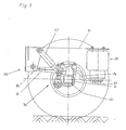
- FIG. 1 shows a chassis frame 10 which consists of side members 11 and cross members 12, with the side members 11 being divided into a front side member section 13 and a rear side member section 14, which are designed as a crank to create a space for a self-steering trailing axle Double angle section 15 are connected.
- a link spring 17 is arranged as the carrier 16 of the axle assembly lentblock trained joint 18 is articulated. At its free end, the link spring 17 is supported against the chassis frame 10 via an air bellows 19.
- the bearing 20 is fixed for the axle 21, wherein the kingpin 22 of the axle 21 is arranged in the space formed by the crank 15 of the side member 11, so that the wheel 24, which on a rim held on the brake drum 26 25 is arranged, can perform the necessary steering movements around the kingpin 22.
- the disadvantage of this known embodiment is that the longitudinal beam 11 cannot be designed continuously, but must be provided with the offset 15, moreover the spring center dimension FM2 is in the area of the self-steering trailing axle compared to the spring center dimension FM1 Rigid axle greatly reduced, which leads to a reduction in the suspension and damping effect.
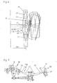
- the chassis frame 30 also consists of side members 31 and cross members 32.
- the side member 31, however, is formed here without any cranking, and a link spring 34 is articulated to the side member 31 as the support 33, which is a first Section 35 has a double-angle section 36 designed as a crank and a support section 37 adjoining it.
- the link spring 34 is fastened to the side member 31 via the joint 38, which is preferably designed as a silent block, while the supporting section 37 is supported on the chassis frame 30 via the air bellows 39 and the cross member 33
- the bearing 40 for the axle 41 is arranged, the structure of which corresponds to the axle configuration according to FIG.
- the base point 51 of the kingpin 42 is arranged in the space 50 created by the offset 36 of the link spring 34 below the side member 31.
- the relevant spring center dimension FM3 is only slightly smaller than the spring center dimension FM1 in the area of the rigid axis.
- the link spring 34 which is cranked at least once to create these possibilities in a horizontal plane, can be designed in all other points like a link spring known per se.
- a crank 44 can be provided in a vertical plane and a shock absorber 43 can be articulated on the bearing 40 of the axle 41 in the usual way.
- the special design of the link spring 34 consists in that the double angle section 36 is arranged as a crank in a horizontal plane so that the axis center line M1 of the section 35 lies in a vertical plane parallel to the longitudinal center axis L1 of the side member 31 and that the axis center line M2 of the support section 37 runs in a horizontal plane parallel to the axis center line M1 of the first section 35.
- the carrier 133 can also be designed as a leaf spring or leaf spring assembly 134.
- the leaf spring 134 is preferably cranked twice in a horizontal plane and has a first section 45 articulated on the longitudinal beam 31, to which a double angle section 46 connects as a crank, which connects the first section 45 to the support section 47, which via a another double-angle section 48 designed as an offset merges into a third section 49 articulated on the longitudinal member 31.
- the linkage to the longitudinal beam 31 is provided via corresponding bearings (38), which in turn can be designed as silent blocks.
- the carrier 33 or 133 as a link spring 34 or leaf spring 134, it is ensured in the provided axle suspension on the chassis frame that the lateral force absorption and transmission to the chassis frame takes place in the same way as with a rigid axle and that, in particular, the force application points far out lie.
Landscapes
- Engineering & Computer Science (AREA)
- Mechanical Engineering (AREA)
- Vehicle Body Suspensions (AREA)
Priority Applications (1)
| Application Number | Priority Date | Filing Date | Title |
|---|---|---|---|
| AT89118370T ATE76819T1 (de) | 1988-10-08 | 1989-10-04 | Achsaufhaengung fuer eine selbstlenkende lkwsattelanh|nger-hinterachse. |
Applications Claiming Priority (2)
| Application Number | Priority Date | Filing Date | Title |
|---|---|---|---|
| DE8812669 | 1988-10-08 | ||
| DE8812669U | 1988-10-08 |
Publications (2)
| Publication Number | Publication Date |
|---|---|
| EP0367986A1 true EP0367986A1 (fr) | 1990-05-16 |
| EP0367986B1 EP0367986B1 (fr) | 1992-06-03 |
Family
ID=6828683
Family Applications (1)
| Application Number | Title | Priority Date | Filing Date |
|---|---|---|---|
| EP89118370A Expired - Lifetime EP0367986B1 (fr) | 1988-10-08 | 1989-10-04 | Suspension d'essieu pour un essieu arrière auto-directeur de semi-remorque |
Country Status (3)
| Country | Link |
|---|---|
| EP (1) | EP0367986B1 (fr) |
| AT (1) | ATE76819T1 (fr) |
| DE (1) | DE58901604D1 (fr) |
Cited By (3)
| Publication number | Priority date | Publication date | Assignee | Title |
|---|---|---|---|---|
| EP2986459B1 (fr) | 2013-06-19 | 2018-06-20 | SAF-HOLLAND GmbH | Bras oscillant longitudinal |
| CN108608819A (zh) * | 2016-12-12 | 2018-10-02 | 扬州中集通华专用车有限公司 | 挂车及其悬挂系统 |
| CN111055646A (zh) * | 2019-12-16 | 2020-04-24 | 扬州维克得瑞科技研发有限公司 | 一种半挂车用减震装置及其减震方法 |
Citations (5)
| Publication number | Priority date | Publication date | Assignee | Title |
|---|---|---|---|---|
| US3241854A (en) * | 1963-05-09 | 1966-03-22 | Gen Motors Corp | Motor vehicle semi-elliptic spring suspension |
| US3944245A (en) * | 1974-08-05 | 1976-03-16 | Kuhn Billy J | Motor vehicle frame assembly |
| FR2450707A1 (fr) * | 1979-03-07 | 1980-10-03 | Essieux Ste Ardennaise | Suspension sur ressorts a lame, avec au moins deux essieux |
| FR2543073A1 (fr) * | 1983-03-22 | 1984-09-28 | Renault | Train arriere de suspension pour vehicule automobile |
| EP0190725A2 (fr) * | 1985-02-06 | 1986-08-13 | Lear Siegler Truck Products Corp. | Suspension pour véhicules automobiles |
-
1989
- 1989-10-04 AT AT89118370T patent/ATE76819T1/de not_active IP Right Cessation
- 1989-10-04 EP EP89118370A patent/EP0367986B1/fr not_active Expired - Lifetime
- 1989-10-04 DE DE8989118370T patent/DE58901604D1/de not_active Expired - Lifetime
Patent Citations (5)
| Publication number | Priority date | Publication date | Assignee | Title |
|---|---|---|---|---|
| US3241854A (en) * | 1963-05-09 | 1966-03-22 | Gen Motors Corp | Motor vehicle semi-elliptic spring suspension |
| US3944245A (en) * | 1974-08-05 | 1976-03-16 | Kuhn Billy J | Motor vehicle frame assembly |
| FR2450707A1 (fr) * | 1979-03-07 | 1980-10-03 | Essieux Ste Ardennaise | Suspension sur ressorts a lame, avec au moins deux essieux |
| FR2543073A1 (fr) * | 1983-03-22 | 1984-09-28 | Renault | Train arriere de suspension pour vehicule automobile |
| EP0190725A2 (fr) * | 1985-02-06 | 1986-08-13 | Lear Siegler Truck Products Corp. | Suspension pour véhicules automobiles |
Cited By (4)
| Publication number | Priority date | Publication date | Assignee | Title |
|---|---|---|---|---|
| EP2986459B1 (fr) | 2013-06-19 | 2018-06-20 | SAF-HOLLAND GmbH | Bras oscillant longitudinal |
| CN108608819A (zh) * | 2016-12-12 | 2018-10-02 | 扬州中集通华专用车有限公司 | 挂车及其悬挂系统 |
| CN108608819B (zh) * | 2016-12-12 | 2024-02-09 | 扬州中集通华专用车有限公司 | 挂车及其悬挂系统 |
| CN111055646A (zh) * | 2019-12-16 | 2020-04-24 | 扬州维克得瑞科技研发有限公司 | 一种半挂车用减震装置及其减震方法 |
Also Published As
| Publication number | Publication date |
|---|---|
| ATE76819T1 (de) | 1992-06-15 |
| DE58901604D1 (de) | 1992-07-09 |
| EP0367986B1 (fr) | 1992-06-03 |
Similar Documents
| Publication | Publication Date | Title |
|---|---|---|
| DE3331282A1 (de) | Radaufhaengung fuer lenkbare vorderraeder von kraftfahrzeugen | |
| EP0324913B1 (fr) | Essieu avant | |
| DE2918605A1 (de) | Einzelradaufhaengung mittels uebereinander angeordneter fuehrungslenker | |
| WO2003008212A1 (fr) | Essieu arriere d'un vehicule automobile dote de cinq bras oscillants | |
| EP0316711A1 (fr) | Suspension indépendante de roue de véhicules automobiles | |
| EP3922489B1 (fr) | Dispositif de ressort x pour une suspension de roue de véhicule automobile | |
| DE3507141A1 (de) | Radaufhaengung fuer lenkbare raeder, insbesondere vorderraeder, von kraftfahrzeugen | |
| DE3047970C2 (de) | Achsaufhängung für Kraftfahrzeuge, insbesondere geländegängige Kraftfahrzeuge | |
| DE3127772C2 (fr) | ||
| EP0367986B1 (fr) | Suspension d'essieu pour un essieu arrière auto-directeur de semi-remorque | |
| DE3030279C2 (de) | Lastzug | |
| DE3012873A1 (de) | Daempferbein-achse fuer personenkraftwagen | |
| DE3205127C2 (fr) | ||
| DE69304236T2 (de) | Radaufhängungsvorrichtung für einen lenkbaren Vorderradsatz eines Nutzfahrzeuges | |
| DE2264278A1 (de) | Vorderradaufhaengung fuer kraftfahrzeuge, insbesondere personenkraftwagen | |
| DE8911790U1 (de) | Achsaufhängung für eine selbstlenkende LKW-Sattelanhänger-Hinterachse | |
| DE19854805A1 (de) | Unabhängige Radaufhängung für Kraftfahrzeuge | |
| DE3448231C2 (de) | Einzelradaufhängung für ein Kraftfahrzeug | |
| DE102020115469A1 (de) | Dolly-Anhänger, Zug-Gespann mit einem solchen Dolly-Anhänger sowie Verfahren zum Betreiben eines solchen Zug-Gespannes | |
| DE69002887T2 (de) | Hinterradaufhängung für Kraftfahrzeuge. | |
| DE69709384T2 (de) | Radaufhängung für fahrzeuge | |
| DE4339856C2 (de) | Radaufhängung, insbesondere für die Hinterräder von Kraftfahrzeugen | |
| DE102018006572B4 (de) | Fahrzeugaufhängungsanordnung für mindestens eine Radachse | |
| DE2622747C3 (de) | Einzelradaufhängung für Anhänger, insbesondere Wohnwagenanhänger | |
| DE69102568T2 (de) | Selbstlenkende Achse für Lastwagen, Anhänger und Sattelanhänger und dergleichen. |
Legal Events
| Date | Code | Title | Description |
|---|---|---|---|
| PUAI | Public reference made under article 153(3) epc to a published international application that has entered the european phase |
Free format text: ORIGINAL CODE: 0009012 |
|
| AK | Designated contracting states |
Kind code of ref document: A1 Designated state(s): AT BE CH DE ES FR GB GR IT LI LU NL SE |
|
| 17P | Request for examination filed |
Effective date: 19900412 |
|
| 17Q | First examination report despatched |
Effective date: 19910829 |
|
| GRAA | (expected) grant |
Free format text: ORIGINAL CODE: 0009210 |
|
| AK | Designated contracting states |
Kind code of ref document: B1 Designated state(s): AT BE CH DE ES FR GB GR IT LI LU NL SE |
|
| PG25 | Lapsed in a contracting state [announced via postgrant information from national office to epo] |
Ref country code: IT Free format text: LAPSE BECAUSE OF FAILURE TO SUBMIT A TRANSLATION OF THE DESCRIPTION OR TO PAY THE FEE WITHIN THE PRE;WARNING: LAPSES OF ITALIAN PATENTS WITH EFFECTIVE DATE BEFORE 2007 MAY HAVE OCCURRED AT ANY TIME BEFORE 2007. THE CORRECT EFFECTIVE DATE MAY BE DIFFERENT FROM THE ONE RECORDED.SCRIBED TIME-LIMIT Effective date: 19920603 Ref country code: GR Free format text: LAPSE BECAUSE OF FAILURE TO SUBMIT A TRANSLATION OF THE DESCRIPTION OR TO PAY THE FEE WITHIN THE PRESCRIBED TIME-LIMIT Effective date: 19920603 Ref country code: ES Free format text: THE PATENT HAS BEEN ANNULLED BY A DECISION OF A NATIONAL AUTHORITY Effective date: 19920603 |
|
| REF | Corresponds to: |
Ref document number: 76819 Country of ref document: AT Date of ref document: 19920615 Kind code of ref document: T |
|
| REF | Corresponds to: |
Ref document number: 58901604 Country of ref document: DE Date of ref document: 19920709 |
|
| GBT | Gb: translation of ep patent filed (gb section 77(6)(a)/1977) | ||
| ET | Fr: translation filed | ||
| PLBE | No opposition filed within time limit |
Free format text: ORIGINAL CODE: 0009261 |
|
| STAA | Information on the status of an ep patent application or granted ep patent |
Free format text: STATUS: NO OPPOSITION FILED WITHIN TIME LIMIT |
|
| 26N | No opposition filed | ||
| EPTA | Lu: last paid annual fee | ||
| EAL | Se: european patent in force in sweden |
Ref document number: 89118370.9 |
|
| REG | Reference to a national code |
Ref country code: FR Ref legal event code: CD |
|
| PGFP | Annual fee paid to national office [announced via postgrant information from national office to epo] |
Ref country code: LU Payment date: 20010830 Year of fee payment: 13 |
|
| PGFP | Annual fee paid to national office [announced via postgrant information from national office to epo] |
Ref country code: CH Payment date: 20011023 Year of fee payment: 13 Ref country code: SE Payment date: 20011023 Year of fee payment: 13 |
|
| REG | Reference to a national code |
Ref country code: GB Ref legal event code: IF02 |
|
| PG25 | Lapsed in a contracting state [announced via postgrant information from national office to epo] |
Ref country code: LU Free format text: LAPSE BECAUSE OF NON-PAYMENT OF DUE FEES Effective date: 20021004 |
|
| PG25 | Lapsed in a contracting state [announced via postgrant information from national office to epo] |
Ref country code: SE Free format text: LAPSE BECAUSE OF NON-PAYMENT OF DUE FEES Effective date: 20021005 |
|
| PG25 | Lapsed in a contracting state [announced via postgrant information from national office to epo] |
Ref country code: CH Free format text: LAPSE BECAUSE OF NON-PAYMENT OF DUE FEES Effective date: 20021031 Ref country code: LI Free format text: LAPSE BECAUSE OF NON-PAYMENT OF DUE FEES Effective date: 20021031 |
|
| EUG | Se: european patent has lapsed | ||
| REG | Reference to a national code |
Ref country code: CH Ref legal event code: PL |
|
| PGFP | Annual fee paid to national office [announced via postgrant information from national office to epo] |
Ref country code: AT Payment date: 20061023 Year of fee payment: 18 |
|
| REG | Reference to a national code |
Ref country code: GB Ref legal event code: 732E |
|
| NLS | Nl: assignments of ep-patents |
Owner name: BPW BERGISCHE ACHSEN KG Effective date: 20080513 |
|
| NLT1 | Nl: modifications of names registered in virtue of documents presented to the patent office pursuant to art. 16 a, paragraph 1 |
Owner name: FELDBINDER & BECKMANN FAHRZEUGBAU GMBH & CO. KG. |
|
| PG25 | Lapsed in a contracting state [announced via postgrant information from national office to epo] |
Ref country code: AT Free format text: LAPSE BECAUSE OF NON-PAYMENT OF DUE FEES Effective date: 20071004 |
|
| PGFP | Annual fee paid to national office [announced via postgrant information from national office to epo] |
Ref country code: NL Payment date: 20081023 Year of fee payment: 20 |
|
| REG | Reference to a national code |
Ref country code: FR Ref legal event code: TP |
|
| PGFP | Annual fee paid to national office [announced via postgrant information from national office to epo] |
Ref country code: DE Payment date: 20081029 Year of fee payment: 20 |
|
| PGFP | Annual fee paid to national office [announced via postgrant information from national office to epo] |
Ref country code: BE Payment date: 20081024 Year of fee payment: 20 |
|
| PGFP | Annual fee paid to national office [announced via postgrant information from national office to epo] |
Ref country code: FR Payment date: 20081021 Year of fee payment: 20 |
|
| PGFP | Annual fee paid to national office [announced via postgrant information from national office to epo] |
Ref country code: GB Payment date: 20081024 Year of fee payment: 20 |
|
| REG | Reference to a national code |
Ref country code: GB Ref legal event code: PE20 Expiry date: 20091003 |
|
| BE20 | Be: patent expired |
Owner name: *BPW BERGISCHE ACHSEN K.G. Effective date: 20091004 |
|
| NLV7 | Nl: ceased due to reaching the maximum lifetime of a patent | ||
| PG25 | Lapsed in a contracting state [announced via postgrant information from national office to epo] |
Ref country code: NL Free format text: LAPSE BECAUSE OF EXPIRATION OF PROTECTION Effective date: 20091004 |
|
| PG25 | Lapsed in a contracting state [announced via postgrant information from national office to epo] |
Ref country code: GB Free format text: LAPSE BECAUSE OF EXPIRATION OF PROTECTION Effective date: 20091003 |