EP2986459B1 - Bras oscillant longitudinal - Google Patents
Bras oscillant longitudinal Download PDFInfo
- Publication number
- EP2986459B1 EP2986459B1 EP14730899.3A EP14730899A EP2986459B1 EP 2986459 B1 EP2986459 B1 EP 2986459B1 EP 14730899 A EP14730899 A EP 14730899A EP 2986459 B1 EP2986459 B1 EP 2986459B1
- Authority
- EP
- European Patent Office
- Prior art keywords
- axle tube
- control arm
- arrangement section
- trailing arm
- longitudinal control
- Prior art date
- Legal status (The legal status is an assumption and is not a legal conclusion. Google has not performed a legal analysis and makes no representation as to the accuracy of the status listed.)
- Active
Links
Images


Classifications
-
- B—PERFORMING OPERATIONS; TRANSPORTING
- B60—VEHICLES IN GENERAL
- B60G—VEHICLE SUSPENSION ARRANGEMENTS
- B60G7/00—Pivoted suspension arms; Accessories thereof
- B60G7/001—Suspension arms, e.g. constructional features
-
- B—PERFORMING OPERATIONS; TRANSPORTING
- B60—VEHICLES IN GENERAL
- B60G—VEHICLE SUSPENSION ARRANGEMENTS
- B60G7/00—Pivoted suspension arms; Accessories thereof
- B60G7/008—Attaching arms to unsprung part of vehicle
-
- B—PERFORMING OPERATIONS; TRANSPORTING
- B60—VEHICLES IN GENERAL
- B60G—VEHICLE SUSPENSION ARRANGEMENTS
- B60G7/00—Pivoted suspension arms; Accessories thereof
- B60G7/02—Attaching arms to sprung part of vehicle
-
- B—PERFORMING OPERATIONS; TRANSPORTING
- B60—VEHICLES IN GENERAL
- B60G—VEHICLE SUSPENSION ARRANGEMENTS
- B60G9/00—Resilient suspensions of a rigid axle or axle housing for two or more wheels
- B60G9/003—Resilient suspensions of a rigid axle or axle housing for two or more wheels the axle being rigidly connected to a trailing guiding device
-
- B—PERFORMING OPERATIONS; TRANSPORTING
- B60—VEHICLES IN GENERAL
- B60G—VEHICLE SUSPENSION ARRANGEMENTS
- B60G9/00—Resilient suspensions of a rigid axle or axle housing for two or more wheels
- B60G9/02—Resilient suspensions of a rigid axle or axle housing for two or more wheels the axle or housing being pivotally mounted on the vehicle, e.g. the pivotal axis being parallel to the longitudinal axis of the vehicle
-
- B—PERFORMING OPERATIONS; TRANSPORTING
- B60—VEHICLES IN GENERAL
- B60G—VEHICLE SUSPENSION ARRANGEMENTS
- B60G2200/00—Indexing codes relating to suspension types
- B60G2200/30—Rigid axle suspensions
- B60G2200/31—Rigid axle suspensions with two trailing arms rigidly connected to the axle
-
- B—PERFORMING OPERATIONS; TRANSPORTING
- B60—VEHICLES IN GENERAL
- B60G—VEHICLE SUSPENSION ARRANGEMENTS
- B60G2204/00—Indexing codes related to suspensions per se or to auxiliary parts
- B60G2204/10—Mounting of suspension elements
- B60G2204/14—Mounting of suspension arms
- B60G2204/143—Mounting of suspension arms on the vehicle body or chassis
-
- B—PERFORMING OPERATIONS; TRANSPORTING
- B60—VEHICLES IN GENERAL
- B60G—VEHICLE SUSPENSION ARRANGEMENTS
- B60G2204/00—Indexing codes related to suspensions per se or to auxiliary parts
- B60G2204/10—Mounting of suspension elements
- B60G2204/14—Mounting of suspension arms
- B60G2204/148—Mounting of suspension arms on the unsprung part of the vehicle, e.g. wheel knuckle or rigid axle
-
- B—PERFORMING OPERATIONS; TRANSPORTING
- B60—VEHICLES IN GENERAL
- B60G—VEHICLE SUSPENSION ARRANGEMENTS
- B60G2206/00—Indexing codes related to the manufacturing of suspensions: constructional features, the materials used, procedures or tools
- B60G2206/01—Constructional features of suspension elements, e.g. arms, dampers, springs
- B60G2206/012—Hollow or tubular elements
-
- B—PERFORMING OPERATIONS; TRANSPORTING
- B60—VEHICLES IN GENERAL
- B60G—VEHICLE SUSPENSION ARRANGEMENTS
- B60G2206/00—Indexing codes related to the manufacturing of suspensions: constructional features, the materials used, procedures or tools
- B60G2206/01—Constructional features of suspension elements, e.g. arms, dampers, springs
- B60G2206/10—Constructional features of arms
-
- B—PERFORMING OPERATIONS; TRANSPORTING
- B60—VEHICLES IN GENERAL
- B60G—VEHICLE SUSPENSION ARRANGEMENTS
- B60G2206/00—Indexing codes related to the manufacturing of suspensions: constructional features, the materials used, procedures or tools
- B60G2206/01—Constructional features of suspension elements, e.g. arms, dampers, springs
- B60G2206/80—Manufacturing procedures
- B60G2206/82—Joining
- B60G2206/8201—Joining by welding
Definitions
- the present invention relates to a trailing arm for connecting an axle tube to a vehicle frame and affyachssystem, in particular for a commercial vehicle.
- Trailing arms of the type in question are known from the prior art. They come z. B. in Starrachs- or in steering axle systems of commercial vehicles for use. They serve to connect an axle tube to a vehicle or to a vehicle frame and ensure lateral guidance of the axle tube. In addition, they are part of the suspension and damping system of the chassis and have as such appropriate connection options for spring or damper elements.
- the known trailing arm however, have the disadvantage that they build very large and heavy, since high forces must be transmitted. This narrows the tight space below the vehicle or below the vehicle frame in addition. An optimal connection trailing arm to the axle tube and the trailing arm to the vehicle frame is often not possible. In addition, there are usually restrictions on the use of wide tires, large drum brakes or large disc brakes, as the known trailing arms build too wide. When used in steering systems, the realizable steering angles are often smaller than desired.
- the EP 2 397 340 A2 discloses a trailing arm for connecting an axle tube to a vehicle frame which extends along a longitudinal direction and has a frame-side disposition portion and at least one axle tube-side disposition portion, wherein a center line of the axle tube-side disposition portion transverse to the longitudinal direction is displaced by an offset to a center line of the frame-side arrangement portion, wherein the trailing arm is formed at least partially as a hollow profile, wherein the trailing arm has a carrier top and a carrier base, wherein the carrier upper part and / or the carrier base each have an axle tube side arrangement portion wherein the carrier top and the carrier base form a dividing plane which is at an angle to the horizontal plane. It is therefore an object of the present invention to provide a trailing arm for connecting an axle tube to a vehicle frame and aggyachssystem, which eliminate the disadvantages mentioned and allow a more flexible arrangement of the trailing arm or both the vehicle frame and the axle tube.
- a trailing arm for connecting an axle tube to a vehicle frame which extends along a longitudinal direction and has a frame-side locating portion and at least one axle tube-side locating portion, wherein a center line of the axle tube-side locating portion displaces transversely to the longitudinal direction toward a center line of the frame-side locating portion by an offset
- the trailing arm is at least partially formed as a hollow profile
- the trailing arm has a carrier top and a carrier base, wherein the carrier upper part and / or the carrier base each have a Achsrohr facilityen arrangement portion, wherein the carrier upper part and the lower carrier part form a dividing plane, which at an angle to the horizontal plane, wherein the one or more axle tube side arrangement sections have a wrap angle ⁇ 180 °.
- the trailing arm can also be used on trailers, trailers, etc.
- Axles or rigid axles for utility vehicles (as well as for trailers, trailers, etc.), both steered and unguided, usually comprise an axle tube which has a stub axle at both ends.
- the brake system and the tires etc. are arranged at the stub axles z.
- Such an axle is usually connected via two trailing arms (sometimes called function link) with the vehicle frame or with the chassis pivotally connected.
- the trailing arms are oriented substantially along the direction of travel. The longitudinal direction thus corresponds essentially to the direction of travel.
- the axle tube is arranged substantially transversely or at right angles to the trailing arms or the direction of travel on the trailing arms or in these.
- Axle tube and trailing arm can be directly connected to each other, for example, welded, be.
- a shell also called a wrap
- the trailing arm has the frame-side arrangement section, for the arrangement on the axle tube or for the arrangement of the axle tube, the axle tube-side arrangement section.
- Said shell can be arranged, for example, on the axle tube side arrangement section or within it.
- the frame-side arrangement section and the axle tube-side arrangement section are spaced apart from one another, wherein the spacing essentially denotes the distance of pivot points or centers of the arrangement sections.
- the distance is substantially parallel to a horizontal plane, ie to the road surface. He can also run diagonally. This applies equally to the longitudinal direction, which runs essentially along the distance.
- the frame-side arrangement portion and the axis-side arrangement portion each have a width.
- the frame-side arrangement portion is formed by a round substantially circular opening, which extends substantially transversely to the longitudinal direction.
- the opening in the cross section is not straight around, but z. B. oval, polygonal and / or angular.
- rubber bearings or the like are used, which generally have a round hole in the middle of the center for inserting an axis or the like.
- an outer contour of the rubber bearing just not round or circular to prevent twisting in the frame-side arrangement portion can with advantage so z. B. also oval or be formed polygonal.
- Transverse to the longitudinal direction of the frame-side arrangement portion or its inner contour has the width, which is preferably substantially constant.
- the center line of the frame-side arrangement section intersects the contour substantially centrally or axisymmetrically.
- the axle tube side arrangement section which also preferably represents an opening which extends substantially transversely to the longitudinal direction with the width.
- the opening is substantially round or in particular circular.
- the opening is also oval, polygonal and / or angular.
- the centerline of the axle tube side arrangement section divides the width substantially centrally or axisymmetrically.
- the center lines of both the frame-side arrangement portion and the axle tube-side arrangement portion are substantially parallel to the longitudinal direction and displaced by the offset.
- the offset is in a range of 10 mm to 200 mm, preferably in a range of 30 mm to 150 mm, more preferably in a range of about 40 mm to 100 mm.
- a ratio of the offset to the distance between the axle tube side and the frame side disposition section is in a range of about 0.01 to 0.4, preferably in a range of 0.04 to 0.3, more preferably in a range of about 0.05 to 0.2.
- the frame-side locating portion and the achsrohr maybee locating portion are preferably not along a line or not in alignment as seen along the longitudinal direction or the direction of travel.
- the trailing arm by the offset other objects so to speak dodge.
- the offset is achieved by different widths of the axle tube side and the frame-side arrangement portion.
- the trailing arm can have substantially the same width along the longitudinal direction, so to speak, only the arrangement sections being displaced from one another or offset, or even only their center lines.
- the frame-side and the axle tube-side arrangement portion are also the same width, in which case determines the shape of the trailing arm along the longitudinal direction of the offset.
- the trailing arm takes in a plan view (seen in the installed state on the road plane) in about an S-shape.
- an S-shape can of course also be combined with differently wide arrangement sections become.
- this is an extremely flexible adaptation to the space available below the vehicle.
- the trailing arm namely a different support width on the vehicle and the axle tube.
- the term supporting distance defines the distance of two corresponding arrangement sections (on the frame side and / or axle tube side) of two adjacently arranged trailing arms transversely to the longitudinal direction.
- different support widths can be achieved by the offset.
- the Abstützweite the vehicle is greater than the Abstützweite the axle tube, alternatively preferably also vice versa.
- the wide support on the vehicle allows extremely stable storage of the entire body. It is thus of great advantage if the center line of the axle tube-side arrangement section is displaced by the offset from the center line of the frame-side arrangement section to a chassis centerline. This is the greatest possible support of the trailing arm on the vehicle with simultaneous space gain, for example, for wide tires, created.
- a Lenkachsaus in addition to the wide support on the vehicle and the possible use of a wide tires in addition a much larger steering angle or steering angle possible.
- the additionally gained on the outside space here not only benefits a wider tires, but can also be used to more easily or broader drum brakes or longer-built disc brakes easier to adapt or facilitate their installation. It is understood that it is also possible to arrange two trailing arms, which have the offset, such that the support width on the vehicle is the same as on the axle tube.
- the trailing arm is at least partially formed as a hollow profile, wherein the hollow profile preferably has a cross-section which increases at least in regions in the direction of the frame-side arrangement portion.
- the hollow profile is preferably a box profile welded together from individual parts. Particularly preferred is the hollow profile but with a hydroforming process (IHU) produced.
- the cross-section of the hollow profile increases at least in sections in the direction of the frame-side arrangement section.
- the trailing arm is advantageously shaped such that it has a dirt-repellent design, in which no undercuts, troughs and depressions, etc. are executed, whereby the possibility is given to prevent harmful dirt accumulation by stones, dust and salt water.
- Another advantage of a transition-free and self-contained trailing arm shape is a low-resistance, streamlined design that counteracts extreme air turbulence under the vehicle.
- the wall thickness is flexibly tuned to the expected load of the trailing arm by the hydroforming process.
- the trailing arm can be designed as a framework. Also, by using a truss structure optimal alignment based on the forces occurring can be made possible.
- the trailing arm has a curvature transverse to a horizontal plane, wherein the curvature preferably extends between the axle tube side and the frame-side locating portion.
- the horizontal plane expediently corresponds to a plane on which the pivot axis of the frame-side arrangement section and the center axis of the axle tube-side arrangement section lie, and in particular essentially the road plane.
- the curvature extends to the entire trailing arm or to its entire cross section, ie not only for example on an upper edge of the trailing arm. Namely, with great advantage, the curvature forms, as it were, a free space below or between the frame-side and the axle tube-side arrangement section.
- the curvature thus serves not the frame-side and the axle tube side arrangement section directly, so by the shortest route straight to connect, but in an arc, so to speak, wherein the arc or the curvature between the axle tube side and the frame-side arrangement portion extends.
- the arch or buckle extends away from the horizontal plane.
- the arc or the curvature extends straight to the horizontal plane. Under certain circumstances, although the ground clearance is reduced, but it can be significantly increased the compression travel, since the space requirement of the trailing arm is minimal upwards.
- the curvature or the arc has a maximum extent substantially transversely to the horizontal plane, starting from the pivot point of the frame-side locating portion, which preferably lies in a range of about 50 mm to 200 mm.
- the extent is measured perpendicular to the distance of the pivot points or centers of the frame-side and the axle tube side arrangement section.
- a ratio of the extent to the spacing of the two arrangement sections lies in a range of about 0.1 to 0.5, particularly preferably in a range of about 0.2 to 0.3.
- the trailing arm on a carrier shell and a lower carrier part wherein the upper carrier part and the lower carrier part, in particular their separation surface or contact surface, form a dividing plane, which is at an angle to the horizontal plane.
- the dividing plane extends through the axle tube side arrangement section. Particularly preferred also by the fulcrum or center of the achsohr Wennen arrangement section.
- the dividing plane preferably cuts the axle tube-side arrangement section.
- the trailing arm is thus divided in the region of the axle tube side arrangement section.
- the angle between the dividing plane and the horizontal plane in a preferred embodiment is approximately 180 °.
- the dividing plane is thus essentially preferably parallel to the horizontal plane or to the roadway plane.
- the carrier upper part and the lower carrier part need not necessarily be connected to each other. Both can be positively and / or non-positively connected to the axle tube, for example, without touching each other.
- the carrier upper part and the lower carrier part are connected to one another via at least one contact surface.
- the contact surface is within the division plane or is a part of them.
- the carrier upper part and / or the lower carrier part each have an axle tube side arrangement section, wherein the one or more axle tube side arrangement sections have a wrap angle ⁇ 180 °.
- the axle tube-side arrangement section of the trailing arm is formed by the axle tube-side arrangement sections of the carrier upper part and of the carrier lower part. All the advantages and features already mentioned regarding the arrangement sections apply.
- the division into the carrier upper part and the lower carrier part or the use of at least two axle tube side arrangement sections allows advantageously that z.
- B. the achsrohr gase arrangement portion of the carrier upper part is made wider than that of the lower part or vice versa. Appropriately, so that the power flow can be optimized.
- a great advantage of a wrap angle ⁇ 180 ° is that the axle tube does not have to be pushed into the trailing arm, but rather that the trailing arm or the carrier upper parts or the carrier lower parts can be placed on the axle tube.
- a trailing arm which is not formed from a carrier shell and a carrier base, may have a wrap angle ⁇ 180 °.
- Carrier shell which each have a wrap angle ⁇ 180 °, in sum, again a wrap angle achievable, which is> 180 °.
- the carrier shell and / or the carrier base are positively and / or non-positively connected to an adapter plate, wherein the adapter plate is positively and / or non-positively connected to a support surface which is designed for the arrangement of a spring / damper element.
- the trailing arm is therefore designed in three parts, so to speak, in total, wherein the three parts are connected to one another via the adapter plate.
- the trailing arm can also be formed in one piece, in which case the support surface is a part of the trailing arm.
- the support surface may also be a part of the carrier base or a part of the carrier shell.
- the upper carrier part, the lower carrier part and / or the support surface are welded to the adapter plate in abutment.
- the adapter plate can preferably also have an opening through which the carrier lower part, the carrier upper part and / or the support surface can protrude, which allows circumferential welding (along the outer contour of said parts) with the adapter plate.
- the upper carrier part and the lower carrier part can also be screwed together.
- the adapter plate allows the combination of different materials.
- the trailing arm or the upper carrier part and / or the lower carrier part are made of a steel or aluminum material, while on the adapter plate a support surface made of a composite or composite material, for example, form and / or non-positively can be arranged via suitable screw.
- the trailing arm on the axle tube-side arrangement section for connecting the axle tube and / or the shell has at least one projection which extends substantially along the axle tube.
- the projection has the same wrap angle as the trailing arm or the upper carrier part or the lower carrier part. It is understood that more than one projection can be arranged circumferentially around the axle tube.
- an arrangement on both sides of the trailing arm or the axle tube side Arrangement section possible.
- a projection is preferably arranged on the carrier upper part, on both sides of the link.
- the projection can be welded, for example, on the trailing arm or on the upper carrier part and / or on the lower carrier part.
- the said components can also form the projection itself.
- the projection then does not need to be extra attached.
- the projection advantageously has a contact area to the axle tube or to the shell.
- the contact area essentially forms a line contact and not a surface contact.
- a line contact is provided with advantage.
- the projection has expediently therefore not with its entire width or with its entire height in contact with the component to be connected or arranged. Due to the extremely favorable introduction of force into the axle tube, the trailing arm, which has the projection or protrusions, can advantageously be connected to the axle tube without the shell. It is understood that the trailing arm can also have at least one projection on the frame-side arrangement section. All advantages and features apply in the same way.
- the at least one projection connects the trailing arm and the axle tube and / or the shell in an arc.
- the arc extends substantially transversely to the longitudinal direction of the trailing arm to the axle tube.
- the bow can be made convex or concave.
- it is designed such that a power flow between the axle tube and the trailing arm can be optimized.
- the arc represents, so to speak, a connection of the two line contacts.
- the arc allows a very rigid connection of the axle tube.
- the projection so to speak, the width of the axle tube side arrangement portion can be increased. The load peaks on the axle tube decrease.
- the power flow between the trailing arm and the axle tube is reduced because the projection provides an additional "force path" through the line contact.
- the connection between the trailing arm and the axle tube is also possible only via the projections or protrusions, that is, the original one or actual achsrohr gase arrangement region of the trailing arm has no direct contact with the axle tube.
- the welding of the trailing arm with the axle tube takes place at least partially along the projection. It is understood that the projection can also be welded to the shell.
- a projection is arranged on both sides of the axle tube-side arrangement section, wherein the two projections preferably have a different width.
- the width is measured essentially transversely to the longitudinal direction and along the axle tube.
- the offset of the center line of the frame-side arrangement section to the center line of the axle tube-side arrangement section can be further varied by using projections of different widths.
- the projection advantageously has a (maximum) height.
- a height / width ratio of the protrusion is in a range of about 0.2 to 1.8, preferably about 0.7 to 1.8, more preferably about 0.8 to 1.2.
- a vehicle axle system in particular for a utility vehicle, is provided with a trailing arm for connecting an axle tube to a vehicle frame as described above. It is understood that all advantages and features of the trailing arm according to the invention also apply to the Anlagenachssystem invention and vice versa. Further advantages and features will become apparent from the following description of preferred embodiments of the trailing arm and thehariachssystem invention with reference to the accompanying figures. Individual features of the individual embodiments can be combined with each other within the scope of the invention.
- Fig. 1 shows a schematic representation of a trailing arm 20 in a plan view (on a road surface).
- the trailing arm 20 has, along a longitudinal axis L, a frame-side arrangement section 22 and an axle tube-side arrangement section 24.
- a center line M22 of the frame-side arrangement section is displaced by an offset x to a center line M24 of the axle tube-side arrangement section.
- an axle tube 10 is arranged within the axle tube side assembly portion 24, an axle tube 10 is arranged.
- a width b22 of the frame-side arrangement portion 22 is significantly narrower than a width b24 of the tube side Arrangement Section 24. This difference ultimately achieves the offset x.
- the trailing arm 20 is connected via an adapter plate 60 with a support surface 26.
- FIG. 2 shows a schematic representation of a preferred embodiment of a trailing arm 20 in a plan view.
- a frame-side arrangement section 22 has a width b22 which corresponds approximately to a width b24 of an axle tube-side arrangement section 24.
- a center line M22 of the frame-side arrangement section 22 is displaced by an offset x to a center line M24 of the axle tube-side arrangement section 24.
- the offset x is achieved in this case via the S-shape of the trailing arm 20.
- Fig. 3 shows a further preferred embodiment of a trailing arm 20 in a side view.
- the trailing arm 20 comprises a carrier upper part 42 which has a curvature 30 and a carrier lower part 44.
- the curvature 30 has a maximum extent a, wherein the extension is perpendicular to the distance of the pivot points or centers D22 and D24 of the frame-side 22 and the axle tube side arrangement section 24 dimensions.
- the distance of the pivot points or centers D22 and D24 is aligned substantially parallel to the longitudinal direction L as well as to a horizontal plane E.
- the upper carrier part 42 and the lower carrier part 44 are connected via a common contact surface 46 which lies within a dividing plane T.
- the dividing plane T or the contact surface 46 lies substantially parallel to the horizontal plane E. Both the upper carrier part 42 and the lower carrier part 44 wrap with their respective axle tube side arrangement sections 24 an axle tube (not shown here) with angles of wrap ⁇ 180 °. In addition to the contact surface 46, the carrier upper part 42 and the lower carrier part 44 are connected via an adapter plate 60. Next, a support surface 26 is arranged on the adapter plate 60, which serves the arrangement of a spring / damper element, for example an air spring bellows. The entire trailing arm 20 extends substantially along the longitudinal direction L, which is oriented substantially parallel to the horizontal plane E.
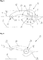
- Fig. 4 shows a further preferred embodiment of a trailing arm 20 in a side view.
- the trailing arm 20 is connected via a shell 12 with an axle tube (not shown here) connectable.
- the shell 12 is connected by an axle tube side arrangement portion 24 of the trailing arm 20, in which case a wrap angle> 180 ° is realized.
- the trailing arm 20 is formed integrally in the illustrated embodiment and forms at its rear end a support surface 26 and between the axle tube side assembly portion 24 and a frame-side arrangement portion 22 a bulge 30.
- the buckle 30 extends substantially away from a horizontal plane E.
- Fig. 5 shows a further preferred embodiment of a trailing arm 20 in a side view.
- the trailing arm 20 has a carrier upper part 42 and a lower carrier part 44, which form a dividing plane T with their respective axle tube-side arrangement sections 24.
- the carrier lower part 44 further has a support surface 26.
- the division plane T forms an angle ⁇ with a horizontal plane E.
- the carrier upper part 42 has a frame-side arrangement section 22.
- a curvature 30 is formed which, as it were, creates a clearance between the frame-side arrangement section 22 and the axle tube-side arrangement section 24.
- the upper carrier part 42 and the lower carrier part 44 are in the in Fig. 5 embodiment shown not directly connected.
- Fig. 6 shows a preferred embodiment of a Achsrohr facilityen arrangement portion 24 in a sectional view transverse to a longitudinal direction L and along an axle tube 10.
- the trailing arm comprises a carrier shell 42 and a support base 44.
- the support base 44 is welded directly over welds S and the axle tube 10.
- the carrier upper part 42 has on both sides each have a projection 28, which extend substantially concave from the upper carrier part 42 to the axle tube 10. Transverse to the axle tube 10 and to the longitudinal axis L, the projections have a height h28.
- the two projections 28 via welds S with the
- the projections 28 may also represent or have a rather convex or straight shape in cross section.
- the two projections 28 have no area but line contact with the axle tube 10 and with the carrier upper part 42. Along the line contact, the welding takes place with advantage.
- Fig. 6 shows further that now from above over four points a force can take place in the axle tube 10, characterized in that the two (contact) points of the carrier upper part 42, the two (contact) locations of the projections 28 added. It is understood that a force application would be possible only on the projections 28. It can also be seen clearly that along the axle tube 10, the two projections 28 have different widths.
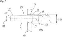
- Fig. 7 shows a further preferred embodiment of a trailing arm 20 in a plan view.
- the trailing arm 20 has a frame-side arrangement section 22 and an axle tube-side arrangement section 24.
- At the achsrohr facilityen arrangement portion 24 is arranged on each side of a respective projection 28, wherein the widths b28 of the projections 28 are formed differently.
- a center line M24 of the tube side arrangement section 24 is oriented by an offset x shifted to a center line M22 of the frame side arrangement section 22. It is understood that projections 28 of different widths can also be combined with trailing arms 20, which already have the offset x between the frame-side arrangement section 22 and the axle tube-side arrangement section 24.
- the offset x is realized via the differently wide projections 28.
- the two arrangement sections would be approximately the same width due to the longitudinal trailing arm shape constant.
- a width b24 of the axis-side arrangement section 24 can now be wider than a width b22 of the frame-side arrangement section.
Landscapes
- Engineering & Computer Science (AREA)
- Mechanical Engineering (AREA)
- Vehicle Body Suspensions (AREA)
Claims (8)
- Bras oscillant longitudinal (20) pour attacher un tube d'essieu (10) sur un châssis de véhicule, qui s'étend le long d'une direction longitudinale (L) et qui comprend une portion de montage côté châssis (22) et au moins une portion de montage côté tube d'essieu (24), dans lequel une ligne médiane (M24) de la portion de montage côté tube d'essieu (24), vue transversalement à la direction longitudinale (L), est décalée d'un décalage (x) par rapport à une ligne médiane (M22) de la portion de montage côté châssis (22),
le bras oscillant longitudinal (20) est réalisé au moins localement sous forme de profilé creux,
le bras oscillant longitudinal (20) comprend une partie de support supérieure (42) et une partie de support inférieure (44), et
la partie de support supérieure (42) et/ou la partie de support inférieure (44) présentent chacune une portion de montage côté tube d'essieu (24),
la partie de support supérieure (42) et la partie de support inférieure (44) forment un plan de séparation (T) qui définit un angle (α) avec le plan horizontal (E),
caractérisé en ce que
la ou les portions côté tube d'essieu (24) présente(nt) un angle d'enlacement (ϕ) < 180°. - Bras oscillant longitudinal (20) selon la revendication 1,
dans lequel le profilé creux présente de préférence une section transversale qui augmente au moins localement en direction de la portion de montage côté châssis (22). - Bras oscillant longitudinal (20) selon la revendication 1 ou 2,
dans lequel le bras oscillant longitudinal (20) présente un bombement (30) transversalement à un plan horizontal (E),
et le bombement s'étend de préférence entre la portion de montage côté tube d'essieu (24) et la portion de montage côté châssis (22). - Bras oscillant longitudinal (20) selon l'une des revendications précédentes,
dans lequel la partie de support supérieure (42) et/ou la partie de support inférieure (44) sont reliées par coopération de formes et/ou de forces à un panneau adaptateur (60), et le panneau adaptateur (60) est relié par coopération de formes et/ou de forces à une surface de support (26) qui est conçue pour l'agencement d'un élément à ressort et/ou amortisseur. - Bras oscillant longitudinal (20) selon l'une des revendications précédentes,
dans lequel le bras oscillant longitudinal (20) présente au moins une saillie (28) sur la portion de montage côté tube d'essieu (24) pour attacher le tube d'essieu (10) et/ou une coque (12), ladite saillie s'étendant sensiblement le long du tube d'essieu (10). - Bras oscillant longitudinal (20) selon la revendication 5,
dans lequel ladite au moins une saillie (28) relie le bras oscillant longitudinal (20) et le tube d'essieu (10) et/ou la coque (12) dans un coude. - Bras oscillant longitudinal (20) selon l'une des revendications 5 ou 6,
dans lequel la saillie (28) est agencée de part et d'autre de la portion de montage côté tube d'essieu (24), et
les deux saillies (28) présentent de préférence une largeur différente (b). - Système d'essieu de véhicule, en particulier pour un véhicule utilitaire, comportant un bras oscillant longitudinal (20) selon l'une des revendications 1 à 7.
Applications Claiming Priority (2)
| Application Number | Priority Date | Filing Date | Title |
|---|---|---|---|
| DE102013211468.0A DE102013211468B4 (de) | 2013-06-19 | 2013-06-19 | Längslenker |
| PCT/EP2014/062642 WO2014202563A1 (fr) | 2013-06-19 | 2014-06-17 | Bras oscillant longitudinal |
Publications (2)
| Publication Number | Publication Date |
|---|---|
| EP2986459A1 EP2986459A1 (fr) | 2016-02-24 |
| EP2986459B1 true EP2986459B1 (fr) | 2018-06-20 |
Family
ID=50972716
Family Applications (1)
| Application Number | Title | Priority Date | Filing Date |
|---|---|---|---|
| EP14730899.3A Active EP2986459B1 (fr) | 2013-06-19 | 2014-06-17 | Bras oscillant longitudinal |
Country Status (7)
| Country | Link |
|---|---|
| US (1) | US9662949B2 (fr) |
| EP (1) | EP2986459B1 (fr) |
| CN (1) | CN105307878B (fr) |
| AU (1) | AU2014283417B2 (fr) |
| DE (1) | DE102013211468B4 (fr) |
| RU (1) | RU2647113C2 (fr) |
| WO (1) | WO2014202563A1 (fr) |
Families Citing this family (3)
| Publication number | Priority date | Publication date | Assignee | Title |
|---|---|---|---|---|
| DE102013210142A1 (de) * | 2013-05-31 | 2014-12-04 | Saf-Holland Gmbh | Lenkereinheit |
| DE102015214456A1 (de) * | 2015-07-30 | 2017-02-02 | Deere & Company | Kabinenlagerungsanordnung für ein Nutzfahrzeug |
| BR112018068821A2 (pt) * | 2016-03-17 | 2019-01-22 | Saf Holland Inc | conjunto de suspensão de veículo motorizado |
Citations (12)
| Publication number | Priority date | Publication date | Assignee | Title |
|---|---|---|---|---|
| EP0367986A1 (fr) | 1988-10-08 | 1990-05-16 | FELDBINDER & BECKMANN oHG | Suspension d'essieu pour un essieu arrière auto-directeur de semi-remorque |
| DE3913697A1 (de) | 1989-04-26 | 1990-10-31 | Bergische Achsen Kotz Soehne | Achsaggregat |
| US5203585A (en) | 1991-07-12 | 1993-04-20 | Neway Corp. | Split-beam suspension system |
| GB2396140A (en) | 2002-12-13 | 2004-06-16 | Meritor Heavy Vehicle Sys Ltd | A cast suspension trailing arm for heavy commercial vehicles |
| EP1671821A1 (fr) | 2004-12-17 | 2006-06-21 | ArvinMeritor Technology, LLC | Suspension à bras oscillant |
| US20060181047A1 (en) | 2005-02-14 | 2006-08-17 | Chamberlin Michael A | Trailing arm for a vehicle suspension |
| DE102005022745A1 (de) | 2005-03-30 | 2006-10-05 | Otto Sauer Achsenfabrik Gmbh | Fahrzeugachsaggregat |
| EP1728654A1 (fr) | 2005-06-03 | 2006-12-06 | Meritor Heavy Vehicle Systems Limited | Suspension à bras tirés |
| DE19818698B4 (de) | 1997-11-21 | 2010-12-02 | Saf-Holland Gmbh | Aufhängung für eine Fahrzeugachse |
| EP2355988A1 (fr) | 2008-12-09 | 2011-08-17 | BPW Bergische Achsen KG | Suspension d'essieu pour un essieu de véhicule |
| EP2397340A2 (fr) | 2010-06-16 | 2011-12-21 | Gigant-Trenkamp & Gehle GmbH | Axe de véhicule automobile |
| CA2727344A1 (fr) | 2010-12-23 | 2012-06-23 | Breton, Etienne | Systeme de suspension de vehicule a coussins pneumatiques |
Family Cites Families (18)
| Publication number | Priority date | Publication date | Assignee | Title |
|---|---|---|---|---|
| US5375871A (en) * | 1993-07-02 | 1994-12-27 | Ridewell Corporation | Vehicle suspension system comprising a wide base beam and axle shell |
| US5690353A (en) * | 1996-05-09 | 1997-11-25 | Suspensions Incorporated | Suspension system with improved beam |
| DE29616257U1 (de) * | 1996-09-19 | 1996-11-07 | Otto Sauer Achsenfabrik Keilberg, 63856 Bessenbach | Aufhängung für luftgefederte Fahrzeugradachse |
| GB0021716D0 (en) * | 2000-09-05 | 2000-10-18 | Meritor Heavy Vehicle Sys Ltd | Vehicle suspension axle wrap |
| US6834874B1 (en) * | 2002-10-07 | 2004-12-28 | Jerry Overby | Trailer suspension system |
| US6827360B2 (en) * | 2002-10-24 | 2004-12-07 | Arvinmeritor Technology, Llc | One-piece trailing arm section |
| US7347435B2 (en) * | 2005-01-14 | 2008-03-25 | Watson & Chalin Manufacturing, Inc. | Suspension system having reduced weight arm construction |
| DE202005004965U1 (de) * | 2005-03-30 | 2005-05-25 | Otto Sauer Achsenfabrik Gmbh | Fahrzeugachsaggregat |
| DE102006009441B4 (de) * | 2006-03-01 | 2008-09-04 | Saf-Holland Gmbh | Gusslenker mit integrierter Stahlbuchse |
| DE102006015671B4 (de) * | 2006-04-04 | 2020-01-02 | Bpw Bergische Achsen Kg | Fahrzeug-Achskörper |
| GB0619981D0 (en) * | 2006-10-10 | 2006-11-15 | Meritor Heavy Vehicle Sys Ltd | Suspension sub-assembly |
| NL1034756C1 (nl) * | 2007-07-20 | 2009-01-21 | Weweler Nv | Wielasophanging. |
| US20090072505A1 (en) * | 2007-09-13 | 2009-03-19 | Tuthill Corporation | Vehicle suspension with trailing arm and axle assembly and method |
| US8764037B2 (en) * | 2009-11-10 | 2014-07-01 | Vdl Weweler B.V. | Wheel axle suspension having clamp bodies with a protrusion for attaching an indented tubular axle to trailing arms |
| US8333396B2 (en) * | 2010-01-05 | 2012-12-18 | Arvinmeritor Technology, Llc | Top mount trailing arm suspension |
| US8998229B2 (en) * | 2011-08-31 | 2015-04-07 | John Michel | I-beam axle suspension system |
| DE102011086480B4 (de) * | 2011-11-16 | 2021-01-28 | Saf-Holland Gmbh | Achseinheit für Nutzfahrzeuge |
| DE102013214737A1 (de) * | 2013-07-29 | 2015-01-29 | Saf-Holland Gmbh | Lenkereinheit |
-
2013
- 2013-06-19 DE DE102013211468.0A patent/DE102013211468B4/de active Active
-
2014
- 2014-06-17 AU AU2014283417A patent/AU2014283417B2/en not_active Ceased
- 2014-06-17 CN CN201480035027.2A patent/CN105307878B/zh not_active Expired - Fee Related
- 2014-06-17 US US14/896,212 patent/US9662949B2/en active Active
- 2014-06-17 RU RU2015153269A patent/RU2647113C2/ru not_active IP Right Cessation
- 2014-06-17 WO PCT/EP2014/062642 patent/WO2014202563A1/fr not_active Ceased
- 2014-06-17 EP EP14730899.3A patent/EP2986459B1/fr active Active
Patent Citations (12)
| Publication number | Priority date | Publication date | Assignee | Title |
|---|---|---|---|---|
| EP0367986A1 (fr) | 1988-10-08 | 1990-05-16 | FELDBINDER & BECKMANN oHG | Suspension d'essieu pour un essieu arrière auto-directeur de semi-remorque |
| DE3913697A1 (de) | 1989-04-26 | 1990-10-31 | Bergische Achsen Kotz Soehne | Achsaggregat |
| US5203585A (en) | 1991-07-12 | 1993-04-20 | Neway Corp. | Split-beam suspension system |
| DE19818698B4 (de) | 1997-11-21 | 2010-12-02 | Saf-Holland Gmbh | Aufhängung für eine Fahrzeugachse |
| GB2396140A (en) | 2002-12-13 | 2004-06-16 | Meritor Heavy Vehicle Sys Ltd | A cast suspension trailing arm for heavy commercial vehicles |
| EP1671821A1 (fr) | 2004-12-17 | 2006-06-21 | ArvinMeritor Technology, LLC | Suspension à bras oscillant |
| US20060181047A1 (en) | 2005-02-14 | 2006-08-17 | Chamberlin Michael A | Trailing arm for a vehicle suspension |
| DE102005022745A1 (de) | 2005-03-30 | 2006-10-05 | Otto Sauer Achsenfabrik Gmbh | Fahrzeugachsaggregat |
| EP1728654A1 (fr) | 2005-06-03 | 2006-12-06 | Meritor Heavy Vehicle Systems Limited | Suspension à bras tirés |
| EP2355988A1 (fr) | 2008-12-09 | 2011-08-17 | BPW Bergische Achsen KG | Suspension d'essieu pour un essieu de véhicule |
| EP2397340A2 (fr) | 2010-06-16 | 2011-12-21 | Gigant-Trenkamp & Gehle GmbH | Axe de véhicule automobile |
| CA2727344A1 (fr) | 2010-12-23 | 2012-06-23 | Breton, Etienne | Systeme de suspension de vehicule a coussins pneumatiques |
Also Published As
| Publication number | Publication date |
|---|---|
| EP2986459A1 (fr) | 2016-02-24 |
| CN105307878A (zh) | 2016-02-03 |
| RU2647113C2 (ru) | 2018-03-13 |
| WO2014202563A1 (fr) | 2014-12-24 |
| US20160152104A1 (en) | 2016-06-02 |
| DE102013211468B4 (de) | 2017-05-04 |
| AU2014283417B2 (en) | 2016-06-16 |
| CN105307878B (zh) | 2018-01-02 |
| AU2014283417A1 (en) | 2015-12-10 |
| DE102013211468A1 (de) | 2014-12-24 |
| US9662949B2 (en) | 2017-05-30 |
| RU2015153269A (ru) | 2017-07-20 |
Similar Documents
| Publication | Publication Date | Title |
|---|---|---|
| EP2607115B2 (fr) | Suspension d'essieu pour un essieu de véhicule | |
| DE102013108695B4 (de) | Hilfsrahmen für eine Kraftfahrzeugachse | |
| DE102014100618B3 (de) | Kraftfahrzeugachse | |
| EP3030475A1 (fr) | Châssis auxiliaire pour véhicule automobile | |
| DE102009042060A1 (de) | Strukturbauteil für Hinterrahmenstruktur eines Kraftfahrzeugs | |
| DE202017100162U1 (de) | Lenker in Schalenbauweise für eine Radaufhängung eines Fahrzeugs | |
| EP3257691A1 (fr) | Structure portante de train roulant de vehicule utilitaire et train roulant de vehicule utilitaire | |
| EP2114753B1 (fr) | Support d'essieu pour véhicules automobiles | |
| DE102013210142A1 (de) | Lenkereinheit | |
| EP2994325B1 (fr) | Accouplement d'essieu | |
| DE102013211468B4 (de) | Längslenker | |
| DE102016109184B4 (de) | Haltebock | |
| EP4360919B1 (fr) | Bras de suspension à ressort | |
| EP2772372B1 (fr) | Châssis pour un véhicule utilitaire et corps d'essieu | |
| EP3303018B1 (fr) | Ensemble de train de suspension pour un véhicule | |
| EP1777085B1 (fr) | Suspension d'essieu pour bras tirés portant un essieu | |
| EP3368395B1 (fr) | Suspension de roue d'une roue dirigeable d'un véhicule à deux voies | |
| DE102015209351B4 (de) | Längslenker | |
| DE102006060405B3 (de) | Rahmenanordnung für ein Fahrzeug | |
| DE102018006572B4 (de) | Fahrzeugaufhängungsanordnung für mindestens eine Radachse | |
| EP4261112B1 (fr) | Structure de support d'essieu, utilisation d'un tel support d'essieu et procédé de sa fabrication | |
| EP2174859A2 (fr) | Entretoise pour l'élargissement de la voie et/ou pour le rabaissement d'un véhicule automobile | |
| DE102018126732A1 (de) | Lenker für ein Lenkersystem zur Anbindung eines Radträgers an eine Karosserie eines Fahrzeugs | |
| EP3501952A1 (fr) | Compensation de la tolérance des éléments de montage dans des modules au moyen des éléments élastiques |
Legal Events
| Date | Code | Title | Description |
|---|---|---|---|
| PUAI | Public reference made under article 153(3) epc to a published international application that has entered the european phase |
Free format text: ORIGINAL CODE: 0009012 |
|
| 17P | Request for examination filed |
Effective date: 20151120 |
|
| AK | Designated contracting states |
Kind code of ref document: A1 Designated state(s): AL AT BE BG CH CY CZ DE DK EE ES FI FR GB GR HR HU IE IS IT LI LT LU LV MC MK MT NL NO PL PT RO RS SE SI SK SM TR |
|
| AX | Request for extension of the european patent |
Extension state: BA ME |
|
| RIN1 | Information on inventor provided before grant (corrected) |
Inventor name: SPIELMANN, ROLF Inventor name: HOPPE, MATTHIAS |
|
| DAX | Request for extension of the european patent (deleted) | ||
| GRAJ | Information related to disapproval of communication of intention to grant by the applicant or resumption of examination proceedings by the epo deleted |
Free format text: ORIGINAL CODE: EPIDOSDIGR1 |
|
| STAA | Information on the status of an ep patent application or granted ep patent |
Free format text: STATUS: GRANT OF PATENT IS INTENDED |
|
| GRAP | Despatch of communication of intention to grant a patent |
Free format text: ORIGINAL CODE: EPIDOSNIGR1 |
|
| INTG | Intention to grant announced |
Effective date: 20171129 |
|
| GRAS | Grant fee paid |
Free format text: ORIGINAL CODE: EPIDOSNIGR3 |
|
| GRAJ | Information related to disapproval of communication of intention to grant by the applicant or resumption of examination proceedings by the epo deleted |
Free format text: ORIGINAL CODE: EPIDOSDIGR1 |
|
| GRAL | Information related to payment of fee for publishing/printing deleted |
Free format text: ORIGINAL CODE: EPIDOSDIGR3 |
|
| STAA | Information on the status of an ep patent application or granted ep patent |
Free format text: STATUS: REQUEST FOR EXAMINATION WAS MADE |
|
| INTC | Intention to grant announced (deleted) | ||
| GRAR | Information related to intention to grant a patent recorded |
Free format text: ORIGINAL CODE: EPIDOSNIGR71 |
|
| STAA | Information on the status of an ep patent application or granted ep patent |
Free format text: STATUS: GRANT OF PATENT IS INTENDED |
|
| GRAA | (expected) grant |
Free format text: ORIGINAL CODE: 0009210 |
|
| STAA | Information on the status of an ep patent application or granted ep patent |
Free format text: STATUS: THE PATENT HAS BEEN GRANTED |
|
| AK | Designated contracting states |
Kind code of ref document: B1 Designated state(s): AL AT BE BG CH CY CZ DE DK EE ES FI FR GB GR HR HU IE IS IT LI LT LU LV MC MK MT NL NO PL PT RO RS SE SI SK SM TR |
|
| INTG | Intention to grant announced |
Effective date: 20180514 |
|
| REG | Reference to a national code |
Ref country code: GB Ref legal event code: FG4D Free format text: NOT ENGLISH |
|
| REG | Reference to a national code |
Ref country code: IE Ref legal event code: FG4D Free format text: LANGUAGE OF EP DOCUMENT: GERMAN |
|
| REG | Reference to a national code |
Ref country code: DE Ref legal event code: R096 Ref document number: 502014008606 Country of ref document: DE |
|
| REG | Reference to a national code |
Ref country code: AT Ref legal event code: REF Ref document number: 1010319 Country of ref document: AT Kind code of ref document: T Effective date: 20180715 |
|
| REG | Reference to a national code |
Ref country code: NL Ref legal event code: FP |
|
| PG25 | Lapsed in a contracting state [announced via postgrant information from national office to epo] |
Ref country code: SE Free format text: LAPSE BECAUSE OF FAILURE TO SUBMIT A TRANSLATION OF THE DESCRIPTION OR TO PAY THE FEE WITHIN THE PRESCRIBED TIME-LIMIT Effective date: 20180620 Ref country code: BG Free format text: LAPSE BECAUSE OF FAILURE TO SUBMIT A TRANSLATION OF THE DESCRIPTION OR TO PAY THE FEE WITHIN THE PRESCRIBED TIME-LIMIT Effective date: 20180920 Ref country code: FI Free format text: LAPSE BECAUSE OF FAILURE TO SUBMIT A TRANSLATION OF THE DESCRIPTION OR TO PAY THE FEE WITHIN THE PRESCRIBED TIME-LIMIT Effective date: 20180620 Ref country code: NO Free format text: LAPSE BECAUSE OF FAILURE TO SUBMIT A TRANSLATION OF THE DESCRIPTION OR TO PAY THE FEE WITHIN THE PRESCRIBED TIME-LIMIT Effective date: 20180920 Ref country code: LT Free format text: LAPSE BECAUSE OF FAILURE TO SUBMIT A TRANSLATION OF THE DESCRIPTION OR TO PAY THE FEE WITHIN THE PRESCRIBED TIME-LIMIT Effective date: 20180620 |
|
| REG | Reference to a national code |
Ref country code: LT Ref legal event code: MG4D |
|
| PG25 | Lapsed in a contracting state [announced via postgrant information from national office to epo] |
Ref country code: GR Free format text: LAPSE BECAUSE OF FAILURE TO SUBMIT A TRANSLATION OF THE DESCRIPTION OR TO PAY THE FEE WITHIN THE PRESCRIBED TIME-LIMIT Effective date: 20180921 Ref country code: HR Free format text: LAPSE BECAUSE OF FAILURE TO SUBMIT A TRANSLATION OF THE DESCRIPTION OR TO PAY THE FEE WITHIN THE PRESCRIBED TIME-LIMIT Effective date: 20180620 Ref country code: LV Free format text: LAPSE BECAUSE OF FAILURE TO SUBMIT A TRANSLATION OF THE DESCRIPTION OR TO PAY THE FEE WITHIN THE PRESCRIBED TIME-LIMIT Effective date: 20180620 Ref country code: RS Free format text: LAPSE BECAUSE OF FAILURE TO SUBMIT A TRANSLATION OF THE DESCRIPTION OR TO PAY THE FEE WITHIN THE PRESCRIBED TIME-LIMIT Effective date: 20180620 |
|
| PG25 | Lapsed in a contracting state [announced via postgrant information from national office to epo] |
Ref country code: CZ Free format text: LAPSE BECAUSE OF FAILURE TO SUBMIT A TRANSLATION OF THE DESCRIPTION OR TO PAY THE FEE WITHIN THE PRESCRIBED TIME-LIMIT Effective date: 20180620 Ref country code: RO Free format text: LAPSE BECAUSE OF FAILURE TO SUBMIT A TRANSLATION OF THE DESCRIPTION OR TO PAY THE FEE WITHIN THE PRESCRIBED TIME-LIMIT Effective date: 20180620 Ref country code: EE Free format text: LAPSE BECAUSE OF FAILURE TO SUBMIT A TRANSLATION OF THE DESCRIPTION OR TO PAY THE FEE WITHIN THE PRESCRIBED TIME-LIMIT Effective date: 20180620 Ref country code: IS Free format text: LAPSE BECAUSE OF FAILURE TO SUBMIT A TRANSLATION OF THE DESCRIPTION OR TO PAY THE FEE WITHIN THE PRESCRIBED TIME-LIMIT Effective date: 20181020 Ref country code: PL Free format text: LAPSE BECAUSE OF FAILURE TO SUBMIT A TRANSLATION OF THE DESCRIPTION OR TO PAY THE FEE WITHIN THE PRESCRIBED TIME-LIMIT Effective date: 20180620 Ref country code: SK Free format text: LAPSE BECAUSE OF FAILURE TO SUBMIT A TRANSLATION OF THE DESCRIPTION OR TO PAY THE FEE WITHIN THE PRESCRIBED TIME-LIMIT Effective date: 20180620 |
|
| PG25 | Lapsed in a contracting state [announced via postgrant information from national office to epo] |
Ref country code: ES Free format text: LAPSE BECAUSE OF FAILURE TO SUBMIT A TRANSLATION OF THE DESCRIPTION OR TO PAY THE FEE WITHIN THE PRESCRIBED TIME-LIMIT Effective date: 20180620 Ref country code: SM Free format text: LAPSE BECAUSE OF FAILURE TO SUBMIT A TRANSLATION OF THE DESCRIPTION OR TO PAY THE FEE WITHIN THE PRESCRIBED TIME-LIMIT Effective date: 20180620 |
|
| REG | Reference to a national code |
Ref country code: DE Ref legal event code: R026 Ref document number: 502014008606 Country of ref document: DE |
|
| PLBI | Opposition filed |
Free format text: ORIGINAL CODE: 0009260 |
|
| PLAX | Notice of opposition and request to file observation + time limit sent |
Free format text: ORIGINAL CODE: EPIDOSNOBS2 |
|
| 26 | Opposition filed |
Opponent name: BPW BERGISCHE ACHSEN KG Effective date: 20190319 |
|
| PG25 | Lapsed in a contracting state [announced via postgrant information from national office to epo] |
Ref country code: DK Free format text: LAPSE BECAUSE OF FAILURE TO SUBMIT A TRANSLATION OF THE DESCRIPTION OR TO PAY THE FEE WITHIN THE PRESCRIBED TIME-LIMIT Effective date: 20180620 |
|
| PLBB | Reply of patent proprietor to notice(s) of opposition received |
Free format text: ORIGINAL CODE: EPIDOSNOBS3 |
|
| PG25 | Lapsed in a contracting state [announced via postgrant information from national office to epo] |
Ref country code: SI Free format text: LAPSE BECAUSE OF FAILURE TO SUBMIT A TRANSLATION OF THE DESCRIPTION OR TO PAY THE FEE WITHIN THE PRESCRIBED TIME-LIMIT Effective date: 20180620 |
|
| PGFP | Annual fee paid to national office [announced via postgrant information from national office to epo] |
Ref country code: FR Payment date: 20190625 Year of fee payment: 6 |
|
| PG25 | Lapsed in a contracting state [announced via postgrant information from national office to epo] |
Ref country code: AL Free format text: LAPSE BECAUSE OF FAILURE TO SUBMIT A TRANSLATION OF THE DESCRIPTION OR TO PAY THE FEE WITHIN THE PRESCRIBED TIME-LIMIT Effective date: 20180620 |
|
| PG25 | Lapsed in a contracting state [announced via postgrant information from national office to epo] |
Ref country code: MC Free format text: LAPSE BECAUSE OF FAILURE TO SUBMIT A TRANSLATION OF THE DESCRIPTION OR TO PAY THE FEE WITHIN THE PRESCRIBED TIME-LIMIT Effective date: 20180620 |
|
| REG | Reference to a national code |
Ref country code: CH Ref legal event code: PL |
|
| REG | Reference to a national code |
Ref country code: BE Ref legal event code: MM Effective date: 20190630 |
|
| PG25 | Lapsed in a contracting state [announced via postgrant information from national office to epo] |
Ref country code: IE Free format text: LAPSE BECAUSE OF NON-PAYMENT OF DUE FEES Effective date: 20190617 |
|
| PG25 | Lapsed in a contracting state [announced via postgrant information from national office to epo] |
Ref country code: LI Free format text: LAPSE BECAUSE OF NON-PAYMENT OF DUE FEES Effective date: 20190630 Ref country code: BE Free format text: LAPSE BECAUSE OF NON-PAYMENT OF DUE FEES Effective date: 20190630 Ref country code: CH Free format text: LAPSE BECAUSE OF NON-PAYMENT OF DUE FEES Effective date: 20190630 Ref country code: LU Free format text: LAPSE BECAUSE OF NON-PAYMENT OF DUE FEES Effective date: 20190617 |
|
| PG25 | Lapsed in a contracting state [announced via postgrant information from national office to epo] |
Ref country code: PT Free format text: LAPSE BECAUSE OF FAILURE TO SUBMIT A TRANSLATION OF THE DESCRIPTION OR TO PAY THE FEE WITHIN THE PRESCRIBED TIME-LIMIT Effective date: 20181022 |
|
| REG | Reference to a national code |
Ref country code: AT Ref legal event code: MM01 Ref document number: 1010319 Country of ref document: AT Kind code of ref document: T Effective date: 20190617 |
|
| PG25 | Lapsed in a contracting state [announced via postgrant information from national office to epo] |
Ref country code: AT Free format text: LAPSE BECAUSE OF NON-PAYMENT OF DUE FEES Effective date: 20190617 |
|
| PG25 | Lapsed in a contracting state [announced via postgrant information from national office to epo] |
Ref country code: FR Free format text: LAPSE BECAUSE OF NON-PAYMENT OF DUE FEES Effective date: 20200630 |
|
| PG25 | Lapsed in a contracting state [announced via postgrant information from national office to epo] |
Ref country code: CY Free format text: LAPSE BECAUSE OF FAILURE TO SUBMIT A TRANSLATION OF THE DESCRIPTION OR TO PAY THE FEE WITHIN THE PRESCRIBED TIME-LIMIT Effective date: 20180620 |
|
| PG25 | Lapsed in a contracting state [announced via postgrant information from national office to epo] |
Ref country code: HU Free format text: LAPSE BECAUSE OF FAILURE TO SUBMIT A TRANSLATION OF THE DESCRIPTION OR TO PAY THE FEE WITHIN THE PRESCRIBED TIME-LIMIT; INVALID AB INITIO Effective date: 20140617 Ref country code: MT Free format text: LAPSE BECAUSE OF FAILURE TO SUBMIT A TRANSLATION OF THE DESCRIPTION OR TO PAY THE FEE WITHIN THE PRESCRIBED TIME-LIMIT Effective date: 20180620 |
|
| PLCK | Communication despatched that opposition was rejected |
Free format text: ORIGINAL CODE: EPIDOSNREJ1 |
|
| PLAB | Opposition data, opponent's data or that of the opponent's representative modified |
Free format text: ORIGINAL CODE: 0009299OPPO |
|
| R26 | Opposition filed (corrected) |
Opponent name: BPW BERGISCHE ACHSEN KG Effective date: 20190319 |
|
| APBM | Appeal reference recorded |
Free format text: ORIGINAL CODE: EPIDOSNREFNO |
|
| APBP | Date of receipt of notice of appeal recorded |
Free format text: ORIGINAL CODE: EPIDOSNNOA2O |
|
| APAH | Appeal reference modified |
Free format text: ORIGINAL CODE: EPIDOSCREFNO |
|
| APBQ | Date of receipt of statement of grounds of appeal recorded |
Free format text: ORIGINAL CODE: EPIDOSNNOA3O |
|
| PG25 | Lapsed in a contracting state [announced via postgrant information from national office to epo] |
Ref country code: MK Free format text: LAPSE BECAUSE OF FAILURE TO SUBMIT A TRANSLATION OF THE DESCRIPTION OR TO PAY THE FEE WITHIN THE PRESCRIBED TIME-LIMIT Effective date: 20180620 |
|
| PLAB | Opposition data, opponent's data or that of the opponent's representative modified |
Free format text: ORIGINAL CODE: 0009299OPPO |
|
| PGFP | Annual fee paid to national office [announced via postgrant information from national office to epo] |
Ref country code: GB Payment date: 20220623 Year of fee payment: 9 |
|
| R26 | Opposition filed (corrected) |
Opponent name: BPW BERGISCHE ACHSEN KG Effective date: 20190319 |
|
| P01 | Opt-out of the competence of the unified patent court (upc) registered |
Effective date: 20230505 |
|
| PGFP | Annual fee paid to national office [announced via postgrant information from national office to epo] |
Ref country code: IT Payment date: 20230630 Year of fee payment: 10 |
|
| GBPC | Gb: european patent ceased through non-payment of renewal fee |
Effective date: 20230617 |
|
| PG25 | Lapsed in a contracting state [announced via postgrant information from national office to epo] |
Ref country code: GB Free format text: LAPSE BECAUSE OF NON-PAYMENT OF DUE FEES Effective date: 20230617 |
|
| REG | Reference to a national code |
Ref country code: DE Ref legal event code: R100 Ref document number: 502014008606 Country of ref document: DE |
|
| APBU | Appeal procedure closed |
Free format text: ORIGINAL CODE: EPIDOSNNOA9O |
|
| PLBN | Opposition rejected |
Free format text: ORIGINAL CODE: 0009273 |
|
| STAA | Information on the status of an ep patent application or granted ep patent |
Free format text: STATUS: OPPOSITION REJECTED |
|
| 27O | Opposition rejected |
Effective date: 20240524 |
|
| PGFP | Annual fee paid to national office [announced via postgrant information from national office to epo] |
Ref country code: TR Payment date: 20240604 Year of fee payment: 11 |
|
| PG25 | Lapsed in a contracting state [announced via postgrant information from national office to epo] |
Ref country code: IT Free format text: LAPSE BECAUSE OF NON-PAYMENT OF DUE FEES Effective date: 20240617 |
|
| PGFP | Annual fee paid to national office [announced via postgrant information from national office to epo] |
Ref country code: DE Payment date: 20250318 Year of fee payment: 12 |
|
| PGFP | Annual fee paid to national office [announced via postgrant information from national office to epo] |
Ref country code: NL Payment date: 20250618 Year of fee payment: 12 |