EP0368002A1 - Chaise, notamment chaise de bureau - Google Patents
Chaise, notamment chaise de bureau Download PDFInfo
- Publication number
- EP0368002A1 EP0368002A1 EP89118760A EP89118760A EP0368002A1 EP 0368002 A1 EP0368002 A1 EP 0368002A1 EP 89118760 A EP89118760 A EP 89118760A EP 89118760 A EP89118760 A EP 89118760A EP 0368002 A1 EP0368002 A1 EP 0368002A1
- Authority
- EP
- European Patent Office
- Prior art keywords
- seat
- support
- hollow
- fork
- chair
- Prior art date
- Legal status (The legal status is an assumption and is not a legal conclusion. Google has not performed a legal analysis and makes no representation as to the accuracy of the status listed.)
- Withdrawn
Links
- 230000006835 compression Effects 0.000 claims description 4
- 238000007906 compression Methods 0.000 claims description 4
- 230000008878 coupling Effects 0.000 claims description 3
- 238000010168 coupling process Methods 0.000 claims description 3
- 238000005859 coupling reaction Methods 0.000 claims description 3
- 230000001105 regulatory effect Effects 0.000 claims description 2
- 230000006978 adaptation Effects 0.000 claims 1
- 239000000725 suspension Substances 0.000 abstract description 9
- 230000001360 synchronised effect Effects 0.000 abstract description 5
- 230000001681 protective effect Effects 0.000 abstract 1
- 238000005516 engineering process Methods 0.000 description 2
- 238000004519 manufacturing process Methods 0.000 description 2
- 235000004443 Ricinus communis Nutrition 0.000 description 1
- 240000000528 Ricinus communis Species 0.000 description 1
- 230000037237 body shape Effects 0.000 description 1
- 238000005253 cladding Methods 0.000 description 1
- 239000013013 elastic material Substances 0.000 description 1
- 239000002184 metal Substances 0.000 description 1
- 238000005058 metal casting Methods 0.000 description 1
- 239000011435 rock Substances 0.000 description 1
Images


Classifications
-
- A—HUMAN NECESSITIES
- A47—FURNITURE; DOMESTIC ARTICLES OR APPLIANCES; COFFEE MILLS; SPICE MILLS; SUCTION CLEANERS IN GENERAL
- A47C—CHAIRS; SOFAS; BEDS
- A47C1/00—Chairs adapted for special purposes
- A47C1/02—Reclining or easy chairs
- A47C1/031—Reclining or easy chairs having coupled concurrently adjustable supporting parts
- A47C1/032—Reclining or easy chairs having coupled concurrently adjustable supporting parts the parts being movably-coupled seat and back-rest
- A47C1/03255—Reclining or easy chairs having coupled concurrently adjustable supporting parts the parts being movably-coupled seat and back-rest with a central column, e.g. rocking office chairs
-
- A—HUMAN NECESSITIES
- A47—FURNITURE; DOMESTIC ARTICLES OR APPLIANCES; COFFEE MILLS; SPICE MILLS; SUCTION CLEANERS IN GENERAL
- A47C—CHAIRS; SOFAS; BEDS
- A47C1/00—Chairs adapted for special purposes
- A47C1/02—Reclining or easy chairs
- A47C1/031—Reclining or easy chairs having coupled concurrently adjustable supporting parts
- A47C1/032—Reclining or easy chairs having coupled concurrently adjustable supporting parts the parts being movably-coupled seat and back-rest
- A47C1/03261—Reclining or easy chairs having coupled concurrently adjustable supporting parts the parts being movably-coupled seat and back-rest characterised by elastic means
- A47C1/03283—Reclining or easy chairs having coupled concurrently adjustable supporting parts the parts being movably-coupled seat and back-rest characterised by elastic means with fluid springs
Definitions
- the invention relates to a chair, in particular an office chair, with a height-adjustable seat base on a chair column and rotatable about a vertical axis, on which a seat support in the area of the front of the seat is pivotally mounted about a first horizontal axis and a backrest support about a second horizontal axis; with at least one compression spring supported on the one hand on the seat underframe and on the other hand on the backrest support and with a coupling of the seat support and backrest support by means of at least one handlebar, which is also articulated about them at horizontal distances from the horizontal pivot axes of the seat support and backrest support.
- the invention has for its object to design chairs of the type mentioned so that their manufacture can be simplified and the suspension and the chair adjustment mechanism are arranged to save space and easy to use.
- the seat underframe is designed as a hollow fork body with a hollow base part which has the pivot bearing point in its center and two of which protrude symmetrically toward the front of the seat and are at a distance from parallel hollow fork legs, whereby the first horizontal axis, the seat support pivot axis, runs transversely through both fork legs, the second horizontal axis, the backrest support pivot axis, runs in the base part and the at least one compression spring is arranged in one of the hollow fork legs and protrudes into the base part.
- the seat underframe simultaneously forms a cladding and assembly housing for the suspension parts and the adjustment mechanism, so that a separate covering of the seat base, which contributes significantly to the cumbersome appearance of such chairs, can be omitted entirely or largely.
- the chair is easy to assemble and repair, which can be favored by the fact that the hollow fork body of the seat underframe has downward openings in the region of both fork legs and in the central region of its base part, through which the parts enclosed by the fork body can remain freely accessible. Due to the hollow fork body, the parts enclosed by it are protected against damage, and the body shape chosen for the seat base frame also allows the saving of individual elements in comparison with known chairs of this type, which is significant for the desired simplification of production.
- the suspension and adjustment elements used for the synchronous adjustment technology can all be invisibly accommodated in the fork-shaped seat base frame in a normal chair position except for the operating handles provided for their operation.
- the hollow base part of the seat underframe can expediently end in a hollow cylindrical connecting part which projects beyond the attachment point of at least one adjacent hollow fork leg and in which an adjustable spring body can be arranged.
- a spring body can rest on the one hand on a lever arm connected to the backrest support and projecting into the end part, and on the other hand on a support body, the position of which can be changed by means of a manual actuator for adjusting the spring hardness.
- the backrest support can also be fork-shaped to match the shape of the seat underframe and be mounted on the seat underframe in the region of its fork base.
- Fork-shaped backrest supports are known in principle.
- a simple fastening of the backrest can be achieved by bracing the two fork legs against one another, which can each have an elongated hole delimiting an adjustment area at the same point, through which a tensioning anchor can be passed for said tightening.
- transverse walls can be formed in which the bearing points for the backrest support pivot axis, for an adjusting spindle of the hardness regulating device and for an axis of a gas spring adjusting device can be arranged.
- each with a handle provided with adjustment axes on each of which a lever arranged in the interior of one of the hollow fork legs is attached, which directly or indirectly on one of the hollow fork legs arranged gas spring or acts on the gas spring arranged in the chair column for height adjustment and seat suspension to release them.
- FIG. 1 shows a side view and partially in vertical section of an office chair 10 with a base plate 11 or a base with castors 12, with a height-adjustable chair column 13 arranged centrally on the base plate 11, and a seat base frame 15 rotatably mounted on the chair column 13 about a vertical axis 14 , a seat support 18 provided with a seat cushion 17, a backrest support 19 and an upholstered backrest 20 attached thereto.
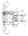
- the seat base frame 15 has a hollow fork body made of light metal casting with a base part 15.1 shown in FIG. 2 and two fork legs 15.2 and 15.3 symmetrical to a central vertical plane indicated by a dash-dotted line 21.
- the hollow fork body is largely open towards the underside shown in FIG. 2, as can also be seen in the longitudinal sections through the fork leg 15.2 shown in FIGS. 1, 6 and 7.
- the hollow base part 15.1 of the seat base frame 15 is provided with hollow-cylindrical end parts 15.4 and 15.5, some of which protrude beyond the attachment points of the fork legs.
- first horizontal pivot axis 22 mounted in the fork legs, on which the seat support 18 via supporting webs 24 extending from a mounting plate 23 on the fork body of the Seat base 15 is articulated.
- the backrest support 19 is connected in an articulated manner to the seat base frame 15 about a second horizontal axis 25, which runs within the base part 15.1 of the seat base frame 15 and is supported there in transverse walls 15.6 and 15.7 of the base part.
- the backrest support is also fork-shaped and divided into two support legs 19.1 and 19.2.
- both support legs 19.1 and 19.2 of the backrest support 19 extends a bracket 26 attached to the seat support 18, which is articulated to both support legs 19.1 and 19.2 and causes the coupling of the seat support 18 and the backrest support 19, which is remote from the two pivot axes 22 and 25.
- the backrest 20 can be clamped between the two carrier legs 19.1 and 19.2 at a desired height by means of a holding part 27 partially shown in FIG. 1.
- both support legs 19.1 and 19.2 are each provided with a slot 28 which is not open to the outside and through which a tension anchor 29 is guided. The ends of the slots 28 determine the two ends of the adjustment range for the backrest 20.
- a device for springing the backrest support is accommodated, the springing hardness of which can be adjusted on a front handwheel 30.
- a gas spring 40 is accommodated in the fork leg 15.2 of the seat base frame 15 for the backrest suspension.
- a spring body 31 made of an elastic material is arranged in the end part 15.5. The spring body 31 is between a with the support leg 19.2 rigidly connected lever 32 and a counter bearing part 33 clamped.
- the counter bearing part 33 is connected to a nut part 34 which is arranged on a screw spindle 36 which is rotatably mounted in the intermediate wall 15.7 and an end cover 35 of the seat underframe 15 and on whose one end which is guided to the outside is fastened the rotary handle 30.
- the nut part 34 By means of the nut part 34, the counter-bearing part 33 can be adjusted along an inclined surface 37 formed on the inner wall of the end part 15.5 by changing the distance between the counter-bearing part 33 and lever 32.
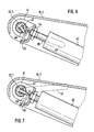
- the support leg 19.1 of the backrest support 19, which is also immersed in the base part 15.1, is provided with a side arm 38 (FIG. 2) projecting into the end part 15.4, to which the cylinder of the gas spring 40 is articulated. 2 and 6-7, the piston rod 39 of the gas spring 40 is supported on a bracket 41 which is pivotably mounted about the horizontal axis 22 in the fork leg 15.2.
- the pivot axis consists of a tube 22.1, within which an adjusting shaft 42 runs concentrically, on which an adjusting lever 43 shown in FIG. 1 is anchored.
- a concentric adjusting pin 44 is mounted in a known manner, the end of which rests against a pivot lever 45 mounted in the bracket 41.
- a cross pin 46 anchored in the actuating shaft 42 acts on the pivoting lever 45 in such a way that when the actuating lever 43 is pushed up from its position shown in broken lines in FIG. 6 into the position also shown in broken lines in FIG rotational movement of the actuating shaft 42 of the pivot lever 45 is pivoted clockwise by the cross pin 46 and thereby moves the adjusting pin 44 of the gas spring 40 inwards, whereby the gas spring is released for pivoting the backrest support.
- an actuating lever 47 is attached to an actuating shaft 48 in mirror image of the actuating lever 43 and runs coaxially to the actuating shaft 42 and the axis 22.
- the adjusting shaft 48 is coupled via a linkage 49, which is arranged inside the fork leg 15.3 and is not shown in more detail, to an adjusting shaft 50 which is mounted in the base part 15.1 of the seat base frame 15 and which carries a pivot arm 51 shown in FIG. 2, which is similar to the pivot lever 45 acts on an adjusting pin of a gas spring accommodated in the chair column 13, not shown, which serves in a known manner to spring the seat base and to adjust the height of the chair column.
Landscapes
- Health & Medical Sciences (AREA)
- Dentistry (AREA)
- General Health & Medical Sciences (AREA)
- Chairs Characterized By Structure (AREA)
Applications Claiming Priority (2)
| Application Number | Priority Date | Filing Date | Title |
|---|---|---|---|
| DE3837727 | 1988-11-07 | ||
| DE19883837727 DE3837727A1 (de) | 1988-11-07 | 1988-11-07 | Stuhl, insbesondere buerostuhl |
Publications (1)
| Publication Number | Publication Date |
|---|---|
| EP0368002A1 true EP0368002A1 (fr) | 1990-05-16 |
Family
ID=6366648
Family Applications (1)
| Application Number | Title | Priority Date | Filing Date |
|---|---|---|---|
| EP89118760A Withdrawn EP0368002A1 (fr) | 1988-11-07 | 1989-10-10 | Chaise, notamment chaise de bureau |
Country Status (2)
| Country | Link |
|---|---|
| EP (1) | EP0368002A1 (fr) |
| DE (1) | DE3837727A1 (fr) |
Cited By (3)
| Publication number | Priority date | Publication date | Assignee | Title |
|---|---|---|---|---|
| DE4324543A1 (de) * | 1993-07-22 | 1995-01-26 | Trendoffice Bueromoebel | Stuhl, insbesondere Bürostuhl |
| ES2142185A1 (es) * | 1996-02-02 | 2000-04-01 | Ind Y Fundiciones Iglesias S A | Mejoras en los sistemas reguladores del basculamiento del respaldo y asiento de butacas. |
| EP1468633A1 (fr) * | 2003-04-14 | 2004-10-20 | Vitra Patente AG | Mécanisme avec un ressort pneumatique pour une chaise avec siège et dossier synchrobasculant |
Families Citing this family (1)
| Publication number | Priority date | Publication date | Assignee | Title |
|---|---|---|---|---|
| CA2136967C (fr) | 1992-06-15 | 2001-04-03 | William E. Stumpf | Chaise de bureau |
Citations (4)
| Publication number | Priority date | Publication date | Assignee | Title |
|---|---|---|---|---|
| EP0049310A1 (fr) * | 1980-10-01 | 1982-04-14 | Wilkhahn Wilkening + Hahne GmbH + Co. | Chaise de travail |
| DE8607194U1 (de) * | 1986-03-15 | 1986-04-30 | Drabert Söhne Minden (Westf.), 4950 Minden | Sitzmöbel |
| EP0205097A2 (fr) * | 1985-06-14 | 1986-12-17 | August Fröscher GmbH & Co. K.G. | Chaise de travail |
| EP0250207B1 (fr) * | 1986-06-16 | 1992-06-10 | Mines & West Business Furniture Limited | Chaises réglables |
-
1988
- 1988-11-07 DE DE19883837727 patent/DE3837727A1/de not_active Withdrawn
-
1989
- 1989-10-10 EP EP89118760A patent/EP0368002A1/fr not_active Withdrawn
Patent Citations (4)
| Publication number | Priority date | Publication date | Assignee | Title |
|---|---|---|---|---|
| EP0049310A1 (fr) * | 1980-10-01 | 1982-04-14 | Wilkhahn Wilkening + Hahne GmbH + Co. | Chaise de travail |
| EP0205097A2 (fr) * | 1985-06-14 | 1986-12-17 | August Fröscher GmbH & Co. K.G. | Chaise de travail |
| DE8607194U1 (de) * | 1986-03-15 | 1986-04-30 | Drabert Söhne Minden (Westf.), 4950 Minden | Sitzmöbel |
| EP0250207B1 (fr) * | 1986-06-16 | 1992-06-10 | Mines & West Business Furniture Limited | Chaises réglables |
Cited By (4)
| Publication number | Priority date | Publication date | Assignee | Title |
|---|---|---|---|---|
| DE4324543A1 (de) * | 1993-07-22 | 1995-01-26 | Trendoffice Bueromoebel | Stuhl, insbesondere Bürostuhl |
| DE4324543C2 (de) * | 1993-07-22 | 2003-06-26 | Dauphin Friedrich W Gmbh | Stuhl, insbesondere Bürostuhl |
| ES2142185A1 (es) * | 1996-02-02 | 2000-04-01 | Ind Y Fundiciones Iglesias S A | Mejoras en los sistemas reguladores del basculamiento del respaldo y asiento de butacas. |
| EP1468633A1 (fr) * | 2003-04-14 | 2004-10-20 | Vitra Patente AG | Mécanisme avec un ressort pneumatique pour une chaise avec siège et dossier synchrobasculant |
Also Published As
| Publication number | Publication date |
|---|---|
| DE3837727A1 (de) | 1990-05-10 |
Similar Documents
| Publication | Publication Date | Title |
|---|---|---|
| DE3741472C2 (fr) | ||
| EP0248418B1 (fr) | Siège fonctionnel | |
| EP0179357B1 (fr) | Chaise | |
| EP0584620B1 (fr) | Chaise | |
| DE4220881C2 (de) | Stoßdämpfer für die Rückenlehne von Sitzen | |
| DE10026292C2 (de) | Stuhl | |
| EP0281749B1 (fr) | Chaise, notamment chaise de travail | |
| EP0198056B1 (fr) | Support de siege pour chaises, surtout pour des chaises de travail | |
| EP1258211B1 (fr) | Mécanisme synchronisé pour un mouvement correlé entre une siège et un dossier des chaises de bureau | |
| DE9104854U1 (de) | Stuhl, insbesondere Bürostuhl | |
| DE60309789T2 (de) | Laufrichtung eines Skateboards | |
| EP0368002A1 (fr) | Chaise, notamment chaise de bureau | |
| EP0351721A1 (fr) | Armature de suspension pour un siège ou lit | |
| DE7510478U (de) | Kipp-schwingvorrichtung fuer sitze, sessel u.dgl. | |
| DE10123231C2 (de) | Bürostuhl | |
| DE3635243C2 (de) | Stuhl, insbesondere Bürostuhl | |
| DE3200360C2 (de) | Arbeitsstuhl | |
| EP0341344B1 (fr) | Meuble servant de siège | |
| DE19848400A1 (de) | Stuhl | |
| DE3914832A1 (de) | Stuhl, insbesondere buerostuhl | |
| EP0593881A1 (fr) | Support de siège pour meubles d'assise | |
| AT225449B (de) | Mikroskop | |
| AT293666B (de) | Schaukelsessel | |
| AT401219B (de) | Vorrichtung für monitore von computeranlagen od. dgl. | |
| DE1430578C3 (de) | Fahrzeugsitz |
Legal Events
| Date | Code | Title | Description |
|---|---|---|---|
| PUAI | Public reference made under article 153(3) epc to a published international application that has entered the european phase |
Free format text: ORIGINAL CODE: 0009012 |
|
| AK | Designated contracting states |
Kind code of ref document: A1 Designated state(s): AT BE CH FR GB IT LI LU NL SE |
|
| 17P | Request for examination filed |
Effective date: 19900612 |
|
| 17Q | First examination report despatched |
Effective date: 19910819 |
|
| STAA | Information on the status of an ep patent application or granted ep patent |
Free format text: STATUS: THE APPLICATION IS DEEMED TO BE WITHDRAWN |
|
| 18D | Application deemed to be withdrawn |
Effective date: 19920303 |