EP0593881A1 - Support de siège pour meubles d'assise - Google Patents
Support de siège pour meubles d'assise Download PDFInfo
- Publication number
- EP0593881A1 EP0593881A1 EP93113793A EP93113793A EP0593881A1 EP 0593881 A1 EP0593881 A1 EP 0593881A1 EP 93113793 A EP93113793 A EP 93113793A EP 93113793 A EP93113793 A EP 93113793A EP 0593881 A1 EP0593881 A1 EP 0593881A1
- Authority
- EP
- European Patent Office
- Prior art keywords
- seat support
- rocker
- support according
- seat
- backrest
- Prior art date
- Legal status (The legal status is an assumption and is not a legal conclusion. Google has not performed a legal analysis and makes no representation as to the accuracy of the status listed.)
- Ceased
Links
Images


Classifications
-
- A—HUMAN NECESSITIES
- A47—FURNITURE; DOMESTIC ARTICLES OR APPLIANCES; COFFEE MILLS; SPICE MILLS; SUCTION CLEANERS IN GENERAL
- A47C—CHAIRS; SOFAS; BEDS
- A47C1/00—Chairs adapted for special purposes
- A47C1/02—Reclining or easy chairs
- A47C1/031—Reclining or easy chairs having coupled concurrently adjustable supporting parts
- A47C1/032—Reclining or easy chairs having coupled concurrently adjustable supporting parts the parts being movably-coupled seat and back-rest
- A47C1/03255—Reclining or easy chairs having coupled concurrently adjustable supporting parts the parts being movably-coupled seat and back-rest with a central column, e.g. rocking office chairs
-
- A—HUMAN NECESSITIES
- A47—FURNITURE; DOMESTIC ARTICLES OR APPLIANCES; COFFEE MILLS; SPICE MILLS; SUCTION CLEANERS IN GENERAL
- A47C—CHAIRS; SOFAS; BEDS
- A47C1/00—Chairs adapted for special purposes
- A47C1/02—Reclining or easy chairs
- A47C1/031—Reclining or easy chairs having coupled concurrently adjustable supporting parts
- A47C1/032—Reclining or easy chairs having coupled concurrently adjustable supporting parts the parts being movably-coupled seat and back-rest
- A47C1/03261—Reclining or easy chairs having coupled concurrently adjustable supporting parts the parts being movably-coupled seat and back-rest characterised by elastic means
- A47C1/03266—Reclining or easy chairs having coupled concurrently adjustable supporting parts the parts being movably-coupled seat and back-rest characterised by elastic means with adjustable elasticity
-
- A—HUMAN NECESSITIES
- A47—FURNITURE; DOMESTIC ARTICLES OR APPLIANCES; COFFEE MILLS; SPICE MILLS; SUCTION CLEANERS IN GENERAL
- A47C—CHAIRS; SOFAS; BEDS
- A47C1/00—Chairs adapted for special purposes
- A47C1/02—Reclining or easy chairs
- A47C1/031—Reclining or easy chairs having coupled concurrently adjustable supporting parts
- A47C1/032—Reclining or easy chairs having coupled concurrently adjustable supporting parts the parts being movably-coupled seat and back-rest
- A47C1/03205—Reclining or easy chairs having coupled concurrently adjustable supporting parts the parts being movably-coupled seat and back-rest having adjustable and lockable inclination
- A47C1/03216—Reclining or easy chairs having coupled concurrently adjustable supporting parts the parts being movably-coupled seat and back-rest having adjustable and lockable inclination by fluid means
-
- A—HUMAN NECESSITIES
- A47—FURNITURE; DOMESTIC ARTICLES OR APPLIANCES; COFFEE MILLS; SPICE MILLS; SUCTION CLEANERS IN GENERAL
- A47C—CHAIRS; SOFAS; BEDS
- A47C1/00—Chairs adapted for special purposes
- A47C1/02—Reclining or easy chairs
- A47C1/031—Reclining or easy chairs having coupled concurrently adjustable supporting parts
- A47C1/032—Reclining or easy chairs having coupled concurrently adjustable supporting parts the parts being movably-coupled seat and back-rest
- A47C1/03261—Reclining or easy chairs having coupled concurrently adjustable supporting parts the parts being movably-coupled seat and back-rest characterised by elastic means
- A47C1/03283—Reclining or easy chairs having coupled concurrently adjustable supporting parts the parts being movably-coupled seat and back-rest characterised by elastic means with fluid springs
-
- A—HUMAN NECESSITIES
- A47—FURNITURE; DOMESTIC ARTICLES OR APPLIANCES; COFFEE MILLS; SPICE MILLS; SUCTION CLEANERS IN GENERAL
- A47C—CHAIRS; SOFAS; BEDS
- A47C3/00—Chairs characterised by structural features; Chairs or stools with rotatable or vertically-adjustable seats
- A47C3/20—Chairs or stools with vertically-adjustable seats
- A47C3/30—Chairs or stools with vertically-adjustable seats with vertically-acting fluid cylinder
Definitions
- the present invention relates to a seat support for seating furniture according to the preamble of claim 1 and a seating furniture using the seat support according to the invention.
- the object of the present invention is to provide a seat support for seating furniture which enables a simple construction which is favorable in terms of production technology and which is highly user-friendly and reliable.
- the invention has only one damping member for backrest adjustment, in particular a gas spring, which interacts with a locking device provided as a complete structural unit.
- the gas spring usually has a valve which can be actuated by the locking device, the locking device being adjustable by the user via an actuating part, in particular via a handle.
- the action of the gas spring is carried out via a longitudinally displaceable pin of the locking device, which creates the possibility to easily control the locking device, namely so that only a longitudinal displacement of the pin necessary is.
- the embodiment of claims 3 and 4 have the advantage that the control of the pen is carried out only by pressurization at its free end, the locking - as in a ballpoint pen - changes with each pressurization of the pen.
- the design means that the user only ever has to operate the handle in the same way to unlock or lock the backrest.
- the object of claim 5 has the advantage that all parts connected to the handle and transmitting the rotary movement are not visible from the outside, since they run in the cross member. In addition, these parts are effectively protected against contamination. Finally, the risk of injury is reduced by avoiding parts protruding from the underside of the seat.
- the base body is preferably designed like a housing, the gas spring and its locking means being arranged within the base body.
- the base body is connected with the interposition of a rocker with the seat, which has the advantage that different rockers can be mounted, so that for example when synchronizing the movement of the backrest and the movement of the rocker of the seat different synchronization angles can be achieved depending on customer requirements .
- the inclination of the rocker changes with the inclination of the rocker for the backrest, in such a way that the rear region of the seat, which directly adjoins the backrest pivoted slightly downwards. This maintains an ergonomically favorable positioning of the backrest and seat.
- the housing of the gas spring is arranged to be longitudinally movable in the base body.
- the plunger of the gas spring can act as a fixed part, for example on the locking device, which serves as an abutment.
- a synchronization of the movement of the backrest to the rocker of the seat can also be achieved in that the rocker engages on a fastening part of the housing of the gas spring via at least one inclined or curved cam part.
- the cam surface is designed such that when the rocker arm of the backrest is pivoted backwards, due to the movement of the housing of the gas spring or its fastening part, the rocker arm swings downward on the side facing the backrest.
- the rocker is equipped with an adjustment device, in particular a spindle for any adjustment of the seat inclination
- the pivoting range of the backrest can be changed by adjusting the adjustment device or spindle, i.e. be made smaller.
- the force exerted by the spindle is transmitted to the fastening part of the gas spring via the cam surface of the rocker and causes something to be displaced longitudinally from its rest, which reduces the stroke of the gas spring.
- the object of claim 11 is particularly simple from a design point of view, since the cross bolt as a fastening part of the housing of the gas spring firstly ensures the guidance of the gas spring within the base body and secondly forms the receptacle for the cam surface of the rocker for the seat.
- a common movement from the swing arm to the backrest Swing arm of the seat can also be achieved in that the rocker arm of the seat is connected to one another via a synchronization linkage which is rotatably mounted on both sides with the cross bar and a lever arm fixedly arranged thereon.
- the synchronization linkage thus transmits the rotary movement of the crossbar and thus the swing arm of the backrest to the swing arm of the seat.
- a further embodiment of the invention in particular intended for a standard seat support model, is characterized in that the rocker arm is connected to the base body so that it does not move, so that there is no movement even when the backrest is moved.
- an additional damping element is provided for damping the movement of the backrest, to ensure effective damping even for people with a high body weight.
- the damping element is expediently designed so that when the rocker arm of the backrest is pivoted back, the damping element is compressed.
- the subject matter of claim 16 describes a structurally very simple configuration of the attenuator, which can be assembled in a simple manner and, moreover, consists of a few parts.
- the damping effect of the attenuator is also adjustable depending on the weight of the user.
- claim 18 offers a very simple possibility of constructively realizing the attenuator. In addition, assembly is particularly easy.
- the subclaims 20-24 relate to expedient configurations of the seat height adjustment, which also applies in this way it is provided that all transmission parts starting from the handle on the outside of the crossbar run inside the crossbar and are therefore not visible from the outside.
- the Bowden cable intended for power transmission is changed in its longitudinal extent via inclined planes on the handle side, which are rotated relative to one another.
- the use of two inclined planes which can be rotated relative to one another has the advantage that these parts can also be accommodated within the cross member.
- the subject matter of claim 23 offers a particularly simple possibility of ensuring a restoring force of the seat height adjustment mechanism.
- the base body is expediently designed like a housing, the gas spring, locking device, damping element and seat height adjustment mechanism being arranged for the most part within the base body and therefore not accessible or not visible from the outside. Only the transmitting parts starting from the handles arranged on both sides of the crossbars are located within the crossbars in question, which creates a very compact design.
- the basic body is designed as a module as a unitary part, so that there is the possibility of using the seat support for different chair types. Only minor modifications or adjustments are necessary.
- the base body for accommodating the individual parts can have a plurality of chambers running transversely to the two cross bars. This results in advantages in terms of assembly, for example the lateral guidance of the fastening element of the gas spring.
- the connection between the swing arm and the backrest is form-fitting on the rocker slide-on holding part is provided, which is attached to the backrest. Since the swing arm of the backrest tapers towards the top, the holding part can be pushed downward onto the swing arm if the holding part is designed analogously.
- a device for quick locking is expediently provided for connecting the parts.
- the invention also relates to seating furniture with a seat, a backrest, a foot extension and a foot frame using the seat support according to the invention according to at least one of claims 1-27.
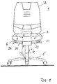
- Reference number 1 denotes an office swivel chair using the seat body according to the invention.
- the office swivel chair comprises a backrest 2, a seat 3 and a housing-like base body 8 which merges into a foot extension 4 which is preferably telescopic.
- a foot extension 4 which is preferably telescopic.
- Two cross bars 30, 31 open into the respective side area of the base body 8 and are pivotably mounted in the latter.
- the two cross bars 30, 31 form part of the rocker arm 6, which supports the backrest 2.
- a spindle 15 or 53 for setting the damping of the backrest 2 desired by the user and the pivoting position and pivoting movement of the seat 3. This will also be explained in more detail below.
- the cross member 31 is connected in a rotationally fixed manner to two lever arms, the lever arms being arranged on both sides of the housing 20 of a locking device.
- the two lever arms are provided in order to transmit the pivoting movement of the backrest 6 to a gas spring 16 in the interior of the base body 8.
- two actuating arms are provided, which on the one hand with the respective lever arm e.g. 12 are pivotally connected and act on a transverse pin 26 at their opposite end.
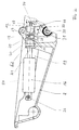
- the rear actuating arm 19 is shown in FIG. 2.
- the cross pin 26 extends transversely through a head region of the housing 24 of the gas spring 16 and through the two actuating arms and is guided in two longitudinal holes 38, 39 on the housing of the base body 8 (cf. also FIG. 4).
- the housing 20 of the locking device is connected to the base body 8 in a manner fixed against movement.
- the locking device forms a complete component, as it were.
- the housing 20 of the locking device serves as an abutment for the stamp 21 the gas spring 16.
- the construction causes that when pivoting the backrest 6, i.e. Swiveling the crossbar 30 over the lever arms e.g. 12, the operating arms e.g. 19 the housing 24 of the gas spring 16 is moved in the longitudinal direction when the plunger 21 is stationary, which enables the backrest to be pivoted gently backwards when the valve (not shown) of the gas spring 16 is open.
- the gas present in the gas spring 16 is compressed, so that the backrest automatically returns to its starting position when the load is released.
- the inclination range of the backrest 2 is normally between approximately 95 ° and 111 °.
- a longitudinally displaceable and cross-rotatable pin 47 is provided which passes through the housing 20 of the locking device and the stamp 21. Depending on the longitudinal position of the pin 47, the open or closed position of the gas spring 16 is set via the valve.
- a rotatably mounted lever arm 34 is provided, which is controlled by a cam 33 connected to a shaft 32 guided in the interior of the cross member 30.
- the handle for actuating the shaft 32 and thus the pin 47 is, as shown in FIG. 1, at the end of the associated cross member.
- the respective axial position of the pin 47 is determined by a control part 29 which has recesses 23 of different depths; 28, into which a projection 46 of a ring 48 connected to the housing 20 engages.
- the two different depths of the recesses provided in the control part ensure two different axial longitudinal positions of the pin 47.
- the inclined planes 22, for example Serrations interact with the inclined planes 27 of the control part in such a way that when the pin 47 and thus the control part 29 are axially displaced, the latter is rotated slightly, so that the projection 46 of the ring 48 when springing back, i. when the pin 47 is relieved via the lever arm 34 into the next recess e.g. 23 engages.
- the restoring force on the pin 47 is ensured by a spring or the like which is not shown in FIG. 2 for the sake of clarity.
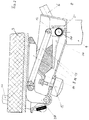
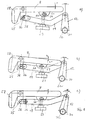
- Fig. 3 shows an embodiment of the seat support according to the invention, in which there is a synchronization between the movement of the backrest and the seat inclination.
- the seat support has a one-piece rocker arm 9, each of which is pivotably connected to the base body 8, in particular screwed, via two support arms, of which only the support arm 62 is shown in FIG. 3.
- This rocker is connected via a synchronization linkage 11 in the form of a double-articulated connecting rod to a lever arm 12 on the cross member 30. If, for example, the backrest is pivoted backwards, then the rocker arm 9 swivels slightly via the synchronization linkage 11, thereby maintaining an ergonomically favorable arrangement between the seat 3 and the backrest 2 even when the backrest 2 is pivoted backwards can be.
- FIG. 3 there is also an attenuator 13 in the form of a block of elastic material e.g. elastic polyurethane foam recognizable.
- the block 27 rests on its underside on a lever arm 34 which is connected to the cross bar 30.
- a spring plate 14 which is fastened in the region of the base body 8 facing the cross member 31, comprises the block and is held at the opposite point by means of a spindle 15 arranged on the underside of the base body 8.
- a gas spring (not shown) provided in the foot extension 4, which is also controlled via a pin 50 running in the foot extension 4.
- a pivotably mounted lever arm 40 in the form of an angle is provided within the base body 8, the angle section of which is connected to a Bowden cable 42.
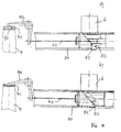
- the Bowden cable 42 is actuated via two inclined planes 51, 52 accommodated in the cross member 30, which lie against one another in the normal state (passive position) (FIG. 4 a)), when pivoting the inclined plane 52 with respect to the inclined plane 51 by the handle 36, however, experience a displacement such that the part of the inclined plane 52 in question, which is connected to the Bowden cable 42, is pressed outwards, as a result of which the lever arm 40 is actuated and the pin 15 moves axially. The valve is then open, so the seat height can be adjusted.
- a layer of elastic polyurethane foam is provided, which provides the necessary restoring force.
- Fig. 5 shows the arrangement of the individual components within the base body 8.
- the base body 8 is constructed like a housing and has three chambers 43, 44 and 45, which run transversely to the two spars 30, 31 and through two central struts 27; 35 are formed.
- the gas spring 16 and the locking device are located in the chamber 43 arranged on the left in FIG. 5.
- the damper 13 and the synchronization rod 11 connected to the rocker 9, not shown, are located in the chamber 45 arranged on the right.
- the lever arm 40 of the seat height adjustment mechanism is arranged, which via a disk-shaped part 41 made of elastic material, e.g. elastic polyurethane foam acts on the pin to open or close the gas spring housed in the foot extension.
- elastic material e.g. elastic polyurethane foam
- a holding part 54 is screwed to the backrest 2 according to FIG. 6.
- the holding part 54 comprises two laterally arranged Projections 55, which partially enclose the rocker 6. For the sake of clarity, only one side of the holding part 54 is provided with the reference number 55.
- the backrest 2 is pushed together with the holding part 54 onto the rocker arm 6, which tapers upwards and is secured via a snap connection 56.
- Fig. 7 shows two positions of an embodiment of the seat support, in which the rocker 9 of the seat is rigid.
- the actuating arm 19 is consequently pulled forward, this movement being transmitted to the housing of the gas spring 16 via the cross bolt 26.
- the guidance takes place via the transverse bolt 26, which is arranged to be longitudinally displaceable within the two elongated holes 38, 39.
- the backrest and the seat are not synchronized in this embodiment.
- FIG. 8 shows the configuration of the seat support using the synchronization linkage 11. If the backrest is pivoted backwards from its basic position according to FIG. 8 a), the synchronization linkage 11 causes the rocker 9 for the seat 2 to pivot slightly (FIG. 8 b). ) in a range from -1 ° to 6 ° based on the horizontal. At the same time, the synchronization also means that when the seat is loaded, i.e. the swing arm 9 a slight pivoting caused by this is transmitted to the swing arm 6 and thus to the backrest 2.
- FIG. 9 shows a further embodiment of the seat support according to the invention, in which the seat inclination can additionally be adjusted by hand using a spindle 53.
- the synchronization of the movement of the rocker 9 of the seat with the movement of the rocker 6 of the backrest 2 takes place via two inclined cam surfaces of the rocker 9, which rest on the top of the cross pin 26.
- the cam surface 25 is shown in Fig. 9.
- the cam surfaces alone synchronize the movement from the backrest to the seat. This is because the backrest is pivoted backwards, the housing of the gas spring being pulled forward via the two actuating arms and the transverse bolt, so that the rocker arm swings slightly for the seat.
- a holding part 61 is provided on the underside of the rocker 9, which serves as an abutment for a spindle 53 provided on the underside of the base body 8.
- the spindle is held in the holding part via a cross pin 60, which is positioned within a longitudinal hole 59.
Landscapes
- Health & Medical Sciences (AREA)
- Dentistry (AREA)
- General Health & Medical Sciences (AREA)
- Chairs Characterized By Structure (AREA)
- Chairs For Special Purposes, Such As Reclining Chairs (AREA)
Applications Claiming Priority (2)
| Application Number | Priority Date | Filing Date | Title |
|---|---|---|---|
| DE4235435 | 1992-10-21 | ||
| DE4235435A DE4235435A1 (de) | 1992-10-21 | 1992-10-21 | Sitzträger für Sitzmöbel |
Publications (1)
| Publication Number | Publication Date |
|---|---|
| EP0593881A1 true EP0593881A1 (fr) | 1994-04-27 |
Family
ID=6470949
Family Applications (1)
| Application Number | Title | Priority Date | Filing Date |
|---|---|---|---|
| EP93113793A Ceased EP0593881A1 (fr) | 1992-10-21 | 1993-08-28 | Support de siège pour meubles d'assise |
Country Status (2)
| Country | Link |
|---|---|
| EP (1) | EP0593881A1 (fr) |
| DE (1) | DE4235435A1 (fr) |
Cited By (3)
| Publication number | Priority date | Publication date | Assignee | Title |
|---|---|---|---|---|
| KR100623831B1 (ko) | 2003-11-18 | 2006-09-19 | 수스파 홀딩 게엠베하 | 길이 조정가능한 압축 스프링 |
| US10881208B2 (en) * | 2016-02-23 | 2021-01-05 | Kokuyo Co., Ltd. | Chair and seat support mechanism |
| CN113197456A (zh) * | 2021-01-13 | 2021-08-03 | 安吉万宝智能家居科技有限公司 | 一种多功能座椅 |
Families Citing this family (1)
| Publication number | Priority date | Publication date | Assignee | Title |
|---|---|---|---|---|
| DE202017100480U1 (de) * | 2017-01-30 | 2018-05-03 | Armin Sander | Sitzmöbel, insbesondere Bürostuhl |
Citations (6)
| Publication number | Priority date | Publication date | Assignee | Title |
|---|---|---|---|---|
| FR1298474A (fr) * | 1961-05-20 | 1962-07-13 | Siège perfectionné | |
| DE2925520A1 (de) * | 1979-06-25 | 1981-01-15 | Mauser Waldeck Gmbh | Drehsessel |
| EP0052832A2 (fr) * | 1980-11-21 | 1982-06-02 | Protoned B.V. | Tête de commande pour ressort pneumatique, notamment pour le réglage de sièges de meubles d'assise |
| EP0126839A1 (fr) * | 1983-05-10 | 1984-12-05 | Meiko Industrial Co., Ltd. | Chaise à appui |
| EP0263323A2 (fr) * | 1986-10-07 | 1988-04-13 | Inaba Seisakusho Co., Ltd. | Meuble pour s'asseoir |
| EP0283170A1 (fr) * | 1987-03-14 | 1988-09-21 | PHR Furniture Limited | Chaises à colonne |
-
1992
- 1992-10-21 DE DE4235435A patent/DE4235435A1/de not_active Withdrawn
-
1993
- 1993-08-28 EP EP93113793A patent/EP0593881A1/fr not_active Ceased
Patent Citations (6)
| Publication number | Priority date | Publication date | Assignee | Title |
|---|---|---|---|---|
| FR1298474A (fr) * | 1961-05-20 | 1962-07-13 | Siège perfectionné | |
| DE2925520A1 (de) * | 1979-06-25 | 1981-01-15 | Mauser Waldeck Gmbh | Drehsessel |
| EP0052832A2 (fr) * | 1980-11-21 | 1982-06-02 | Protoned B.V. | Tête de commande pour ressort pneumatique, notamment pour le réglage de sièges de meubles d'assise |
| EP0126839A1 (fr) * | 1983-05-10 | 1984-12-05 | Meiko Industrial Co., Ltd. | Chaise à appui |
| EP0263323A2 (fr) * | 1986-10-07 | 1988-04-13 | Inaba Seisakusho Co., Ltd. | Meuble pour s'asseoir |
| EP0283170A1 (fr) * | 1987-03-14 | 1988-09-21 | PHR Furniture Limited | Chaises à colonne |
Cited By (4)
| Publication number | Priority date | Publication date | Assignee | Title |
|---|---|---|---|---|
| KR100623831B1 (ko) | 2003-11-18 | 2006-09-19 | 수스파 홀딩 게엠베하 | 길이 조정가능한 압축 스프링 |
| US10881208B2 (en) * | 2016-02-23 | 2021-01-05 | Kokuyo Co., Ltd. | Chair and seat support mechanism |
| CN113197456A (zh) * | 2021-01-13 | 2021-08-03 | 安吉万宝智能家居科技有限公司 | 一种多功能座椅 |
| CN113197456B (zh) * | 2021-01-13 | 2023-11-21 | 安吉万宝智能家居科技有限公司 | 一种多功能座椅 |
Also Published As
| Publication number | Publication date |
|---|---|
| DE4235435A1 (de) | 1994-04-28 |
Similar Documents
| Publication | Publication Date | Title |
|---|---|---|
| DE4220881C2 (de) | Stoßdämpfer für die Rückenlehne von Sitzen | |
| EP0638265B1 (fr) | Chaise de bureau | |
| DE8205761U1 (de) | Sitzmoebel | |
| CH636252A5 (de) | Ergonomischer stuhl. | |
| DE3429186A1 (de) | Sitzmoebel, insbesondere buerostuhl | |
| DE202010013146U1 (de) | Schwingsessel | |
| DE8217774U1 (de) | Stuhl | |
| DE3534496A1 (de) | Sitzmoebel | |
| EP0198056B1 (fr) | Support de siege pour chaises, surtout pour des chaises de travail | |
| DE2820064A1 (de) | Sitzhalterung fuer sessel | |
| EP3120732B1 (fr) | Mecanisme de siege de bureau | |
| DE69208275T2 (de) | Mechanische Vorrichtung, insbesondere für das Bewegen und selektive Verriegeln von Stühlen | |
| DE2623024A1 (de) | Sitzmoebel, insbesondere stuhl mit sitzteil | |
| DE10126000A1 (de) | Synchronmechanik für die simultane Sitzflächen- und Rückenlehnen-Schwenkbewegung bei Bürostühlen | |
| WO2006136400A1 (fr) | Accoudoir destine a un siege de vehicule et siege de vehicule | |
| DE20307191U1 (de) | Stützvorrichtung für Kleinkinder mit einem Rückenstützen/Kopfstützen-Betätigungsmechanismus | |
| DE8435615U1 (de) | Buerosessel mit hoehenverstellung und einstellbarer schwingvorrichtung | |
| EP0593881A1 (fr) | Support de siège pour meubles d'assise | |
| EP0341344B1 (fr) | Meuble servant de siège | |
| DE10123231C2 (de) | Bürostuhl | |
| DE10220841B4 (de) | Stuhl mit Rückenlehne, die zur Einstellung der Sitztiefe relativ gegenüber dem Sitzteil verstellbar ist | |
| EP3649893A1 (fr) | Reglage de la resistance au pivotement d'un composant d'un meuble | |
| DE69714910T2 (de) | Verstellvorrichtung | |
| AT402592B (de) | Vorrichtung zum abstützen einer arbeitsplatte vorrichtung zum abstützen einer arbeitsplatte | |
| EP0056454A2 (fr) | Meuble d'assise, notamment chaise tournante de bureau |
Legal Events
| Date | Code | Title | Description |
|---|---|---|---|
| PUAI | Public reference made under article 153(3) epc to a published international application that has entered the european phase |
Free format text: ORIGINAL CODE: 0009012 |
|
| AK | Designated contracting states |
Kind code of ref document: A1 Designated state(s): ES FR NL |
|
| 17P | Request for examination filed |
Effective date: 19940408 |
|
| 17Q | First examination report despatched |
Effective date: 19950712 |
|
| GRAG | Despatch of communication of intention to grant |
Free format text: ORIGINAL CODE: EPIDOS AGRA |
|
| 18R | Application refused |
Effective date: 19970217 |