EP0368033B1 - Dispositif de réglage des brûleurs à gaz par impulsion d'un four tunnel - Google Patents
Dispositif de réglage des brûleurs à gaz par impulsion d'un four tunnel Download PDFInfo
- Publication number
- EP0368033B1 EP0368033B1 EP89119189A EP89119189A EP0368033B1 EP 0368033 B1 EP0368033 B1 EP 0368033B1 EP 89119189 A EP89119189 A EP 89119189A EP 89119189 A EP89119189 A EP 89119189A EP 0368033 B1 EP0368033 B1 EP 0368033B1
- Authority
- EP
- European Patent Office
- Prior art keywords
- burner
- gas
- burners
- pulse
- gas pulse
- Prior art date
- Legal status (The legal status is an assumption and is not a legal conclusion. Google has not performed a legal analysis and makes no representation as to the accuracy of the status listed.)
- Expired - Lifetime
Links
- 238000010304 firing Methods 0.000 claims abstract description 19
- 230000001105 regulatory effect Effects 0.000 claims abstract description 6
- 239000000919 ceramic Substances 0.000 claims abstract description 5
- 230000001276 controlling effect Effects 0.000 claims abstract description 3
- 238000002485 combustion reaction Methods 0.000 description 3
- 230000004913 activation Effects 0.000 description 2
- 238000004952 furnace firing Methods 0.000 description 2
- 239000000463 material Substances 0.000 description 2
- 238000000465 moulding Methods 0.000 description 2
- 238000006243 chemical reaction Methods 0.000 description 1
- 230000001419 dependent effect Effects 0.000 description 1
- 238000010438 heat treatment Methods 0.000 description 1
- 230000003287 optical effect Effects 0.000 description 1
- 230000035515 penetration Effects 0.000 description 1
- 238000010926 purge Methods 0.000 description 1
- 230000011664 signaling Effects 0.000 description 1
- 208000011726 slow pulse Diseases 0.000 description 1
- 230000002123 temporal effect Effects 0.000 description 1
Images
Classifications
-
- F—MECHANICAL ENGINEERING; LIGHTING; HEATING; WEAPONS; BLASTING
- F27—FURNACES; KILNS; OVENS; RETORTS
- F27D—DETAILS OR ACCESSORIES OF FURNACES, KILNS, OVENS OR RETORTS, IN SO FAR AS THEY ARE OF KINDS OCCURRING IN MORE THAN ONE KIND OF FURNACE
- F27D99/00—Subject matter not provided for in other groups of this subclass
- F27D99/0001—Heating elements or systems
- F27D99/0033—Heating elements or systems using burners
-
- F—MECHANICAL ENGINEERING; LIGHTING; HEATING; WEAPONS; BLASTING
- F27—FURNACES; KILNS; OVENS; RETORTS
- F27B—FURNACES, KILNS, OVENS OR RETORTS IN GENERAL; OPEN SINTERING OR LIKE APPARATUS
- F27B9/00—Furnaces through which the charge is moved mechanically, e.g. of tunnel type; Similar furnaces in which the charge moves by gravity
- F27B9/30—Details, accessories or equipment specially adapted for furnaces of these types
- F27B9/40—Arrangements of controlling or monitoring devices
-
- F—MECHANICAL ENGINEERING; LIGHTING; HEATING; WEAPONS; BLASTING
- F27—FURNACES; KILNS; OVENS; RETORTS
- F27D—DETAILS OR ACCESSORIES OF FURNACES, KILNS, OVENS OR RETORTS, IN SO FAR AS THEY ARE OF KINDS OCCURRING IN MORE THAN ONE KIND OF FURNACE
- F27D19/00—Arrangements of controlling devices
-
- F—MECHANICAL ENGINEERING; LIGHTING; HEATING; WEAPONS; BLASTING
- F23—COMBUSTION APPARATUS; COMBUSTION PROCESSES
- F23C—METHODS OR APPARATUS FOR COMBUSTION USING FLUID FUEL OR SOLID FUEL SUSPENDED IN A CARRIER GAS OR AIR
- F23C2205/00—Pulsating combustion
- F23C2205/10—Pulsating combustion with pulsating fuel supply
-
- F—MECHANICAL ENGINEERING; LIGHTING; HEATING; WEAPONS; BLASTING
- F27—FURNACES; KILNS; OVENS; RETORTS
- F27D—DETAILS OR ACCESSORIES OF FURNACES, KILNS, OVENS OR RETORTS, IN SO FAR AS THEY ARE OF KINDS OCCURRING IN MORE THAN ONE KIND OF FURNACE
- F27D99/00—Subject matter not provided for in other groups of this subclass
- F27D99/0001—Heating elements or systems
- F27D99/0033—Heating elements or systems using burners
- F27D2099/0043—Impulse burner
-
- F—MECHANICAL ENGINEERING; LIGHTING; HEATING; WEAPONS; BLASTING
- F27—FURNACES; KILNS; OVENS; RETORTS
- F27M—INDEXING SCHEME RELATING TO ASPECTS OF THE CHARGES OR FURNACES, KILNS, OVENS OR RETORTS
- F27M2001/00—Composition, conformation or state of the charge
- F27M2001/15—Composition, conformation or state of the charge characterised by the form of the articles
- F27M2001/1504—Ceramic articles
Definitions
- the invention relates to a device for controlling gas pulse burners of a tunnel furnace, according to the preamble of claim 1.
- the kiln car stock requires, i.e. the material to be burned (furnace material) stacked on a kiln car, which can be moved in cycles through a tunnel furnace, viewed in the furnace cross section, partially different heat input, in order to ultimately ensure uniform heating of all the ceramic moldings to be fired.
- a device of the generic type has become known several times in practice - namely by a gas pulse burner control system with the switching unit of the "GI-12" type from the KELLER group of companies from D-4530 Ibbenbüren-Laggenbeck.
- This known control device is designed in such a way that the gas is supplied in pulses into the combustion zone areas in which gas auto-ignition is ensured, and that the furnace cross-section corresponds to that a "flame profile" (or “firing profile”) for each burner group as well as the burning duration, ie the time when the gas supply is switched on, can be set within each interval of the individual gas pulse burners.
- "Flame profile” is understood to mean the curve in the furnace cross section on which the flames of all gas pulse burners used are during the burner group activation.
- the gas pressure is adjustable.
- a gas supply with low and high pressure can take place alternately, in which case (each) the gas pulse burner acts one time in the upper area of the trim and the other time in the lower area of the trim and thus a better temperature distribution over the cross-sectional height of the trim (the so-called . "Stocking height") is achieved.
- the pulse time and interval time can be set independently of one another in the known gas pulse burner control, a correction of the pulse time is necessary in order to obtain a certain "burner output" when the interval time is changed.
- the pulse time gas burner pulse time
- the gas pulse burner is thus switched on 60 x 0.5 seconds per minute (i.e. in operation). If the interval / cycle time is set to 2 seconds, this results in 30 pulses per minute. 30 The or each gas pulse burner would then be switched on without changing the pulse time 30 x 0.5 sec., Which means a total of 15 sec.
- the invention is therefore based on the object of providing an improved gas pulse burner control for tunnel furnaces which enables the required temperatures in the individual regions of the furnace cross section to be set in a simple and rapid manner and thereby ensures a non-reactive setting.
- the setting of the output results in largely non-reactive setting work - as is known, only a certain burner output is required for a specific firing result. Since, in the device according to the invention, the burner output per burner is adjusted on the one hand as a fraction of the interval (ie percentage of the operating time) and, on the other hand, the pulses per minute are adjusted jointly (ie centrally) for all pulse burners, an automatic correction of the pulse time results when the pulse number changes individual gas pulse burner, because the burner output is specified and maintained.
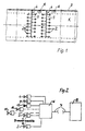
- a tunnel furnace 1 according to the invention is provided in particular for firing ceramic products and is equipped with a plurality of burner groups in the firing zone.
- Each burner group comprises a large number, for example max. 15, gas pulse burner 2.
- These gas pulse burners 2 of each burner group are preferably arranged on the tunnel furnace 1, acting from above.
- the gas pulse burners 2 are designed in accordance with DE-PS 35 13 820, i.e. equipped with a gas supply and an air supply, so that air can be pressed through the lance body between the gas impulses.
- the burner system can be provided for reducing burning.
- a gas supply main valve 4 can be connected by a gas line 3 with the interposition of each branch off a main gas line, numbered 5, for each burner group.
- each burner group preferably extend on both sides of this main gas line 5. In addition, they can be offset from one another when viewed in the width direction of the tunnel furnace 1, i.e. lie on a zigzag line (see FIG. 1).
- each burner group has an odd number of gas pulse burners 2 - the side gas pulse burners lie one behind the other in the longitudinal direction of the tunnel furnace, and the rest are arranged in a gap in the width of the tunnel furnace.
- connection and setting device 6 As can be seen from FIG. 2, all function control elements of a gas pulse burner group are connected to a connection and setting device 6, from which a multi-core, preferably 10-core cable 7 leads to a controller unit 8.
- the connection and setting device 6 is equipped with a microprocessor, not shown. This microprocessor is used to calculate and comply with the values to be observed for optimal firing of the ceramic moldings - it is able to switch / control the respective preselected burner output regardless of the set number of pulses (number of pulses per minute).
- connection and setting device 6 is advantageously located in the vicinity of the respective burner group, so that only short distances from this connection and setting device to the individual gas pulse burners are available.
- the connection and setting device 6 can be arranged at a short distance next to the tunnel furnace 1 or even above the same.
- the individual gas valves of the gas pulse burner 2 can be switched electrically, in particular by means of an electromagnetic valve.
- At least some, preferably all, gas pulse burners 2 of the tunnel furnace firing zone can be operated with at least two pressure stages, so that the gas which is supplied periodically and in pulses is one time (ie at low gas pressure) in the upper region of the stocking and the other time (ie at high pressure) Gas pressure) ignites in the lower area of the firing flame - due to self-ignition due to sufficiently high temperature.
- the solenoid valves of a main valve 4, a valve 9 for switching the second pressure stage of the gas pulse burner 2, possibly a purge air valve 10 and possibly a reduction valve 11 are connected to the connection and setting device.
- a pressure switch 12 is connected to the connection and setting device 6.
- connection and setting device 6 is installed in a stable housing with a separately accessible connection space. All setting and signaling elements required for operation are clearly arranged and advantageously user-friendly on the front panel behind a viewing window.
- the participation time (reduction time) per pressure level can be set separately (for example 10-300 milliseconds).
- the configuration switches which can only be set when a burner group is started up, are preferably located inside the device 6. A clear arrangement and good adjustability is also provided here. Specifically, the number of burners in the group is set and each gas pulse burner 2 involved in the reduction is released.
- each gas pulse burner group is housed as a compact control unit in the connection and setting device, numbered 6. This control unit switches on up to 15 gas pulse burners 2 in succession. Each gas pulse burner 2 remains switched on for a time calculated from the preselected number of pulses and the burner on time.
- This power is maintained at all times and always corresponds to the preselected duty cycle (e.g. 0 - 70% of 1 cycle / interval), even if the pulse frequency changes due to automatic (especially initiated by the microprocessor) change in the pulse length.
- the preselected duty cycle e.g. 0 - 70% of 1 cycle / interval
- the pulse length results from the following calculation:
- All gas pulse burners 2 are started in succession and remain switched on for the calculated time.
- the time offset between switching on the individual gas pulse burners 2 depends on the number of gas pulse burners 2 used and is calculated as follows:
- Any flame profile can be set using the furnace cross-section.
- the burner output is independent of the set number of pulses per minute.
- the number of pulses per minute can be used to set the flame depending on the height of the stock (i.e. according to the requirements which depend on the height of the fired goods / stock stacked on the kiln car).
- the dependence of the burner output on the pressure is, in a particularly preferred embodiment, determined by a factor (multiplier 1-2) for the lower one Equalized pressure.
- the height of the flame profile is shifted as a whole (almost a parallel shift of the flame or firing profile over the furnace cross-section height).
- the setting of the burner group is very simple because the individual settings can be carried out largely without reaction.
- the control unit according to the invention an optimal equalization of the fire in the tunnel furnace firing zone can be achieved.
- each burner group there is a temperature sensor (thermocouple or optical pyrometer) for a two-point controller. This switches the control unit of the device numbered 6 with a slow pulse-pause ratio on and off. This controls the desired temperature in the firing zone.
- a temperature sensor thermocouple or optical pyrometer
- a special feature of the control device is that the duty cycle of each gas pulse burner 2 is switched as a fraction of an interval / cycle and can be regulated.
- Another special feature is that at least some of the gas pulse burners 2 can be operated with at least 2 stages and the switching time and / or frequency of the gas supply can be regulated separately.
- control circuit (not shown, but can be understood by the person skilled in the art on the basis of the functional description) is that at least some, preferably all, gas pulse burners 2 of a burner group can be operated with at least two pressure stages and the duty cycle of the same in one pressure stage by means of a factor - i.e. a percentage change - is changeable; in a particularly preferred manner there is a circuit arrangement according to which the duty cycle can be extended in the low pressure stage.
- a time setting for pressure level 1 and pressure level 2 can be provided so that the burning time can be set separately in the upper and lower firing range.
Landscapes
- Engineering & Computer Science (AREA)
- Mechanical Engineering (AREA)
- General Engineering & Computer Science (AREA)
- Regulation And Control Of Combustion (AREA)
- Fluidized-Bed Combustion And Resonant Combustion (AREA)
- Control Of Combustion (AREA)
Claims (10)
- Dispositif (dispositif de commande) pour la commande de brûleurs à gaz à impulsions d'un four tunnel, servant à la calcination de produits céramiques (briques crues), avec plusieurs groupes de brûleurs dans la zone de calcination, chaque groupe de brûleurs présentant plusieurs brûleurs à gaz à impulsions devant être mis en circuit les uns après les autres, c'est-à-dire des brûleurs à gaz avec une amenée de gaz commutée électriquement (mise en circuit) selon des intervalles (cycles) et le dispositif de commande commutant en fonction des brûleurs à gaz individuels selon une cadence pouvant être prédéterminée, et les longueurs d'impulsions de l'amenée de gaz respective (mise en circuit du brûleur) et la pression de gaz pouvant être réglées,
caractérisé par une commande de brûleurs à gaz à impulsions avec microprocesseur permettant un débit de brûleur à respecter, avec laquelle la durée de mise en circuit de chacun des brûleurs à gaz (2) peut être régulée (réglée) en tant qu'une fraction d'intervalle indépendamment du nombre d'impulsions par minute et chaque brûleur à gaz à impulsions (2) reste (est) mis en circuit pour une durée calculée à partir d'un nombre d'impulsions et d'une durée de mise en circuit du brûleur choisis à l'avance. - Dispositif selon la revendication 1,
caractérisé en ce qu'au moins quelques-uns des brûleurs à gaz à impulsions (2) peuvent être exploités à au moins deux degrés de pression (P1, P2) et la durée de mise en circuit et/ou la fréquence de l'amenée de gaz sont en outre réglables séparément. - Dispositif selon la revendication 2,
caractérisé en ce que la durée de calcination dans la zone de calcination supérieure, c'est-à-dire à un degré de pression basse (P1), et dans la zone de calcination inférieure, c'est-à-dire à un degré de pression haute (P2), est réglable séparément. - Dispositif selon l'une des revendications 1 à 3,
caractérisé en ce que(a) les brûleurs à gaz à impulsions (2) peuvent être exploités à au moins deux degrés de pression (P1, P2) et la durée de mise en circuit et/ou la fréquence de l'amenée de gaz sont en outre réglables séparément et(b) la durée de calcination dans la zone de calcination supérieure, c'est-à-dire à un degré de pression basse (P1), et dans la zone de calcination inférieure, c'est-à-dire à un degré de pression haute (P2), est réglable séparément. - Dispositif selon l'une des revendications 1 à 4,
caractérisé en ce qu'au moins quelques-uns des brûleurs à gaz à impulsions (2) peuvent être exploités à au moins deux degrés de pression (P1, P2), la durée de mise en circuit des brûleurs à gaz à impulsions (2) peut à un degré de pression, être modifiée au moyen d'un facteur réglable - c'est-à-dire une valeur de modification selon un pourcentage. - Dispositif selon la revendication 5,
caractérisé par un ensemble de commutation selon lequel la durée de mise en circuit des brûleurs à gaz à impulsions (2) pouvant être exploités à au moins deux degrés de pression (P1, P2) peut être prolongée à l'état de pression basse (P1). - Dispositif selon au moins l'une des revendications 1 à 6,
caractérisé en ce que chaque groupe de brûleurs est raccordé à un appareil de raccordement et de réglage (6) duquel un câble multifilaire (7) conduit à une unité de régulation (8). - Dispositif selon la revendication 7,
caractérisé en ce que l'appareil de raccordement et de réglage (6) englobe tous les éléments de commande fonctionnelle pour un groupe de brûleurs à gaz à impulsions. - Dispositif selon au moins une des revendications précédentes,
caractérisé en ce que l'unité de raccordement et de réglage (6) de chaque groupe de brûleurs est disposée au voisinage de ce groupe de brûleurs. - Dispositif selon au moins une des revendications précédentes,
caractérisé en ce que celui-ci est formé pour la calcination réductrice.
Priority Applications (1)
| Application Number | Priority Date | Filing Date | Title |
|---|---|---|---|
| AT89119189T ATE89396T1 (de) | 1988-10-17 | 1989-10-16 | Vorrichtung zur steuerung von gasimpulsbrennern eines tunnelofens. |
Applications Claiming Priority (2)
| Application Number | Priority Date | Filing Date | Title |
|---|---|---|---|
| DE3835362 | 1988-10-17 | ||
| DE3835362A DE3835362A1 (de) | 1988-10-17 | 1988-10-17 | Vorrichtung zur steuerung von gasimpulsbrennern eines tunnelofens |
Publications (2)
| Publication Number | Publication Date |
|---|---|
| EP0368033A1 EP0368033A1 (fr) | 1990-05-16 |
| EP0368033B1 true EP0368033B1 (fr) | 1993-05-12 |
Family
ID=6365320
Family Applications (1)
| Application Number | Title | Priority Date | Filing Date |
|---|---|---|---|
| EP89119189A Expired - Lifetime EP0368033B1 (fr) | 1988-10-17 | 1989-10-16 | Dispositif de réglage des brûleurs à gaz par impulsion d'un four tunnel |
Country Status (3)
| Country | Link |
|---|---|
| EP (1) | EP0368033B1 (fr) |
| AT (1) | ATE89396T1 (fr) |
| DE (2) | DE3835362A1 (fr) |
Cited By (1)
| Publication number | Priority date | Publication date | Assignee | Title |
|---|---|---|---|---|
| CN111237754A (zh) * | 2020-01-15 | 2020-06-05 | 山东大学 | 一种能够燃用多组分燃料的微火焰阵列燃烧器 |
Families Citing this family (8)
| Publication number | Priority date | Publication date | Assignee | Title |
|---|---|---|---|---|
| JP2677514B2 (ja) * | 1994-03-28 | 1997-11-17 | 日本碍子株式会社 | バーナの燃焼制御方法 |
| JP3022195B2 (ja) * | 1994-09-05 | 2000-03-15 | 日本碍子株式会社 | セラミック成形体の焼成法およびそれに用いる燃焼装置 |
| DE19512633C1 (de) * | 1995-04-05 | 1996-10-17 | Heimsoth Keramische Oefen Und | Verfahren zur Steuerung der Brenner eines Herdwagenofens |
| NL1000909C1 (nl) * | 1995-08-01 | 1995-11-10 | Flynn Controls B V | Temperatuurregelaar voor een tunneloven. |
| JP3138656B2 (ja) * | 1997-03-28 | 2001-02-26 | 日本碍子株式会社 | セラミック成形体の焼成方法 |
| NL1017448C2 (nl) * | 2001-02-26 | 2002-08-27 | Nederlandse Gasunie Nv | Ovenregeling voor warmtebehandeling van producten. |
| DE102012002784A1 (de) * | 2012-02-15 | 2013-08-22 | Outotec Oyj | Verfahren zur Regelung der Brennstoffzufuhr zu Brennern einer Brennergruppe und Brennerregler |
| CN121297488A (zh) * | 2025-09-05 | 2026-01-09 | 佛山市安然热工机电设备有限公司 | 单边脉冲加单点微调平衡燃烧控制方法、系统及窑炉 |
Family Cites Families (5)
| Publication number | Priority date | Publication date | Assignee | Title |
|---|---|---|---|---|
| DE1127525B (de) * | 1960-05-28 | 1962-04-12 | Manfred Leisenberg | Einrichtung zur elektrischen Impulsregelung fuer OElbrenner von keramischen OEfen |
| CH461010A (de) * | 1967-12-08 | 1968-08-15 | Aebi Robert Ag | Impulsölfeuerung für Industrieöfen, insbesondere für die Ziegel- und Keramikindustrie |
| AT287565B (de) * | 1968-07-24 | 1971-01-25 | Fetok Gmbh | Vorrichtung zum Regeln der Wärmeleistung der beiden jeweils einander gegenüberliegenden Brenner bei der Befeuerung von Brennräumen |
| DE3513820C1 (de) * | 1985-04-17 | 1986-07-24 | Keller Ofenbau GmbH, 4530 Ibbenbüren | Gaslanze |
| GB8618924D0 (en) * | 1986-08-02 | 1986-09-10 | Stordy Combustion Eng Ltd | Supply heat |
-
1988
- 1988-10-17 DE DE3835362A patent/DE3835362A1/de not_active Ceased
-
1989
- 1989-10-16 AT AT89119189T patent/ATE89396T1/de not_active IP Right Cessation
- 1989-10-16 EP EP89119189A patent/EP0368033B1/fr not_active Expired - Lifetime
- 1989-10-16 DE DE8989119189T patent/DE58904340D1/de not_active Expired - Fee Related
Cited By (2)
| Publication number | Priority date | Publication date | Assignee | Title |
|---|---|---|---|---|
| CN111237754A (zh) * | 2020-01-15 | 2020-06-05 | 山东大学 | 一种能够燃用多组分燃料的微火焰阵列燃烧器 |
| CN111237754B (zh) * | 2020-01-15 | 2020-12-04 | 山东大学 | 一种能够燃用多组分燃料的微火焰阵列燃烧器 |
Also Published As
| Publication number | Publication date |
|---|---|
| DE3835362A1 (de) | 1990-04-19 |
| EP0368033A1 (fr) | 1990-05-16 |
| DE58904340D1 (de) | 1993-06-17 |
| ATE89396T1 (de) | 1993-05-15 |
Similar Documents
| Publication | Publication Date | Title |
|---|---|---|
| DE4003799C1 (fr) | ||
| EP2160541B1 (fr) | Système de commande pour une cuisinière à gaz | |
| DE3829677C2 (de) | Verfahren und Anordnung zur Regelung von pulssteuerbaren Brennern in einer wärmetechnischen Anlage | |
| EP0368033B1 (fr) | Dispositif de réglage des brûleurs à gaz par impulsion d'un four tunnel | |
| EP0818655A2 (fr) | Procédé et dispositif de commande de la grandeur de la flamme des appareils de cuison à gaz | |
| EP0256063B1 (fr) | Procede d'exploitation d'un radiateur au gaz de rayons infra-rouges et radiateur au gaz de rayons infra-rouges | |
| DE2014592A1 (de) | Verfahren und Vorrichtung zur Erwärmung von großen Oberflächen auf hohe Temperatur | |
| DE3872075T2 (de) | Vorrichtung fuer gasverbrennung. | |
| DE3835360A1 (de) | Tunnelofen | |
| EP0836054B1 (fr) | Procédé et dispositif de commande de la grandeur de la flamme des appareils de cuisson à gaz | |
| DE19520590B4 (de) | Glas-Vorherd | |
| EP0388604B1 (fr) | Four de boulangerie à chauffage électrique | |
| EP0423493A2 (fr) | Cuisinière à gaz ainsi qu'un procédé pour perfectionner l'état de cuisson de cuissinières notamment avec des plaques froides cuisson | |
| DE60021959T2 (de) | Verbrennungsvorrichtung und Schmelzofen für Nichteisenmetalle | |
| EP0141101B1 (fr) | Procédé et brûleur à flammes multiples pour chauffer des pièces métalliques | |
| DE2721921B2 (de) | Gas-Kocheinrichtung mit einer gasdichten Abdeckplatte | |
| EP0134907A1 (fr) | Dispositif pour l'amenée d'un milieu gazeux sous forme d'impulsion dans un four de calcination, etc. | |
| DE4014693A1 (de) | Vorrichtung und verfahren zur versorgung eines brenners mit brenngas und sauerstoff | |
| DE3904407A1 (de) | Anordnung zum ansteuern von heizspannen und heizleistungen fuer herde | |
| DE4104966C2 (fr) | ||
| DE2505335A1 (de) | Ringofen | |
| DE2707312C2 (de) | Regeleinrichtung für Ölbrenner oder Öl/Gas-Mischungsbrenner | |
| DE2256380A1 (de) | Ofen mit mehreren brennern | |
| DE19548531A1 (de) | Verfahren und Vorrichtung zur Steuerung eines zyklisch befeuerten Ofens | |
| DE2029250C3 (de) | Backrohr mit einem gasbeheizten Brenner |
Legal Events
| Date | Code | Title | Description |
|---|---|---|---|
| PUAI | Public reference made under article 153(3) epc to a published international application that has entered the european phase |
Free format text: ORIGINAL CODE: 0009012 |
|
| AK | Designated contracting states |
Kind code of ref document: A1 Designated state(s): AT BE CH DE FR GB IT LI NL |
|
| 17P | Request for examination filed |
Effective date: 19900403 |
|
| RAP3 | Party data changed (applicant data changed or rights of an application transferred) |
Owner name: KELLER GMBH |
|
| 17Q | First examination report despatched |
Effective date: 19920527 |
|
| GRAA | (expected) grant |
Free format text: ORIGINAL CODE: 0009210 |
|
| AK | Designated contracting states |
Kind code of ref document: B1 Designated state(s): AT BE CH DE FR GB IT LI NL |
|
| REF | Corresponds to: |
Ref document number: 89396 Country of ref document: AT Date of ref document: 19930515 Kind code of ref document: T |
|
| REF | Corresponds to: |
Ref document number: 58904340 Country of ref document: DE Date of ref document: 19930617 |
|
| ITF | It: translation for a ep patent filed | ||
| ET | Fr: translation filed | ||
| GBT | Gb: translation of ep patent filed (gb section 77(6)(a)/1977) |
Effective date: 19930811 |
|
| PGFP | Annual fee paid to national office [announced via postgrant information from national office to epo] |
Ref country code: FR Payment date: 19990930 Year of fee payment: 11 |
|
| PGFP | Annual fee paid to national office [announced via postgrant information from national office to epo] |
Ref country code: GB Payment date: 19991013 Year of fee payment: 11 |
|
| PGFP | Annual fee paid to national office [announced via postgrant information from national office to epo] |
Ref country code: CH Payment date: 19991021 Year of fee payment: 11 |
|
| PGFP | Annual fee paid to national office [announced via postgrant information from national office to epo] |
Ref country code: AT Payment date: 19991025 Year of fee payment: 11 |
|
| PGFP | Annual fee paid to national office [announced via postgrant information from national office to epo] |
Ref country code: DE Payment date: 19991027 Year of fee payment: 11 |
|
| PGFP | Annual fee paid to national office [announced via postgrant information from national office to epo] |
Ref country code: BE Payment date: 19991029 Year of fee payment: 11 |
|
| PG25 | Lapsed in a contracting state [announced via postgrant information from national office to epo] |
Ref country code: GB Free format text: LAPSE BECAUSE OF NON-PAYMENT OF DUE FEES Effective date: 20001016 Ref country code: AT Free format text: LAPSE BECAUSE OF NON-PAYMENT OF DUE FEES Effective date: 20001016 |
|
| PG25 | Lapsed in a contracting state [announced via postgrant information from national office to epo] |
Ref country code: LI Free format text: LAPSE BECAUSE OF NON-PAYMENT OF DUE FEES Effective date: 20001031 Ref country code: DE Free format text: LAPSE BECAUSE OF NON-PAYMENT OF DUE FEES Effective date: 20001031 Ref country code: CH Free format text: LAPSE BECAUSE OF NON-PAYMENT OF DUE FEES Effective date: 20001031 Ref country code: BE Free format text: LAPSE BECAUSE OF NON-PAYMENT OF DUE FEES Effective date: 20001031 |
|
| PGFP | Annual fee paid to national office [announced via postgrant information from national office to epo] |
Ref country code: NL Payment date: 20001031 Year of fee payment: 12 |
|
| BERE | Be: lapsed |
Owner name: KELLER G.M.B.H. Effective date: 20001031 |
|
| GBPC | Gb: european patent ceased through non-payment of renewal fee |
Effective date: 20001016 |
|
| REG | Reference to a national code |
Ref country code: CH Ref legal event code: PL |
|
| PG25 | Lapsed in a contracting state [announced via postgrant information from national office to epo] |
Ref country code: FR Free format text: LAPSE BECAUSE OF NON-PAYMENT OF DUE FEES Effective date: 20010629 |
|
| REG | Reference to a national code |
Ref country code: FR Ref legal event code: ST |
|
| PG25 | Lapsed in a contracting state [announced via postgrant information from national office to epo] |
Ref country code: NL Free format text: LAPSE BECAUSE OF NON-PAYMENT OF DUE FEES Effective date: 20020501 |
|
| NLV4 | Nl: lapsed or anulled due to non-payment of the annual fee |
Effective date: 20020501 |
|
| PG25 | Lapsed in a contracting state [announced via postgrant information from national office to epo] |
Ref country code: IT Free format text: LAPSE BECAUSE OF NON-PAYMENT OF DUE FEES;WARNING: LAPSES OF ITALIAN PATENTS WITH EFFECTIVE DATE BEFORE 2007 MAY HAVE OCCURRED AT ANY TIME BEFORE 2007. THE CORRECT EFFECTIVE DATE MAY BE DIFFERENT FROM THE ONE RECORDED. Effective date: 20051016 |
|
| PLBE | No opposition filed within time limit |
Free format text: ORIGINAL CODE: 0009261 |
|
| STAA | Information on the status of an ep patent application or granted ep patent |
Free format text: STATUS: NO OPPOSITION FILED WITHIN TIME LIMIT |