EP0368040A2 - Palpeur pour machine à mesurer les coordonnées - Google Patents
Palpeur pour machine à mesurer les coordonnées Download PDFInfo
- Publication number
- EP0368040A2 EP0368040A2 EP89119244A EP89119244A EP0368040A2 EP 0368040 A2 EP0368040 A2 EP 0368040A2 EP 89119244 A EP89119244 A EP 89119244A EP 89119244 A EP89119244 A EP 89119244A EP 0368040 A2 EP0368040 A2 EP 0368040A2
- Authority
- EP
- European Patent Office
- Prior art keywords
- probe
- button
- temperature sensor
- temperature
- stylus
- Prior art date
- Legal status (The legal status is an assumption and is not a legal conclusion. Google has not performed a legal analysis and makes no representation as to the accuracy of the status listed.)
- Granted
Links
Images
Classifications
-
- G—PHYSICS
- G01—MEASURING; TESTING
- G01B—MEASURING LENGTH, THICKNESS OR SIMILAR LINEAR DIMENSIONS; MEASURING ANGLES; MEASURING AREAS; MEASURING IRREGULARITIES OF SURFACES OR CONTOURS
- G01B5/00—Measuring arrangements characterised by the use of mechanical techniques
- G01B5/0011—Arrangements for eliminating or compensation of measuring errors due to temperature or weight
- G01B5/0014—Arrangements for eliminating or compensation of measuring errors due to temperature or weight due to temperature
Definitions
- the invention relates to a button for coordinate measuring machines with an interchangeable attachment of the button on the coordinate measuring machine serving changing surface.
- coordinate measuring machines have been used more and more in the direct production area and, for example, linked to the processing machines of a flexible production system.
- buttons must be recalibrated again and again at relatively short intervals. Because even slight deviations from the reference temperature, for which a calibration has been carried out once, lead to unacceptable measuring errors due to the thermal linear expansion of the probe. For example, an aluminum button with a length of 100 mm expands by 2.5 ⁇ m when the temperature increases by 1.1 ° C. This error can already exceed the permissible measurement uncertainty of the coordinate measuring machine used.
- the button contains a temperature sensor which is in thermal contact with the button material and the connections of the sensor are connected to contacts on the exchange surface.
- buttons according to the present invention With the buttons according to the present invention, a thermal linear expansion is thus permitted and the measurement results are subsequently corrected on the basis of the temperature values which the sensor integrated in the button reports to corresponding evaluation electronics in the coordinate measuring machines via the contacts on the exchange surface.
- This makes it possible to use pre-calibrated styli under changing ambient temperatures. Since the sensors are constantly in thermal contact with the button, they assume its temperature with high precision. The query of the button temperature can therefore take place in a fraction of a second without any time delay.
- the probe the temperature of which is detected, can either be a passive rigid stylus or a complete probe.
- the only thing that is essential is that the length measurement of all components between the interchangeable surface and the probe element, i.e. the probe ball is detected.
- the button can also be a non-contact optical probe.
- the temperature inside the housing influences the relative position of different components of the probe to one another and thus the accuracy of the distance measurement. There the temperature sensor is then expediently inserted into the housing of the probe.
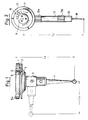
- a stylus is shown, which can be exchanged automatically, for example, via the changing device described in US Pat. No. 4,637,119, from a magazine constructed at the edge of the measuring range of the coordinate measuring machine in question.
- a change plate (1) is provided, on the top of which three cylinder bodies are arranged offset by 120 °. With these cylinder bodies, of which only one cylinder body, the cylinder body (9a) can be seen in the illustration according to FIG. 1, the changeable plate (1) reproducibly rests on a corresponding counter bearing on the underside of the probe on the coordinate measuring machine.
- the changeable plate (1) has a mounting cube (3) on its underside, on which up to five styli or stylus combinations can be screwed on all sides.
- a stylus (4) is attached to the underside of the mounting cube (3).
- the plate-shaped holder (1) is also provided with a circumferential groove (2).
- a fork-shaped carrier of the magazine (not shown) engages in this groove, in which the button is placed.
- a sensor (7) in the form of a platinum resistor is inserted in the plate-shaped holder (1).
- This sensor (7) is in good thermal contact with the stylus (4) and the other styli that can be attached to the mounting cube (3) due to the good thermal conductivity of the metallic material from which the parts (1,3,4) are made.
- the ends of the measuring resistor (7) are placed on contact pins (5) on the top of the adapter plate (1). In this way, the voltage drop across the measuring resistor is transmitted to corresponding counter contacts in the probe, and can be evaluated by a downstream measuring electronics.
- This measuring electronics thus determines the temperature of the inserted stylus combination after each probe change and reports this on to the control computer of the coordinate measuring machine.
- the linear expansion to be corrected is calculated from the determined difference to the temperature at which the stylus combination in question was calibrated, and taking into account the stylus lengths (LX or LZ) and the expansion coefficient of the stylus material. It is assumed here that the inserted stylus combination expands linearly in all axial directions and the angular position of the stylus combination is constantly reproduced by the changing process. It is therefore not necessary to recalibrate the button.
- the complete probe (14) with the resiliently mounted stylus (18) is attached via an extension piece (12) to the plate-shaped holder (11) which carries the exchange surface for an automatic exchange on the measuring arm of a coordinate measuring machine.
- the housing of the probe (14), the extension (12) and the change plate (11) as well as the union nuts (13a and 13b) connecting the parts are made of aluminum and are due to the good thermal conductivity of the material same temperature.
- a temperature sensor (17) is integrated in the changeable plate, which, however, is not visible in the view according to FIG. 2.
- the temperature sensor (17) is also a measuring resistor that is operated using four-wire technology.
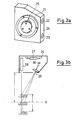
- an optical probe head that can be exchanged for the mechanical button from FIG. 2 is shown.
- This is a so-called triangulation button, the structure of which is outlined in a simplified manner in FIG. 3b. It has a laser diode (28), from which a measuring point is projected onto the object to be measured, and an optical system (29), which images the projected measuring point onto a row of diodes (30). The distance to the object is determined from the displacement of the measuring point on the diode row.
- buttons of this type the linear thermal linear expansion or the distance from the probe to the adapter plate (21) attached directly to the housing (24) of the button only plays a subordinate role.
- the mutual adjustment of the optoelectronic components to one another can change, among other things, due to the heat loss generated in the button itself, which results in errors in the distance measurement.
- a temperature sensor in the form of a measuring resistor (27) is housed in the housing (24), the connections of which are placed on four of the contacts (25) in the adapter plate (21).
- the temperature-dependent correction of the Length measurements of the button (24) take place here such that, for example, the drift of the zero point of the measurement range is measured for different temperatures and is stored in a memory table in the computer of the coordinate measuring machine.
- the voltage drop across the measuring resistor (27) and thus the current temperature of the triangulation button (24) is then queried at regular intervals and the distance measured values are corrected by the values stored in the table.
Landscapes
- Physics & Mathematics (AREA)
- General Physics & Mathematics (AREA)
- Length Measuring Devices With Unspecified Measuring Means (AREA)
- A Measuring Device Byusing Mechanical Method (AREA)
- Length Measuring Devices By Optical Means (AREA)
Applications Claiming Priority (2)
| Application Number | Priority Date | Filing Date | Title |
|---|---|---|---|
| DE8813875U | 1988-11-05 | ||
| DE8813875U DE8813875U1 (de) | 1988-11-05 | 1988-11-05 | Taster für Koordinatenmeßgeräte |
Publications (3)
| Publication Number | Publication Date |
|---|---|
| EP0368040A2 true EP0368040A2 (fr) | 1990-05-16 |
| EP0368040A3 EP0368040A3 (en) | 1990-11-07 |
| EP0368040B1 EP0368040B1 (fr) | 1993-02-10 |
Family
ID=6829584
Family Applications (1)
| Application Number | Title | Priority Date | Filing Date |
|---|---|---|---|
| EP89119244A Expired - Lifetime EP0368040B1 (fr) | 1988-11-05 | 1989-10-17 | Palpeur pour machine à mesurer les coordonnées |
Country Status (4)
| Country | Link |
|---|---|
| US (2) | US5014444A (fr) |
| EP (1) | EP0368040B1 (fr) |
| JP (1) | JPH0729450Y2 (fr) |
| DE (2) | DE8813875U1 (fr) |
Cited By (2)
| Publication number | Priority date | Publication date | Assignee | Title |
|---|---|---|---|---|
| EP0690286A1 (fr) * | 1994-06-30 | 1996-01-03 | Renishaw plc | Compensation de température pour une sonde tactile |
| US10444003B2 (en) | 2016-12-05 | 2019-10-15 | Quality Vision International, Inc. | Exchangeable lens module system for probes of interferometric optical measuring machines |
Families Citing this family (22)
| Publication number | Priority date | Publication date | Assignee | Title |
|---|---|---|---|---|
| US5276976A (en) * | 1992-09-15 | 1994-01-11 | Hawkes Hollis D | Indicator tip turret |
| DE4447905B4 (de) * | 1993-02-23 | 2005-04-28 | Faro Tech Inc | Koordinatenmessmaschine zum Messen von dreidimensionalen Koordinaten |
| US5410817A (en) * | 1993-05-18 | 1995-05-02 | Budd Co | Measuring tool with concentric point |
| US5341574A (en) * | 1993-06-29 | 1994-08-30 | The United States Of America As Represented By The Department Of Energy | Coordinate measuring machine test standard apparatus and method |
| GB9401692D0 (en) * | 1994-01-28 | 1994-03-23 | Renishaw Plc | Performing measurement or calibration on positioning machines |
| IT1279210B1 (it) * | 1995-05-16 | 1997-12-04 | Dea Spa | Dispositivo e metodo di visione per la misura tridimensionale senza contatto. |
| DE19915012A1 (de) * | 1999-04-01 | 2000-10-05 | Metronom Indvermessung Gmbh | Prüfkörper |
| US6941669B2 (en) * | 2000-06-30 | 2005-09-13 | Magus Gmbh | Method for determining effective coefficient of thermal expansion |
| DE10138138A1 (de) | 2001-08-09 | 2003-02-20 | Zeiss Carl | Korrektur des Temperaturfehlers bei einer Messung mit einem Koordinatenmessgerät |
| US7077643B2 (en) * | 2001-11-07 | 2006-07-18 | Battelle Memorial Institute | Microcombustors, microreformers, and methods for combusting and for reforming fluids |
| JP2004117161A (ja) * | 2002-09-26 | 2004-04-15 | Sharp Corp | 光学式変位センサ |
| JP4873613B2 (ja) * | 2002-10-07 | 2012-02-08 | アイノーラ テクノロジーズ インコーポレイテッド | 空間参照システム |
| EP2284486B1 (fr) * | 2004-12-16 | 2018-04-11 | Werth Messtechnik GmbH | Appareil de mesure de coordonnées et procédé de mesure à l'aide d'un appareil de mesure de coordonnées |
| US8141264B2 (en) * | 2007-05-31 | 2012-03-27 | Brunson Instrument Company | Length reference bar system and method |
| WO2009089219A1 (fr) * | 2008-01-07 | 2009-07-16 | Mark David Osterstock | Appareil de mesure de coordonnées |
| US8832953B2 (en) * | 2008-01-07 | 2014-09-16 | Q-Mark Manufacturing, Inc. | Coordinate measuring apparatus |
| DE102009060784A1 (de) * | 2009-12-22 | 2011-06-30 | Carl Zeiss 3D Automation GmbH, 73447 | Taststift und Tastkopf für ein Koordinatenmessgerät |
| IT1402715B1 (it) * | 2010-10-29 | 2013-09-18 | Marposs Spa | Sonda di tastaggio |
| CN102175146B (zh) * | 2010-12-31 | 2012-06-27 | 南京工业大学 | 基于具有触觉功能测量笔的自动三维视觉测量系统 |
| EP3259097B1 (fr) * | 2015-02-19 | 2024-11-06 | KUKA Systems GmbH | Installation de fabrication et procédé |
| WO2020178678A1 (fr) * | 2019-03-05 | 2020-09-10 | Medacta International Sa | Outil de préhension et de positionnement pour un guide d'insertion de vis polyaxiale vertébrale |
| JP2024129692A (ja) * | 2023-03-13 | 2024-09-27 | 株式会社東京精密 | 測定装置 |
Family Cites Families (17)
| Publication number | Priority date | Publication date | Assignee | Title |
|---|---|---|---|---|
| CH382451A (fr) * | 1961-09-30 | 1964-09-30 | Genevoise Instr Physique | Machine à mesurer ou machine-outil de précision |
| US3332153A (en) * | 1964-08-31 | 1967-07-25 | Bausch & Lomb | Temperature compensating system |
| DE2234146C2 (de) * | 1972-07-12 | 1984-03-29 | Hommelwerke GmbH, 7730 Villingen-Schwenningen | Elektrische Längenmeßeinrichtung |
| US3775655A (en) * | 1972-09-15 | 1973-11-27 | Xerox Corp | Method and apparatus for transducer temperature compensation |
| US3921300A (en) * | 1974-08-16 | 1975-11-25 | Us Navy | Temperature compensated measuring gauge |
| JPS54103367A (en) * | 1978-02-01 | 1979-08-14 | Olympus Optical Co Ltd | Thermal expansion correcting method of probe |
| DD152853A1 (de) * | 1980-09-01 | 1981-12-09 | Horst Donat | Wechseleinrichtung fuer messeinsatztraeger bei tastkoepfen |
| DE3348472C2 (de) * | 1983-06-03 | 1994-09-29 | Zeiss Carl Fa | Taststiftwechselhalter |
| DE3425476A1 (de) * | 1983-07-15 | 1985-01-24 | WERO oHG Röth & Co, 6490 Schlüchtern | Laengenmessvorrichtung nach dem zweistrahl-laser-interferometerprinzip |
| US4956606A (en) * | 1984-10-17 | 1990-09-11 | Mine Safety Appliances Company | Non-contact inductive distance measuring system with temperature compensation |
| GB8522984D0 (en) * | 1985-09-17 | 1985-10-23 | Renishaw Plc | Tool change apparatus |
| DE3620118C2 (de) * | 1986-06-14 | 1998-11-05 | Zeiss Carl Fa | Verfahren zur Bestimmung bzw. Korrektur des Temperaturfehlers bei Längenmessungen |
| DE3631825A1 (de) * | 1986-09-19 | 1988-03-31 | Zeiss Carl Fa | Verfahren zur reduzierung von temperatureinfluessen auf koordinatenmessgeraete |
| GB8624191D0 (en) * | 1986-10-08 | 1986-11-12 | Renishaw Plc | Datuming of analogue measurement probes |
| DE3706610A1 (de) * | 1987-02-28 | 1988-09-08 | Mauser Werke Oberndorf | Mess-signalverarbeitung fuer koordinatenmessmaschinen und bearbeitungsmaschinen |
| DE3715627A1 (de) * | 1987-05-11 | 1988-12-08 | Hommelwerke Gmbh | Vorrichtung zur messung des abstandes zwischen der vorrichtung und einer messflaeche |
| DE3729644C2 (de) * | 1987-09-04 | 1997-09-11 | Zeiss Carl Fa | Verfahren zur Bestimmung der Temperatur von Werkstücken in flexiblen Fertigungssystemen |
-
1988
- 1988-11-05 DE DE8813875U patent/DE8813875U1/de not_active Expired
-
1989
- 1989-10-17 DE DE8989119244T patent/DE58903523D1/de not_active Expired - Fee Related
- 1989-10-17 EP EP89119244A patent/EP0368040B1/fr not_active Expired - Lifetime
- 1989-11-03 US US07/431,570 patent/US5014444A/en not_active Expired - Lifetime
- 1989-11-06 JP JP1989129176U patent/JPH0729450Y2/ja not_active Expired - Fee Related
-
1991
- 1991-03-18 US US07/670,865 patent/US5065526A/en not_active Expired - Lifetime
Cited By (3)
| Publication number | Priority date | Publication date | Assignee | Title |
|---|---|---|---|---|
| EP0690286A1 (fr) * | 1994-06-30 | 1996-01-03 | Renishaw plc | Compensation de température pour une sonde tactile |
| US5675902A (en) * | 1994-06-30 | 1997-10-14 | Renishaw Plc | Probe head |
| US10444003B2 (en) | 2016-12-05 | 2019-10-15 | Quality Vision International, Inc. | Exchangeable lens module system for probes of interferometric optical measuring machines |
Also Published As
| Publication number | Publication date |
|---|---|
| EP0368040B1 (fr) | 1993-02-10 |
| JPH0729450Y2 (ja) | 1995-07-05 |
| US5065526A (en) | 1991-11-19 |
| DE8813875U1 (de) | 1988-12-22 |
| EP0368040A3 (en) | 1990-11-07 |
| US5014444A (en) | 1991-05-14 |
| DE58903523D1 (de) | 1993-03-25 |
| JPH0327305U (fr) | 1991-03-19 |
Similar Documents
| Publication | Publication Date | Title |
|---|---|---|
| EP0368040B1 (fr) | Palpeur pour machine à mesurer les coordonnées | |
| EP0364669B1 (fr) | Procédé de détection de la température d'objets de mesure sur instruments de mesure de coordonnées | |
| DE69207983T2 (de) | Kalibrier- und Messgerät | |
| DE60311527T2 (de) | Werkstückinspektionsverfahren und vorrichtung | |
| EP2343493B1 (fr) | Stylet et tête de palpage pour un appareil de mesure de coordonnées | |
| DE102015217637C5 (de) | Betreiben eines konfokalen Weißlichtsensors an einem Koordinatenmessgerät und Anordnung | |
| EP2759800B1 (fr) | Palpeur de mesure compensé en température | |
| EP1415124B1 (fr) | Correction d'une erreur due a la temperature pendant une mesure a l'aide d'un appareil de mesure de coordonnees | |
| EP2729763A1 (fr) | Correction et/ou prévention d'erreurs lors de la mesure de coordonnées d'une pièce | |
| DE3590550T1 (de) | Koordinatenmeßinstrument | |
| DE3714862A1 (de) | Flexible cnc-vielstellenmesseinrichtung | |
| EP3274655A1 (fr) | Calibrage d'un dispositif de rotation installé sur une partie mobile d'un appareil de mesure de coordonnées | |
| EP1110439A2 (fr) | Procede et dispositif pour etalonner un deplacement et/ou une position angulaire d'un systeme de retenue dans un dispositif destine a produire des blocs de composants electriques et substrat d'etalonnage | |
| DE3620118A1 (de) | Verfahren zur bestimmung bzw. korrektur des temperaturfehlers bei laengenmessungen | |
| DE10258579B4 (de) | Messeinrichtung | |
| DE102015109612A1 (de) | Koordinatenmessgerät und Verfahren zum Kalibrieren desselben mit einer Time-of-Flight-Kamera | |
| DE3933575C2 (fr) | ||
| DE102020114673B3 (de) | Sphärischer Parallelmanipulator, Schwenkeinrichtung und Messgerät | |
| DE102015205569A1 (de) | Kalibrierung eines beweglichen Teils eines Koordinatenmessgeräts oder eines daran angebrachten taktilen Tasters | |
| DE4227817C2 (de) | Mehrfach-Meßsystem für Oberflächen | |
| DE102015205566B4 (de) | Kalibrierung eines an einem beweglichen Teil eines Koordinatenmessgeräts angebrachten taktilen Tasters | |
| DE10128623B4 (de) | Verfahren zur Korrektur eines Messwerts einer Maschine zum Messen des Oberflächenaufbaus und Maschine zum Messen des Oberflächenaufbaus | |
| EP0644397A2 (fr) | Pied à coulisse linéaire électronique à grande portée | |
| EP4524512B1 (fr) | Artefact d'étalonnage | |
| EP1137973B1 (fr) | Procede et dispositif pour reduire les ecarts de mesure dues a la temperature, dans des systemes de mesure places en parallele |
Legal Events
| Date | Code | Title | Description |
|---|---|---|---|
| PUAI | Public reference made under article 153(3) epc to a published international application that has entered the european phase |
Free format text: ORIGINAL CODE: 0009012 |
|
| AK | Designated contracting states |
Kind code of ref document: A2 Designated state(s): CH DE FR GB IT LI NL |
|
| PUAL | Search report despatched |
Free format text: ORIGINAL CODE: 0009013 |
|
| AK | Designated contracting states |
Kind code of ref document: A3 Designated state(s): CH DE FR GB IT LI NL |
|
| 17P | Request for examination filed |
Effective date: 19901130 |
|
| 17Q | First examination report despatched |
Effective date: 19910724 |
|
| ITF | It: translation for a ep patent filed | ||
| GRAA | (expected) grant |
Free format text: ORIGINAL CODE: 0009210 |
|
| AK | Designated contracting states |
Kind code of ref document: B1 Designated state(s): CH DE FR GB IT LI NL |
|
| REF | Corresponds to: |
Ref document number: 58903523 Country of ref document: DE Date of ref document: 19930325 |
|
| GBT | Gb: translation of ep patent filed (gb section 77(6)(a)/1977) |
Effective date: 19930421 |
|
| ET | Fr: translation filed | ||
| PG25 | Lapsed in a contracting state [announced via postgrant information from national office to epo] |
Ref country code: CH Effective date: 19931031 Ref country code: LI Effective date: 19931031 |
|
| PLBE | No opposition filed within time limit |
Free format text: ORIGINAL CODE: 0009261 |
|
| STAA | Information on the status of an ep patent application or granted ep patent |
Free format text: STATUS: NO OPPOSITION FILED WITHIN TIME LIMIT |
|
| 26N | No opposition filed | ||
| PG25 | Lapsed in a contracting state [announced via postgrant information from national office to epo] |
Ref country code: NL Effective date: 19940501 |
|
| NLV4 | Nl: lapsed or anulled due to non-payment of the annual fee | ||
| PG25 | Lapsed in a contracting state [announced via postgrant information from national office to epo] |
Ref country code: FR Effective date: 19940630 |
|
| REG | Reference to a national code |
Ref country code: CH Ref legal event code: PL |
|
| REG | Reference to a national code |
Ref country code: FR Ref legal event code: ST |
|
| REG | Reference to a national code |
Ref country code: GB Ref legal event code: IF02 |
|
| RAP2 | Party data changed (patent owner data changed or rights of a patent transferred) |
Owner name: CARL-ZEISS-STIFTUNG TRADING AS CARL ZEISS Owner name: CARL ZEISS |
|
| REG | Reference to a national code |
Ref country code: GB Ref legal event code: 732E |
|
| PG25 | Lapsed in a contracting state [announced via postgrant information from national office to epo] |
Ref country code: IT Free format text: LAPSE BECAUSE OF NON-PAYMENT OF DUE FEES;WARNING: LAPSES OF ITALIAN PATENTS WITH EFFECTIVE DATE BEFORE 2007 MAY HAVE OCCURRED AT ANY TIME BEFORE 2007. THE CORRECT EFFECTIVE DATE MAY BE DIFFERENT FROM THE ONE RECORDED. Effective date: 20051017 |
|
| PGFP | Annual fee paid to national office [announced via postgrant information from national office to epo] |
Ref country code: GB Payment date: 20061023 Year of fee payment: 18 Ref country code: DE Payment date: 20061023 Year of fee payment: 18 |
|
| GBPC | Gb: european patent ceased through non-payment of renewal fee |
Effective date: 20071017 |
|
| PG25 | Lapsed in a contracting state [announced via postgrant information from national office to epo] |
Ref country code: DE Free format text: LAPSE BECAUSE OF NON-PAYMENT OF DUE FEES Effective date: 20080501 |
|
| PG25 | Lapsed in a contracting state [announced via postgrant information from national office to epo] |
Ref country code: GB Free format text: LAPSE BECAUSE OF NON-PAYMENT OF DUE FEES Effective date: 20071017 |