EP3259097B1 - Installation de fabrication et procédé - Google Patents
Installation de fabrication et procédé Download PDFInfo
- Publication number
- EP3259097B1 EP3259097B1 EP16708368.2A EP16708368A EP3259097B1 EP 3259097 B1 EP3259097 B1 EP 3259097B1 EP 16708368 A EP16708368 A EP 16708368A EP 3259097 B1 EP3259097 B1 EP 3259097B1
- Authority
- EP
- European Patent Office
- Prior art keywords
- production
- load
- workpiece
- receiving means
- type
- Prior art date
- Legal status (The legal status is an assumption and is not a legal conclusion. Google has not performed a legal analysis and makes no representation as to the accuracy of the status listed.)
- Active
Links
Images



Classifications
-
- B—PERFORMING OPERATIONS; TRANSPORTING
- B23—MACHINE TOOLS; METAL-WORKING NOT OTHERWISE PROVIDED FOR
- B23P—METAL-WORKING NOT OTHERWISE PROVIDED FOR; COMBINED OPERATIONS; UNIVERSAL MACHINE TOOLS
- B23P21/00—Machines for assembling a multiplicity of different parts to compose units, with or without preceding or subsequent working of such parts, e.g. with program control
- B23P21/004—Machines for assembling a multiplicity of different parts to compose units, with or without preceding or subsequent working of such parts, e.g. with program control the units passing two or more work-stations whilst being composed
-
- B—PERFORMING OPERATIONS; TRANSPORTING
- B23—MACHINE TOOLS; METAL-WORKING NOT OTHERWISE PROVIDED FOR
- B23P—METAL-WORKING NOT OTHERWISE PROVIDED FOR; COMBINED OPERATIONS; UNIVERSAL MACHINE TOOLS
- B23P23/00—Machines or arrangements of machines for performing specified combinations of different metal-working operations not covered by a single other subclass
- B23P23/06—Metal-working plant comprising a number of associated machines or apparatus
-
- B—PERFORMING OPERATIONS; TRANSPORTING
- B62—LAND VEHICLES FOR TRAVELLING OTHERWISE THAN ON RAILS
- B62D—MOTOR VEHICLES; TRAILERS
- B62D65/00—Designing, manufacturing, e.g. assembling, facilitating disassembly, or structurally modifying motor vehicles or trailers, not otherwise provided for
- B62D65/02—Joining sub-units or components to, or positioning sub-units or components with respect to, body shell or other sub-units or components
- B62D65/022—Transferring or handling sub-units or components, e.g. in work stations or between workstations and transportation systems
-
- G—PHYSICS
- G05—CONTROLLING; REGULATING
- G05B—CONTROL OR REGULATING SYSTEMS IN GENERAL; FUNCTIONAL ELEMENTS OF SUCH SYSTEMS; MONITORING OR TESTING ARRANGEMENTS FOR SUCH SYSTEMS OR ELEMENTS
- G05B19/00—Program-control systems
- G05B19/02—Program-control systems electric
- G05B19/418—Total factory control, i.e. centrally controlling a plurality of machines, e.g. direct or distributed numerical control [DNC], flexible manufacturing systems [FMS], integrated manufacturing systems [IMS] or computer integrated manufacturing [CIM]
- G05B19/41805—Total factory control, i.e. centrally controlling a plurality of machines, e.g. direct or distributed numerical control [DNC], flexible manufacturing systems [FMS], integrated manufacturing systems [IMS] or computer integrated manufacturing [CIM] characterised by assembly
-
- B—PERFORMING OPERATIONS; TRANSPORTING
- B23—MACHINE TOOLS; METAL-WORKING NOT OTHERWISE PROVIDED FOR
- B23P—METAL-WORKING NOT OTHERWISE PROVIDED FOR; COMBINED OPERATIONS; UNIVERSAL MACHINE TOOLS
- B23P2700/00—Indexing scheme relating to the articles being treated, e.g. manufactured, repaired, assembled, connected or other operations covered in the subgroups
- B23P2700/50—Other automobile vehicle parts, i.e. manufactured in assembly lines
-
- G—PHYSICS
- G05—CONTROLLING; REGULATING
- G05B—CONTROL OR REGULATING SYSTEMS IN GENERAL; FUNCTIONAL ELEMENTS OF SUCH SYSTEMS; MONITORING OR TESTING ARRANGEMENTS FOR SUCH SYSTEMS OR ELEMENTS
- G05B2219/00—Program-control systems
- G05B2219/30—Nc systems
- G05B2219/31—From computer integrated manufacturing till monitoring
- G05B2219/31036—Load component into corresponding compartment, bin, storage before assembly
-
- G—PHYSICS
- G05—CONTROLLING; REGULATING
- G05B—CONTROL OR REGULATING SYSTEMS IN GENERAL; FUNCTIONAL ELEMENTS OF SUCH SYSTEMS; MONITORING OR TESTING ARRANGEMENTS FOR SUCH SYSTEMS OR ELEMENTS
- G05B2219/00—Program-control systems
- G05B2219/30—Nc systems
- G05B2219/50—Machine tool, machine tool null till machine tool work handling
- G05B2219/50393—Floor conveyor, AGV automatic guided vehicle
-
- Y—GENERAL TAGGING OF NEW TECHNOLOGICAL DEVELOPMENTS; GENERAL TAGGING OF CROSS-SECTIONAL TECHNOLOGIES SPANNING OVER SEVERAL SECTIONS OF THE IPC; TECHNICAL SUBJECTS COVERED BY FORMER USPC CROSS-REFERENCE ART COLLECTIONS [XRACs] AND DIGESTS
- Y02—TECHNOLOGIES OR APPLICATIONS FOR MITIGATION OR ADAPTATION AGAINST CLIMATE CHANGE
- Y02P—CLIMATE CHANGE MITIGATION TECHNOLOGIES IN THE PRODUCTION OR PROCESSING OF GOODS
- Y02P90/00—Enabling technologies with a potential contribution to greenhouse gas [GHG] emissions mitigation
- Y02P90/02—Total factory control, e.g. smart factories, flexible manufacturing systems [FMS] or integrated manufacturing systems [IMS]
Definitions
- the invention relates to a production plant and a method having the features of the preambles of the method and device main claims.
- Such a method and such a device are disclosed, in particular a production plant designed as a robot garden for the bodyshell of vehicle bodies is known, in which supplied workpieces or body parts of different types are each picked up by a robot-guided, type-specific gripping device and remain permanently connected to this as a unit during workpiece processing by welding robots and during transport.
- Handling robots handle and transport the unit in a robot cell and pass it on to the next robot cell via storage tables.
- the gripping devices each have their own network with a code transmitter for identifying the respective gripping device.
- the FR 2 757 819 A2 shows a production plant for the bodyshell construction of different types of vehicle bodies, in which the type-specific workpieces are picked up on type-specific pallets with a type identification and transported one after the other on a ring-shaped conveyor through several, firmly linked production zones. The processing or welding of the workpieces takes place on the same pallet that already contains the required workpieces.
- the US 4 894 908 A deals with an assembly system for couplings in which pallets of the same type circulate and are loaded by robots with externally supplied coupling parts.
- production systems for the bodyshell of vehicle bodies are also known in which the production area is divided into two or more separate lines in which production cells are firmly linked together by conveyor technology.
- the sequence of production steps and the production cells involved is fixed.
- the workpiece transport from cell to cell is usually carried out by handling robots.
- the automated manufacturing technology used i.e. the production plant and the manufacturing process, are characterized by a high degree of flexibility.
- the one or more production devices arranged in the production plant can independently carry out a processing process based on a locally recorded type identification of a load-carrying device. Depending on the type of the load-handling device to carry out different machining processes. Different application-specific tools can also be used for this.
- the production facilities and the machining processes carried out there can also be quickly converted if required.
- the different type identifiers correlate with the different workpieces.
- the assignment is freely selectable and can be changed.
- the control system also recognizes the respective workpiece based on the type of load-handling device recorded.
- the load-handling device can be used to position the workpiece precisely and in a way that is suitable for processing.
- At least two different types of load-handling devices can be used within a production plant. Preferably, a large number of different types are used. Within a larger production plant, the same types can be used in different and spatially and functionally separate plant areas.
- a type identifier can be designed as a code and contain additional information and data in addition to the type information.
- additional information and data can include an identity specification of the load-handling device and/or a workpiece or model specification and/or an identifier of the last production facility or production cell visited.
- the production facilities can be used to process and handle multi-part workpieces or assemblies. This includes lifting and releasing a workpiece from the load-handling device for further processing in a suspended position and can include assembling workpiece parts.
- the workpiece processing can also take place on the load-handling device, which can be positioned in a suitable manner together with the workpiece in a predetermined position.
- the load-handling device can remain connected to the conveyor or be separated from it.
- a workpiece is reloaded from one load-handling device to another load-handling device of the same or different type.
- an automatic manufacturing device for workpieces in particular for bodywork components, is provided in the production plant, which has at least one program-controlled manufacturing means and a processing area, wherein a manufacturing means is arranged in a processing area designed for the sequential reception of at least two load-handling means of different types, which is designed for handling a workpiece, for holding the workpiece in suspension during the processing process, and for transferring the workpiece to another load-handling means of the same or a different type (A, B, C, D).
- the invention relates to a method for machining workpieces, in particular body components, in an automatic production facility which has at least one program-controlled production means and a processing area, with the following method steps: Picking up the workpiece by at least one production means from a first load-carrying device, Moving the first load-handling device out of the processing area of the first production facility, moving a second load-handling device, which is different from the first load-handling device, into the processing area of the first production facility and placing the workpiece on the second load-handling device.
- the method also includes the aforementioned floating holding of the workpiece during the processing process and the reloading of the workpiece onto another load-handling device of the same or a different type (A, B, C, D).
- the reloading can be done directly or via an intermediate storage area in the processing area. Workpiece processing can also take place here.
- the connecting conveyor technology can be relocated to the production facility and simplified and the effort required reduced.
- the load-handling devices can be changed during the production process, whereby another workpiece that has already been processed or new workpiece parts can be fed in together with the second or further load-handling device.
- the load-handling devices or the conveyor device can be decoupled from the processing process at least temporarily and used more efficiently.
- the transfer of workpieces between identical or different load-handling devices in a production facility, in particular in a processing area there and with the production device(s) available there, has the aforementioned independent inventive significance. This can also be used without a type identification and its recording.
- the manufacturing facility can be designed for a primary process and can be connected to another manufacturing facility for a secondary process on a workpiece.
- the further Production equipment serves as an extended workbench. Processes can be carried out here, for example, that are not possible or only possible with difficulty in the application-flexible production equipment.
- Several other production equipment can be connected to the primary production equipment in a quadrant matrix.
- cycle time can be saved and production performance increased by diversification and simultaneous execution of several processes.
- the workpiece can be changed via interfaces on the edge of the production equipment.
- the interfaces can be located on a protective partition surrounding the respective production equipment.
- the interfaces on the conveyor path can be designed as locks for empty and loaded conveyors in the protective partition.
- the manufacturing technology used allows for decentralized control of a production plant and a reduction and flexibility of the control effort.
- conversions of the production plant and a production process as well as the integration of additional workpieces, machining processes and production processes can be carried out quickly and with little effort.
- the previously usual overall plant control system covering all processes can be omitted.
- the production facilities are themselves highly flexible and can be used for a wide variety of workpieces and applications, e.g. joining processes, in particular welding, soldering or Bonding processes, forming processes, assembly processes, application processes or similar.
- the application-specific tools required for this can be kept in an external supply and, if required, transported to the Production facilities for their automatic tooling and conversion.
- the same conveyor system can also be used to transport the workpieces.
- the automated production plant has a flexible and, if required, reconfigurable conveyor-based linking of the production facilities on the one hand with each other and on the other hand with provisions, in particular for various application-specific tools and for different workpieces.
- the highly flexible conveyor system can be designed in any suitable manner. It preferably comprises a large number of autonomous and individually controllable conveyors that move on a large number of different conveyor paths.
- a network of conveyor paths is preferably present on which the conveyors travel on predetermined conveyor tracks between the production facilities and the provision areas, whereby the conveyor tracks can be freely selected and programmed.
- the conveyor system is also flexible in terms of the transport options for application-specific tools and for workpieces.
- Adapted load-handling devices are provided for this purpose, which are permanently or interchangeably connected to the conveyors.
- the conveyors and/or the load-handling devices can also be stored in one or more provision areas and retrieved and used as required.
- the processing of a single or multi-part workpiece can be carried out in a production process and a sequence of several production steps or production segments, whereby the production steps are each controlled autonomously in the production facilities of a production plant by the respectively selected control program and the production process is controlled by a warehouse manager of the production facility via the relocation of the load handling equipment or the conveyor system.
- the plurality of control programs is stored in a storage means of the control device, in particular in exactly one storage means.
- the plurality of control programs comprises at least one control program for at least two types of load-handling means.
- the storage means contains at least two control programs, namely at least one control program for each of the at least two types of load-handling means.
- a first control program can be provided to control the at least one manufacturing means for processing or handling a first type of load-handling means and a second control program is provided to control the at least one manufacturing means for processing or handling a second type of load-handling means.
- the storage means can also have two or more control programs for processing or handling or handling a single type of load-handling means.
- the storage means can have at least one control program for all types of load-handling means.
- a parking area for load-handling devices is assigned to and connected upstream of at least one production facility.
- the parking area can be used as a buffer and also for sequence healing if several different types of load-handling devices are to control the production facility in a predetermined sequence and arrive in the wrong order. This is particularly the case when a workpiece is being reloaded from one processing area to another. Load handling equipment is advantageous.
- the various types of load-handling devices are each transported in their own production loop on a programmed, preferably ring-shaped conveyor track.
- the production loop can extend over one or more assigned production facilities and, if necessary, over a provision for workpieces and/or tools and/or LAM.
- the production loop can, for example, correspond to a production process for a workpiece and the production steps provided for this to produce a finished or intermediate product. Loop formation simplifies the conveyor and programming effort and shortens the conveyor distances.
- One or more conveyors can run on a production loop.
- a buffer storage for loaded load-handling devices can be assigned to a provision for workpieces and, if necessary, integrated into a production loop. The processing and loading times can be decoupled and the number of conveyors for transporting the load-handling devices can be reduced.
- the invention relates to a manufacturing plant (1) and a manufacturing method for workpieces (2,2').
- the invention further relates to a manufacturing device (18-22) for workpieces (2,2') and manufacturing processes taking place there.
- the production plant (1) and its components, in particular the production equipment (18-22), are automated and program-controlled.
- the workpieces (2, 2') can be of any type and size. They can be one-piece or multi-piece. They are preferably body components of vehicle bodies.
- the production system (1) can be used, for example, for the body shell of vehicle bodies.
- the workpieces (2) and (2') are designed differently.
- Figures 8 to 10 one or more workpieces (2,2') are processed in a sequence of production steps (44-47) with different production processes.
- the number of steps depends on the process volume, the utilization, cycle times and other criteria.
- a production product (43) in particular a body assembly, is produced by assembling and joining workpiece parts. This can be an intermediate product from which a final product is produced with further processes, e.g. connection with other workpiece parts or other intermediate products.
- the production steps (44-47) are preferably carried out in a sequence one after the other in several production facilities (18-22). In this case, according to Figure 8 and 9 In each production step (44-47) one or more process segments are carried out.
- These manufacturing processes can involve different techniques, e.g. joining, in particular welding, soldering or gluing, applying and removing materials, heat treatments, forming, machining, assembly and installation processes or the like.
- the production plant (1), the production process and the production equipment (18-22) are flexible and can be adapted to suit the specific application.
- An application specification refers to an adaptation to different production processes and/or to different workpieces (2,2').
- the application-specific tools (8) can be individual tools or set tools. They can be Figure 8 consist of several tool segments (41).
- tools (8) are referred to below as tools (8).
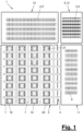
- FIG 1 shows a schematic representation of a production plant (1) and its components.
- the production plant (1) has a production area (3) with several production facilities (18-22) arranged therein.
- the production plant (1) also has a supply (10) for workpieces (2,2') and a supply (11) for various said tools (8).
- a conveyor device (4) is present which flexibly connects the production facilities (18-22) to one another and to the preferably external supplies (10,11).
- the supplies (10,11) are also referred to as warehouse (10) and tool store (11).
- the conveyor device (4) can be designed in any suitable manner. In the embodiments shown, it has a plurality of autonomous and individually controllable conveyor means (5) as well as a plurality of conveyor paths (7) on which the conveyor means (5) travel.
- the conveyor paths (7) are preferably arranged in a network and cross each other several times.
- a conveyor path (7) can extend through a production facility (18-22). Several continuous conveyor paths (7) can be connected to one another and together form a conveyor line (70).
- the conveyors (5) are preferably autonomous and individually controllable and, if necessary, steerable. They are designed, for example, as floor-bound driverless transport vehicles, so-called AGV or FTF. They can negotiate curves or, if necessary, turn on the spot. They can also move omnidirectionally, e.g. using Mecanum wheels. Alternatively, the conveyors (5) can be arranged hanging and, for example, travel on elevated conveyor rails with switches. They can also be designed as roller or belt conveyors.
- the conveyor device (4) can have several different conveyors (5).
- the conveyors (5) travel in the network of conveyor paths (7) and conveyor lines (70,71) on freely programmable conveyor tracks.
- the conveyor lines (70,71) can be traveled in opposite directions. They can also be designed as one-way streets with opposite directions of travel indicated by arrows.
- the cross connections, in particular the access corridor(s) (66), can be used to form conveyor loops (48,49), which also create production loops by linking several production facilities (18-22).
- the production or conveyor loops (48,49) can overlap one another.
- the conveyors (5) can optionally continue along the conveyor path (7) or the conveyor line (70) from one production facility (18-22) to the other or turn on the cross connection and travel to another conveyor line (71).
- the turning can be carried out by a steering movement of the conveyor (5), by moving it using a turntable or in another way.
- a parking area (53) for temporarily parking an empty or loaded conveyor (5) can be created in the access corridor (66) or the cross connection. This allows buffer storage to be created for compensating for cycle time differences or disruption phases or for sequence healing or other purposes.
- the conveying means (5) preferably each have their own individually controllable drive and their own programmable control.
- the energy supply can be provided in any suitable manner, e.g. by a stationary or non-stationary energy supply device (33).
- the conveyors (5) each carry one or more adapted load-handling devices (6). These are abbreviated to LAM below.
- the LAM (6) can be arranged fixedly or interchangeably on a conveyor (5).
- the LAM (6) can have a fixed adaptation for certain workpieces (2,2') and/or tools (8). Alternatively, they can be designed to be flexible or adjustable and adaptable in different ways.
- the LAM (6) can have different adapted holders and holding means for the workpieces (2,2') and/or tools (8) and hold them in a defined position.
- the LAM (6) can have a plate- or frame-shaped carrier as a base, for example.
- LAMs (6) are designed in different ways and form different types (A, B, C, D). They can be adapted to different workpieces (2, 2').
- An adjustable LAM (6) can form two or more different types.
- the number of different LAM types (A, B, C, D) can be as high as desired. It is two, three, four or more. The number can depend on the process volume to be produced in the production plant (1), in particular on the number of different workpieces (2, 2'). Additional LAM types can be available for the tools (8).
- the different types of LAM (6) have a type identifier (37) for their respective type (A, B, C, D). This can be fixed or changeable.
- An adjustable LAM (6) can also have an adjustable type identifier (37).
- the type identifier (37) can be linked to a specific workpiece (2, 2') in terms of information and control technology. It can represent the type of workpiece (2,2') and/or tool (8).
- the type identifier (37) is independent of the state of the workpiece (2,2') and/or tool (8) on the LAM (6). In a production sequence over several production steps (44-47), the type identifier (37) therefore does not change.
- the type identifier (37) can, however, be changed for other reasons, e.g. in the case of a technical conversion of the LAM (6).
- the type identifier (37) can be designed in different ways. It can, for example, consist of a code attached to the LAM (6), which can be designed in any way, eg mechanical, magnetic, electrical, inductive, in particular as an RFID chip. A code can contain further information, eg an identification number of the LAM (6). A type identifier (37) can alternatively or additionally be formed by a color or shape feature of the LAM (6). Figure 3 shows this arrangement.
- the production plant (1) has a supply (9) for the various LAMs (6) connected to the conveyor (4).
- the supplies (9,10,11) can be of the same type.
- Such a supply (9,10,11) can have, for example, a storage area (32) for workpieces (2,2') and/or tools (8) and/or LAMs (6) and a loading area (30) connected to the conveyor (4) with a loading device (31).
- the loading device (31) comprises, for example, one or more loading robots that are arranged stationary or are arranged so as to be movable by means of a travel axis along a single or a row of conveyors (5) with LAMs (6).
- the Conveyor device (4) is designed to move at least one type, in particular all types (A, B, C, D), of load-carrying means (6) to and from the production device(s) (18-22).
- the production devices (18-22) are surrounded on several sides by conveyor paths (7).
- a conveyor path (7) extends in and preferably through a production device (18-22).
- the conveyor means (5) with the LAM (6) can therefore travel in and preferably through the individual production devices (18-22).
- the production devices (18-22) are preferably distributed in a uniform, in particular Cartesian, matrix.
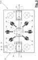
- At least several production facilities (18-22) are designed identically to one another. Preferably, they are designed as individual production cells (23). Alternatively, another design, e.g. multi-cell design, is possible. In Figure 3 a cell-like manufacturing facility (18-22) is shown as an example.
- the processing area (26) serves for the sequential recording of at least two different types of LAM (6) and the workpiece (2, 2') and/or tool (8) carried along in each case.
- the processing area (26) is located on a conveyor path (7) that extends into or through the production facility (18-22) (dead end or drive-through lane). This preferably straight
- the conveyor path (7) can only be used in one or preferably in both directions.
- the production device (18-22) has a Figure 3 schematically indicated positioning device (58) for process-appropriate positioning of the LAM (6) and/or the conveyor (5). This also enables exact positioning of one or more workpieces (2) and/or one or more tools (8) carried along.
- the positioning device (58) can act mechanically on the LAM (6) and/or the conveyor (5).
- a positioning device (58) can be formed by tactile or contactless detectable markings in the area of the conveyor path (7), which are detected by the conveyor (5) and ensure its program-controlled and self-driven positioning.
- stops that can be pivoted into the travel path for the longitudinal and lateral positioning of the LAM (6) and/or conveyor (5) can be present.
- a positioning device (58) can also be formed in terms of control technology via the programmed control of the conveyor (5) and its integrated path measurement or navigation.
- the production means (28, 29) can be designed the same or differently and can be present individually or in multiples. At least one production means (29) is used to machine a workpiece (2, 2') in the machining area (26), in particular on the LAM (6). The production means (29) can also additionally handle a workpiece (2, 2'). Preferably, another additional production means (28) is used to handle a workpiece (2, 2').
- the production means (28, 29) are, for example, distributed around the processing area (26). In particular, they are located on both sides of the processing area (26) and the conveyor path (7).
- the production means (28, 29) can be arranged stationary or movable by means of an additional axis.
- the application-flexible production means (28, 29) are preferably designed as multi-axis and programmable industrial robots. They have an automatic change coupling on their output elements, in particular their hand flanges. This means they can automatically pick up the required tool (8) or tool segment (41), use it and, if necessary, automatically release and change it.
- a production means (29) can be designed in another way, e.g. as a machine tool.
- the application-flexible production means (28, 29) are preferably provided for different tasks.
- the production means (29) have, for example, interchangeable application-specific tools (8) for carrying out the respective production process, which are designed, for example, as joining tools, forming tools or the like. These production means (29) are designed, for example, as welding robots.
- the other production means (28) also carry interchangeable application-specific tools (8), which are designed, for example, for handling the one or more workpieces (2) during the production process. These tools (8) can be gripping tools.
- the production means (28) are designed, for example, as handling robots.
- workpiece parts can be moved and assembled, for example. Furthermore, the workpiece (2,2') can be detached from the LAM (6). It is lifted off and held in a suspended position, whereby processing can be continued if necessary.
- the LAM separated from the workpiece (2,2') (6) can be moved during further processing and transported away from the production facility (18-22). Furthermore, the released workpiece (2,2') is placed and reloaded onto a second LAM (6) transported into the processing area (26).
- the second LAM (6) can be of the same type or of a different type. Another workpiece can also be fed onto the second LAM (6).
- the production facility (18-22), in particular the production cell (23), has one or more storage units (27) for the said tools (8).
- the storage units (27) can have several storage locations for different tools (8). They can be driven and controllable. They can be designed as rotary storage units, for example.
- the storage units (27) are each located in the working area of a production tool (28, 29). In the embodiment shown, four storage units (27) are arranged in the corner areas, each of which is assigned to a production tool (28) or handling robot.
- control device (38) with a storage means (39) for a plurality of application-specific control programs (40) adapted to different LAM types (A, B, C, D). Control programs are present and stored for at least two types (A, B), preferably for all types (A, B, C, D) of the LAM (6).
- the control device (38) is neutral in itself and becomes a process manager by assigning application-specific process segments explained below.
- the production device (18-22) also has a detection device (36) for the type identification (37).
- the detection device (36) can be part of the control device (38).
- the detection device (36) can be arranged inside the production facility (18-22), preferably at the entrance area. Alternatively, it can be arranged outside and, for example, on a conveyor path (7).
- the control device (38) determines the type (A, B, C, D) of the LAM (6) located in the processing area (26) based on the type identifier (37) detected by the detection device (36).
- the detection device (36) can have an optical sensor, an electromagnetic sensor, a tactile sensor, an electrical sensor and/or a magnetic sensor.
- a sensor can be designed in particular as an antenna, as a near field communication, as a capacitive or inductive sensor.
- the production facility (18-22) and its production resources (28,29) as well as any other facility components have an application-neutral basic design and are adapted to the respective application by equipping them with application-specific tools (8) and by reprogramming or using a control program (40).
- This basic design and the possibility of equipping and adapting them make them application-flexible.
- the control device (38) selects a control program (40) from the stored program variety based on the detected and determined LAM type (A, B, C, D) and executes it.
- the control device (38) is connected to the at least one production means (28, 29) and controls it.
- a specific workpiece (2, 2') is assigned to the type identifier (37) or the LAM type.
- the selected control program (40) is adapted to the machining of this workpiece (2, 2').
- the production facility (18-22), in particular the production cell (23), can also have one or more supply facilities for operating resources, in particular electrical power, fluid media or the like, as well as auxiliary devices.
- a surrounding protective partition (24), e.g. in the form of a fence, can be present.
- the protective partition (24) there can be one or more locks (25) for the secure inlet and outlet of a conveyor (5) with LAM (6) on the conveyor path (7).
- one or more application-flexible production devices (18-22) can be connected to a further production device (67) for a secondary process on a workpiece (2.2").
- a multiple arrangement of such production devices (67) is also possible. These can be arranged laterally next to or above or below a production device (18-22).
- one or more program-controlled production means in particular industrial robots, for handling and processing the workpieces (2.2") as well as other devices, e.g. stationary welding guns, bolt setting devices, adhesive application devices, etc., can be arranged.
- the primary process(es) carried out in an application-specific production station (18-22) are preferably geometry-specific for the mentioned production product.
- Such processes can consist, for example, of assembling and joining.
- a joining process can consist of gluing (so-called pre-process) or geometry-determining spot welding or laser welding or riveting or clinching or the like.
- the one or more secondary processes in a further production facility (67) can be geometry-unspecific. They can, for example, consist of joining, measuring, shaping Processing, cutting or similar. When joining, additional parts such as bolts or similar can also be attached.
- Hard-coded secondary processes are also possible, which consist of punching, folding, drilling and/or milling or similar.
- the workpiece change between the application-specific production device (18-22) or the one or more further production devices (67) can take place via an interface (68) which is arranged, for example, at a passage of a protective partition (24).
- the further production areas (67) can also be surrounded by a protective partition (24).
- the workpiece change can be carried out by a program-controlled production means (28), in particular a handling robot.
- Further interfaces (69) can be arranged at the inlet and at the preferably opposite outlet of the production device (18-22) and can be formed, for example, by the locks (25).
- the production plant (1) has a controller (13) which is connected to control units (14-17) for the production devices (18-22), the conveyor device (4) and the provisions (9,10,11).
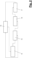
- Figure 2 shows an example of such a control architecture.
- the central system control (13) is connected to a control unit (14), a so-called warehouse manager, for the warehouse (10) and the production facility (18-22) and, if necessary, also the conveyor system (4).
- the warehouse manager (14) controls the location and relocation of the LAM (6) in the production facility (1). In particular, it gives the conveyor system (4) orders to transport the respective LAM (6) to the correct address, e.g. production facility or supply. It also controls the routing, ie the sequence of the LAMs (6) approached by Production facilities (18-22). The latter do not have to follow one another directly, but can be located anywhere in the production facility. During routing or the conveyor track being followed, production facilities (18-22) can be driven through or bypassed.
- the warehouse manager (14) includes a warehouse management system for controlling logistics processes from goods receipt to goods issue, for inventory management and inventory, for task management, for a transaction history, for warehouse configuration adjustment by administrators and for interfaces to system components of the production plant (1).
- the warehouse manager (14) also includes a material flow system with global control of the automated plant components, in particular the conveyor system (4), for transport management, for congestion and flow control, for the aforementioned routing and throughput optimization, for integrated troubleshooting across all levels, for coordination with subsystems, for plant individualization and for global material flow optimization.
- the tool store manager deals with the tool store (11). It includes a tool manager for logistics processes from tool receipt to tool issue, for picking tools for planned production, for managing storage locations and locations, for controlling and documenting maintenance intervals and for a history of all tools. The spare parts are also controlled with regard to inventory management and stocktaking.
- the tool store manager (15) is connected to a control unit (16), the so-called fleet manager. This contains interfaces to the logistics and material flow system and affects the functions of scheduling, planning and fleet management of the conveyors (5).
- the warehouse manager (14) also has a connection to the fleet manager (16).
- the fleet manager (16) carries out orders from both the warehouse manager (14) and the tool store manager (15).
- the fleet manager (16) is connected to another control unit (17), which is called the field manager. This deals with status control for processes in the production plant (1), interfaces to hall and building technology, and interfaces to quality assurance.
- the field manager (17) is in turn connected to the control unit (13).
- control devices (38) of the production facilities (18-22) and their control programs or process managers (4) are also connected to the system control (13), in particular the warehouse manager (14) and the tool store manager (15).
- the aforementioned connections between the controller (13) and the control units (14-17,40) are designed as signal lines. They can be wired or wireless.
- the tool store manager (15) controls the hardware and/or software equipment of the individual production facilities (18-22) or production resources (28,29). This concerns, for example, the loading of the production resources (28,29) or storage (27) with tools. (8) and the removal of tools (8) that are no longer required by means of LAM (6).
- the tool store manager (15) can also control the storage of the control programs (40) in the storage means (39) of the respective control devices (38). In particular, it can store the control programs (40) centrally and send them to the storage means (39).
- Figure 10 illustrates this schematically.
- the tool store manager (15) can plan and manage the process segments to be carried out on site during the production process in the production facilities (18-22).
- the latter each consist of the required tool (8) or tool segment (41) and the associated program sequences or tool segments (42) in the control program (40).
- the type-dependent call and execution of the control program (40) are carried out by the respective control device (38).
- the use and possible replacement of the tool (8) or the tool segments (41) can also be controlled by the control program (40).
- the processing of a single or multi-part workpiece (2,2') in a production process and a sequence of several production steps or production segments (44-47) is controlled autonomously in the production facilities (18-22) by the control program (40) selected in each case.
- the production process or the step sequence of the process segments and their addresses in the production facility (1) are managed by the warehouse manager (14) and controlled by the relocation of the load-handling devices (6) or the conveyor device (4).
- the control of the production facility (1) is thus decentralized.
- the control devices (38) or their process managers (40) report the start and end of a production process or process segment to the warehouse manager (14).
- the warehouse manager (14) then controls the conveyor device (4) accordingly for the further transport of the respective LAM (6) to the respective subsequent production device (19-22) in the production process or to a supply device (9,10,11,12) and for the feeding of the next LAM (6) to the work area (26).
- the production plant (1) with the production area (3) and the provision (9-12) as well as the conveyor (4) can be configured as desired.
- Various workpieces (2,2') can be manufactured in parallel. This can be, for example, the parallel production of left and right side walls, a body roof, a floor assembly or the like. The same applies to other types of workpieces (2,2') that are not designed as body components.
- various types of similar workpieces (2,2') can be manufactured in a free mix.
- the production facilities (18-22) can all carry out different production processes and production steps. For example, there can be a separate production facility (18-22) for each workpiece-related production step (44-47).
- the same or similar production processes or production steps can also be carried out on several different workpieces (2,2') in one production facility (18-22). It is also possible to carry out a production step for a specific workpiece (2,2') in parallel in two or more functionally identical production facilities (18-22). This can be useful, for example, to compensate for different cycle times for different production steps. It is also possible to reduce or increase production capacities and the number of production facilities (18-22) involved.
- the rapid, application-specific adaptation of the production system (1) and in particular of the production equipment (18-22) allows the individual application-related production jobs of the production equipment (18-22) to be changed flexibly and quickly.
- the tool conversion and reprogramming required for this and the resulting application-specific adaptation of the production equipment (18-22) can also be carried out very quickly.
- the conveyor system (4) with its conveyor tracks can also be changed and reprogrammed just as quickly.
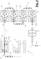
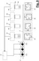
- Figure 4 illustrates an exemplary configuration of a production plant (1) with a production area (3) in which four production devices (18-21) are arranged in a row and are successively passed through by a conveyor path (7).
- the production devices (18-21) can be arranged accordingly Figure 3
- the conveyor (5) with the LAM (6) and the finished workpiece (2) can travel to a delivery area (34) where the workpiece (2) can be unloaded by robots or the like and removed from this part of the production facility (1). It can be taken to an intermediate storage facility, for example, or fed directly to another production area (3).
- Figure 4 also illustrates the warehouse (10) upstream of the production area (3), in which the conveyors (5) with LAM (6) are loaded with one or more workpieces (2,2') and then enter the production area (3).
- a provision (9) for LAM (6) and a provision (12) for conveyors (5) are upstream and connected to the warehouse (10) and the production area (3) via a conveyor path (7). connected.
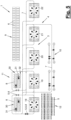
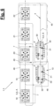
- Figure 5 and 6 show, by way of example, another configuration of the production plant (1) with a production area (3) having a row of five production devices (18-22).
- Figure 5 illustrates the application-specific preparation and equipment of the production area (3).
- the conveyors (5) from a supply (12) are first loaded with suitable LAMs (6) and then travel to a tool store (11), which can have one or more loading areas (30).
- the required application-specific tools (8) are loaded onto the conveyors (5) and LAMs (6), which then travel on programmed conveyor tracks to the respective production facilities (18-22) and there transfer the tools (8) to the production equipment (28,29) and, if necessary, the storage (27).
- reprogramming takes place in the control unit of the respective production facility (18-22).
- the setup can take place in parallel operation.
- the unloading of the tools (8) can be carried out in the production facilities (18, 22) by the production means (28, 29) there, whereby the tools (8) that are no longer required are alternately transferred to the conveyor (5) and the LAM (6).
- a handling device can be arranged for tool loading on the conveyor (5) and/or the LAM (6), which carries out the tool change and the reloading with tools (8).
- This handling device can be, for example, a multi-axis handling robot. This allows tools (8) and/or other devices to be placed outside the conveyor or passage path (7).
- Figure 6 illustrates this stage.
- the respective programmed conveyor paths of the conveyors (5) change.
- the reference number 7 designates the said programmed conveyor tracks on the existing conveyor paths.
- a warehouse (10) is connected to the production area (3) via the conveyor system (4), which can also have two or more loading areas (30).
- different workpieces (2,2') can be transported to the different production facilities (18-22).
- the production facilities (18-22) can again be loaded according to Figure 3 be trained.
- a conveyor (5) with LAM (6) of type D and a workpiece (2) designed, for example, as a set of parts moves from a loading area (30) into the first production facility (18).
- a process segment is carried out in a first production step (44), e.g. assembling and joining workpiece parts.
- the production means (28) or handling robots remove the workpiece parts from the LAM (6) using suitable tools (8), in particular geogrippers.
- the production means (28) can cooperate with one another and, if necessary, lock one another with their geogrippers and present the gripped and clamped workpiece parts to one or more production means (29), in particular welding robots, for joining. If necessary locked geogrippers are brought into further working positions in a group.
- one or more additional workpiece parts can be reloaded from one or more production means (28) by the LAM (6) and added to the workpiece parts already gripped.
- the produced workpiece is placed back on the conveyor (5) and/or the LAM (6) and then transported away from the production facility (18).
- laser welding takes place on the gripped workpiece parts using a remote laser, with the partially joined workpiece (2) having a state 1 at the end of the production step (44).
- the workpiece (2) After the second manufacturing step (45) in the following manufacturing facility (19) and the individual process segment there with another attached workpiece part, the workpiece (2) has a state 2. After the third manufacturing facility (20) and the third manufacturing step (46) with one process segment, the workpiece (2) has a state 3. In the fourth manufacturing facility (21) and in the fourth manufacturing step (46) with two process segments, the workpiece (2) or the finished product (43) is completed in the form of an assembly with the state 4 and transported away.
- a second workpiece (2') on a LAM (6) of type C can be Figure 8 and 9 are also moved through the production facilities (18-22).
- a machining process with two process segments only takes place in the first production facility (18).
- No machining takes place in the second, third and fourth production facilities (19,20,21).
- the further production process may extend to other production facilities.
- the workpieces (2,2') are processed and transported in parallel and independently of one another.
- Production stations (18-22) without intended processing of the respective workpiece (2,2') can be passed through or bypassed.
- the workpiece (2) can be lifted off the LAM (6) in its entirety, whereby the conveyor (5) with the empty LAM (6) of type A leaves the manufacturing facility and a new conveyor (5) with a LAM (6) of a different type B enters, whereby the finished workpiece (2) is then deposited and transported further.
- the produced workpiece (2) can be loosely supplemented or joined with another workpiece (2') or workpiece parts, possibly manufactured in a different way, which are fed onto the other LAM (6) of type B.
- This LAM (6) is adapted to accommodate both workpieces (2,2') or workpiece parts.
- the produced workpiece (2) can be placed on the LAM (6) in the correct relative position to the other workpiece(s) (2') or workpiece parts.
- the assembled workpieces (2,2') or workpiece parts can also be further processed, e.g. joined.
- the control program (40) for the first LAM type A can have an additional program sequence for this purpose or can be switched based on the type detection of the incoming second LAM type B.
- a complex workpiece e.g. a Front-end group of a vehicle body, produced from individual parts and with, for example, four different LAM types (A, B, C, D) adapted to the intermediate products.
- the relevant production facility (21) is passed through by LAM type A and LAM type B in direct succession and in a predetermined order or sequence.
- a corresponding number of such transfers ensures the connecting conveyor technology throughout the entire cross-system production process.
- Each type (A, B, C, D) of LAM (6) can be transported in a closed production loop (48, 49) on appropriately programmed, preferably ring-shaped closed conveyor tracks.
- the production loop (48, 49) extends over one or more associated production facilities (18-22) and, if necessary, through the provision areas (9, 10).
- the production loop (48, 49) corresponds to the production sequence for a workpiece (2, 2') and the production steps (44-45) provided for this purpose for producing a finished or intermediate product (43).
- the number of integrated production facilities (18-22) can correspond to the number of production steps (44-45).
- the production loops (48, 49) can run separately from one another and, if necessary, in parallel in some areas.
- the two production loops (48, 49) can overlap in a common production facility (21).
- Two manufacturing loops (48, 49) are shown schematically as examples.
- the manufacturing loops (48, 49) overlap in the manufacturing facility (21), with the aforementioned reloading of the workpiece (2) or manufacturing or intermediate product (43) from the LAM (6) of type A to another LAM (6) of type B taking place here.
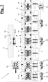
- Figure 7 shows a further, more complex configuration of a production plant (1) with a production area (3) of the type described above, a warehouse (10) and a tool store (11).
- the other provisions (9,12) are not shown for the sake of clarity.
- the warehouse (10) and the tool store (11) can be arranged on opposite sides of the production area (3), for example by having a single row of production facilities (18-21).
- Such an arrangement has the advantage that the conveyor paths (7) and the programmed conveyor tracks for tool exchange and workpiece feeding can be disentangled.
- a variant is shown in which the various
- Buffer storage for loose LAMs (6) with prepared workpiece configurations (2) is assigned to loading areas (30) of the warehouse (10).
- the conveyors (5) used for transporting the workpieces to and from the production facilities (18-22) then only load the prepared LAMs (6), with other conveyors (5) being responsible for loading the buffer storage. This ensures particularly fast changeover and loading times.
- a production area (3) can, in addition to the aforementioned types of application-flexible production facilities (18-22), also have one or more other production facilities (35) which, for example, contain a predetermined tooling and a predetermined production step which is not or only limitedly flexible.
- the production facility (35) is designed in this way. It can be designed, for example, as a geostation or framing station for vehicle bodies and have a pair of clamping frames, which may be present in multiples and can be changed on site.
- Such non-flexible or less flexible production facilities (35) can be provided, for example, for particularly large and heavy workpieces or workpiece configurations. Otherwise, they can have the same properties as the application-flexible production facilities (18-22), in particular application-flexible production means (28, 29), storage (27), etc. They can also be connected to the conveyor device (4) and also have a continuous conveyor path (7).
- a production facility (35) can also be designed as a tryout station, for example, which is used to develop a new application. Its basic structure can be similar to the uniform and standardized production facilities (18-22), whereby a manufacturing process and a control program (40) are created and tested using application-specific tools (8).
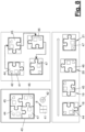
- Figure 11 shows a further variant of a production plant (1) with a production area (3) and provisions (10,11) for workpieces and application-specific tools.
- a LAM configuration area (56) is assigned to the tool store (11).
- a repair area (55) is arranged at the edge of the production area (3).
- the production plant (1) shown also contains two or more separate production devices (35), which are designed, for example, as tryout stations and are arranged close to the tool store (11).
- an intermediate storage area (57) can be present at the end of the production plant (1), where the end products are unloaded from the LAM (6) and possibly transferred to other conveyors, in particular skids.
- a painting line can be connected here, for example, whereby a painting sequence can also be created.
- the production equipment (18-21) is arranged in a Cartesian matrix with six rows (I-VI) and ten columns (01-10).
- the conveyor system (4) and its conveyor paths (7) extend between and along the rows (I-VI) and connect them to the warehouses (10) arranged to the left and right.
- On these main conveyor paths (7) for example, there is one-way traffic with two or more lanes for the conveyors (5) (not shown). The one-way direction alternates row by row.
- the main conveyor paths (7) are also connected transversely, in particular at the outer edges of the system and in the warehouse area. Furthermore, the aforementioned conveyor paths (not shown) are present in or through the production equipment (18-21).
- the total material flow of workpieces (2,2') can be divided into micro-production loops, so that the required overall sequence depends only on the order of two LAMs (6) or conveyors (5) that are sent by the warehouse manager (14) to the next production facility (18, 22).
- parking areas (53) in which one or more empty or loaded LAMs (6) can be temporarily parked.
- the parking areas (53) are each surrounded in a ring by secondary conveyor routes (7). There can be right-of-way rules on the main and secondary conveyor routes (7).
- the LAMs (6) In the case of micro-loops that are linked together and overlap in the manner described above, the LAMs (6) must enter a common production facility in a specific order due to the reloading process. This order is created and ensured at the parking area (53). There is a position (54) defined as a provisional address for the LAMs (6) on one of the main conveyor paths (7) between the rows (I-VI) at the parking areas (53).
- a type identifier (37) can be designed as a code and have several identifier fields (50, 51, 52) for different information or data.
- a first identifier field (50) can be provided for the LAM type, for example. It can be in two parts and also contain LAM-specific identification information.
- the identifier field (50) can be described by the tool store manager (15), which takes place in the LAM configuration area (56), for example.
- the second identification field (51) can contain information about the model or the respective workpiece (2,2'). This identification field (51) can be written to, for example, in the warehouse (10) during loading.
- a third identification field (52) can have a cell identifier or an identifier of the last production facility (18-22) visited. This identification field (52) is described, for example, by the process manager (40) of the respective production facility (18-22). The identification field (52) is updated in each production facility (18-22).
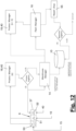
- Figure 12 shows an example of a section or module from a control and production process.
- a production process is carried out in a first production facility (18), with the process manager (40) then sending a message about the process result to the warehouse manager (14). If the process result is OK, the cell identifier is written to the identifier field (52) and the LAM (6) is sent by the warehouse manager (14) to the next production facility (19) provided in the production process. This can be done via the fleet manager (16).
- the warehouse manager (14) sends a message to the process manager (40) of the next production facility (19) about the impending arrival of the next LAM (6) and its type (A, B, C, D).
- a changeover process in particular a tool change, can already take place during the transport time and overlap with it.
- the production process then takes place in the production facility (19), with subsequent reporting of the process result to the warehouse manager (14) and updating of the characteristic map (52). The aforementioned further transport of the LAM in the intended production process.
- the LAM (6) with the workpiece (2,2') is transported to the repair area (55).
- the warehouse manager (14) initiates this via the fleet manager (16). If necessary, the fleet manager also informs the process manager (40) of the next production facility (19) accordingly.
- the warehouse manager (14) also reduces the workpiece inventory in the supply area (10) by the faulty workpiece. In the repair area (55), an attempt is made to repair the workpiece (2,2') and the process error. If the repair result is OK, the inventory in the warehouse (10) is increased again by the repaired part or the repaired part is fed directly back into the production process. If the repair result is unsatisfactory, the part is scrapped.
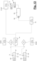
- Figure 13 shows a further aspect or building block in the system-wide control and production process in connection with the aforementioned parking area (53) of Figure 11 .
- production facilities (18,20) different workpieces are processed on different LAM types (A,B).
- LAM type (A) In the next production facility (21) the further processing and transfer of a workpiece from LAM type (A) to LAM type (B) is to take place.
- the warehouse manager (14) announces the next processing job and the entry sequence of the LAM (6) to the process manager (40) of the production facility (21).
- the LAM type (A) must enter the production facility (21) before the LAM type (B).
- Both LAMs (A, B) must now first drive to the parking area (53) in front of the production facility (21) and assigned to it. This is initiated by the warehouse manager (14) via the fleet manager (16).
- the LAMs (6) of type (A) and (B) initially control the position (54) as a provisional address. From here, the final destination is determined according to the following criteria. This destination can be the assigned production facility (21) if no preceding LAM of the arriving type (A, B) is waiting in front of this production facility (21). In this case, the production facility (21) is approached directly and without an intermediate stop in the parking area (53).
- the production facility (20) can also be approached directly by the LAM type (A) if the other following type (B) is currently in one of the places in the parking area (53) and needs to be overtaken.
- the parking area (53) is set as the destination if type (B) arrives in the wrong sequence before type (A) and is to be overtaken by the latter in the manner mentioned above to correct the sequence.
- the parking area (53) is also assigned as the destination if previous LAM types (A, B) are already in the waiting position for the production facility (21). In this case, the parking area (53) is filled up as an availability storage. It can, for example, form a buffer in the event of any process disruptions or other delays in the process or production sequence.
- the manufacturing steps (44-47) can be carried out in a single manufacturing facility (18-22).
- One and the same manufacturing facility can be involved several times within the manufacturing process. It is also possible for one and the same manufacturing facility to be used by two or more different, but synchronously running production processes.
- Another variant provides for central control of the production facilities (18-22) via the system control (13), whereby type detection of the LAM (6) can be omitted or used for verification purposes.
Landscapes
- Engineering & Computer Science (AREA)
- Mechanical Engineering (AREA)
- Physics & Mathematics (AREA)
- Manufacturing & Machinery (AREA)
- Optics & Photonics (AREA)
- Quality & Reliability (AREA)
- General Engineering & Computer Science (AREA)
- General Physics & Mathematics (AREA)
- Automation & Control Theory (AREA)
- Chemical & Material Sciences (AREA)
- Combustion & Propulsion (AREA)
- Transportation (AREA)
- Automatic Assembly (AREA)
- General Factory Administration (AREA)
- Multi-Process Working Machines And Systems (AREA)
Claims (15)
- Installation de fabrication pour des pièces (2, 2'), en particulier des pièces de carrosserie, dans laquelle l'installation de fabrication (1) présente un poste d'approvisionnement (10) pour des pièces (2, 2') et au moins un dispositif de fabrication automatique (18-22) qui présente au moins un moyen de fabrication (28, 29) commandé par programme et une zone d'usinage (26), et l'installation de fabrication (1) présente au moins deux moyens de réception de charge (6) différents l'un de l'autre qui présentent respectivement une identification de type (37),dans laquelle les moyens de réception de charge (6) de type (A, B, C, D) différent sont adaptés à différentes pièces (2, 2'),le dispositif de fabrication (18-22) présentant en outre :- une zone d'usinage (26) qui est conçue pour recevoir séquentiellement au moins deux moyens de réception de charge (6) différents l'un de l'autre,- un dispositif de détection (36) qui est conçu pour détecter une identification de type (37) d'un des moyens de réception de charge (6),- un dispositif de commande (38) qui est conçu pour déterminer le type (A, B, C, D) du moyen de réception de charge (6) à l'aide de l'identification de type (37) détectée par le dispositif de détection (36) et pour sélectionner et exécuter un programme de commande (40) pour ledit au moins un moyen de fabrication (28, 29) à l'aide du type (A, B, C, D) déterminé parmi une pluralité de programmes de commande,- dans laquelle un moyen de fabrication (29) est réalisé pour usiner une pièce (2, 2'),caractérisée- en ce qu'au niveau de la zone d'usinage (26) est disposé un moyen de fabrication (28, 29) qui est réalisé pour maintenir en suspension une pièce (2, 2') lors du processus d'usinage et pour transborder la pièce (2, 2') sur un autre moyen de réception de charge (6) de type (A, B, C, D) identique ou différent, et- en ce que les moyens de fabrication (28, 29) sont réalisés sous forme de robots industriels.
- Installation de fabrication selon la revendication 1, caractérisée en ce que le moyen de fabrication (29) présente des outils (8) échangeables, spécifiques à une application, pour exécuter le processus de fabrication respectif, qui sont réalisés par exemple sous forme d'outils d'assemblage, d'outils de transformation ou similaires.
- Installation de fabrication selon la revendication 1 ou 2, caractérisée en ce que l'installation de fabrication (1) présente au moins un dispositif de fabrication (18-22) qui est aménagé pour recevoir deux ou plusieurs moyens de réception de charge (6) de différents types avec des pièces (2, 2') ou des parties de pièces dans une séquence prédéfinie, et pour soulever et transborder une pièce (2) d'un moyen de réception de charge (6) à un autre moyen de réception de charge (6).
- Installation de fabrication selon l'une quelconque des revendications 1 à 3, caractérisée en ce que l'installation de fabrication (1) présente un dispositif de convoyage (4) qui est conçu pour déplacer au moins un type, en particulier tous les types (A, B, C, D) de moyens de réception de charge (6) à destination et en provenance du dispositif de fabrication (18-22), dans laquelle le dispositif de convoyage (4) présente au moins un moyen de convoyage (5) qui est réalisé sous forme de véhicule autonome (FTF ou AGV) ou de chariot élévateur.
- Installation de fabrication selon la revendication 4, caractérisée en ce que les moyens de réception de charge (6) sont réalisés pour recevoir un outil (8) spécifique à une application, dans laquelle l'installation de fabrication (1) présente un poste d'approvisionnement (11) raccordé au dispositif de convoyage (4) pour des outils (8) spécifiques à une application.
- Installation de fabrication selon l'une quelconque des revendications 1 à 5, caractérisée en ce que l'installation de fabrication (1) présente un poste de commande d'installation (13) comprenant au moins une unité de commande (14) réalisée sous forme de gestionnaire d'entrepôt, le gestionnaire d'entrepôt (14) commandant le séjour et le déplacement des moyens de réception de charge (6) ou du dispositif de convoyage (4).
- Installation de fabrication selon l'une quelconque des revendications 1 à 6, caractérisée en ce que l'installation de fabrication (1) présente un poste de commande d'installation (13) avec au moins une unité de commande (15) réalisée sous forme de gestionnaire d'outillage, le gestionnaire d'outillage (15) commandant le stockage des programmes de commande (40) dans les dispositifs de commande (38) des différents dispositifs de fabrication (18-22), et/ou l'équipement des différents dispositifs de fabrication (18-22) ou des moyens de fabrication (28, 29) avec des outils (8) spécifiques à une application.
- Installation de fabrication selon la revendication 7, caractérisée en ce que les dispositifs de commande (38) des dispositifs de fabrication (18-22) sont reliés au gestionnaire d'entrepôt (14).
- Installation de fabrication selon l'une quelconque des revendications 6 à 8, caractérisée en ce que l'installation de fabrication (1) est commandée de manière décentralisée, dans laquelle les dispositifs de commande (38) commandent de manière autonome l'usinage des pièces dans les dispositifs de fabrication (18-22) et signalent le début ainsi que la fin du processus d'usinage au gestionnaire d'entrepôt (14) qui commande le déroulement de la fabrication par le déplacement des moyens de réception de charge (6) ou du dispositif de convoyage (4).
- Installation de fabrication selon l'une quelconque des revendications 1 à 9, caractérisée en ce qu'un dispositif de fabrication (18-22) pour un processus primaire est relié à un dispositif de fabrication supplémentaire (67) pour un processus secondaire sur une pièce (2).
- Procédé permettant d'usiner des pièces (2, 2'), en particulier des pièces de carrosserie, dans une installation de fabrication (1) comprenant au moins un dispositif de fabrication automatique (18-22) qui présente au moins un moyen de fabrication (28, 29) commandé par programme et une zone d'usinage (26),
caractérisé en ce que le procédé présente les étapes suivantes consistant à :- déplacer un premier parmi au moins deux moyens de réception de charge (6) de type différent dans une zone d'usinage (26) d'un premier dispositif de fabrication (18) selon au moins l'une des revendications 1 à 10,- détecter et déterminer automatiquement le type (A, B, C, D) du premier moyen de réception de charge (6),- sélectionner automatiquement un programme de commande (40) associé au type (A, B, C, D) déterminé pour ledit au moins un moyen de fabrication (28, 29) parmi une pluralité de programmes de commande,- exécuter automatiquement le programme de commande (40) sélectionné,- maintenir en suspension une pièce (2, 2') lors du processus d'usinage et transborder la pièce (2, 2') sur un autre moyen de réception de charge (6) de type (A, B, C, D) identique ou différent par un moyen de fabrication (28, 29) disposé dans la zone d'usinage (26) . - Procédé selon la revendication 11, comprenant les étapes suivantes consistant à :- prendre la pièce (2) par au moins un moyen de fabrication (28, 29) sur un premier moyen de réception de charge (6),- déplacer le premier moyen de réception de charge (6) de la zone d'usinage (26) du premier dispositif de fabrication (18),- déplacer un deuxième moyen de réception de charge (6) qui est différent du premier moyen de réception de charge (6) dans la zone d'usinage (26) du premier dispositif de fabrication (18),- déposer la pièce (2) sur le deuxième moyen de réception de charge (6).
- Procédé selon la revendication 11 ou 12, comprenant l'étape suivante consistant à :- déplacer le premier ou le deuxième moyen de réception de charge (6) de la zone d'usinage (26) du premier dispositif de fabrication (18) dans la zone d'usinage (26) du deuxième dispositif de fabrication (19) .
- Procédé selon la revendication 11, 12 ou 13, caractérisé en ce que le deuxième moyen de réception de charge (6) amène une pièce supplémentaire (2') dans la zone d'usinage du premier dispositif de fabrication (18) .
- Procédé selon l'une quelconque des revendications 11 à 14, caractérisé en ce que dans un dispositif de fabrication (18-22) un processus primaire est exécuté, et dans un dispositif de fabrication supplémentaire (67) relié à celui-ci un processus secondaire est exécuté sur une pièce (2, 2').
Applications Claiming Priority (4)
| Application Number | Priority Date | Filing Date | Title |
|---|---|---|---|
| DE202015100782.5U DE202015100782U1 (de) | 2015-02-19 | 2015-02-19 | Fertigungsanlage |
| DE102015103642.8A DE102015103642A1 (de) | 2015-02-19 | 2015-03-12 | Fertigungseinrichtung, Fertigungsanlage und Verfahren |
| DE202015106459.4U DE202015106459U1 (de) | 2015-11-27 | 2015-11-27 | Fertigungseinrichtung |
| PCT/EP2016/053574 WO2016131968A1 (fr) | 2015-02-19 | 2016-02-19 | Équipement de fabrication, installation de fabrication et procédé |
Publications (2)
| Publication Number | Publication Date |
|---|---|
| EP3259097A1 EP3259097A1 (fr) | 2017-12-27 |
| EP3259097B1 true EP3259097B1 (fr) | 2024-11-06 |
Family
ID=55484953
Family Applications (2)
| Application Number | Title | Priority Date | Filing Date |
|---|---|---|---|
| EP16708368.2A Active EP3259097B1 (fr) | 2015-02-19 | 2016-02-19 | Installation de fabrication et procédé |
| EP16708367.4A Active EP3259096B1 (fr) | 2015-02-19 | 2016-02-19 | Installation et procédé de fabrication |
Family Applications After (1)
| Application Number | Title | Priority Date | Filing Date |
|---|---|---|---|
| EP16708367.4A Active EP3259096B1 (fr) | 2015-02-19 | 2016-02-19 | Installation et procédé de fabrication |
Country Status (7)
| Country | Link |
|---|---|
| US (2) | US10427255B2 (fr) |
| EP (2) | EP3259097B1 (fr) |
| CN (2) | CN107405736B (fr) |
| ES (1) | ES2758078T3 (fr) |
| HU (1) | HUE046384T2 (fr) |
| PL (1) | PL3259096T3 (fr) |
| WO (2) | WO2016131968A1 (fr) |
Families Citing this family (43)
| Publication number | Priority date | Publication date | Assignee | Title |
|---|---|---|---|---|
| FR3034410B1 (fr) * | 2015-04-02 | 2020-10-23 | Gebo Packaging Solutions France | Dispositif de convoyage par chariot autonome |
| DE202017101643U1 (de) | 2017-03-21 | 2018-05-08 | Kuka Systems Gmbh | Fertigungsstation |
| WO2018178876A1 (fr) | 2017-03-27 | 2018-10-04 | Clearpath Robotics, Inc. | Systèmes et procédés de fabrication flexible au moyen de véhicules autonomes |
| WO2018178875A1 (fr) | 2017-03-27 | 2018-10-04 | Clearpath Robotics, Inc. | Systèmes et procédés de réapprovisionnement autonome |
| US10990919B2 (en) | 2017-03-27 | 2021-04-27 | Clearpath Robotics Inc. | Systems and methods for autonomous lineside parts delivery to an assembly line process |
| DE202017102155U1 (de) | 2017-04-11 | 2018-07-24 | Kuka Systems Gmbh | Fertigungsstation |
| KR102435779B1 (ko) * | 2017-07-28 | 2022-08-23 | 에이비비 슈바이쯔 아게 | 로봇 조립 방법 |
| DE102017007420A1 (de) | 2017-08-05 | 2019-02-07 | Audi Ag | Fertigungsanlage mit fahrerlosen Transportfahrzeugen und verbesserter Werkstückpositionierung in den Fertigungsstationen |
| DE102018203880A1 (de) * | 2018-03-14 | 2019-09-19 | Homag Automation Gmbh | Verfahren zum Handhaben eines Werkstücks und System |
| JP7300468B2 (ja) | 2018-06-08 | 2023-06-29 | アタボティックス インコーポレイテッド | 保管格子と外部作業ステーションとの間で共通ロボット車両隊を共有する保管及び回収システム |
| JP7156897B2 (ja) * | 2018-10-10 | 2022-10-19 | シチズン時計株式会社 | 工作機械 |
| CN111098087A (zh) * | 2018-10-25 | 2020-05-05 | 重庆铁马工业集团有限公司 | 一种军用重载车辆底盘变速箱壳体柔性加工工艺 |
| CN113195156B (zh) * | 2018-12-19 | 2023-04-18 | 阿特拉斯·科普柯工业技术公司 | 用于设置电动工具的操作模式和/或关联结果值的方法、电动工具以及计算机程序 |
| CN109848707B (zh) * | 2019-01-19 | 2020-05-01 | 常德市佳鸿机械有限责任公司 | 一种挖机油缸缸盖的自动生产系统及方法 |
| CN109676252A (zh) * | 2019-02-02 | 2019-04-26 | 宁波吉利汽车研究开发有限公司 | 激光工作站 |
| CN109807676A (zh) * | 2019-02-12 | 2019-05-28 | 东华大学 | 一种自动化工件搬运载板系统 |
| JP2022531714A (ja) | 2019-05-09 | 2022-07-08 | デュール システムズ アーゲー | 分析方法及びそのための装置 |
| EP3966647B1 (fr) | 2019-05-09 | 2025-10-29 | Dürr Systems AG | Procédé d'analyse et dispositifs correspondants |
| DE112020002299A5 (de) * | 2019-05-09 | 2022-03-03 | Dürr Systems Ag | Verfahren zur Analyse von Qualitätsmängeln |
| JP2022531717A (ja) * | 2019-05-09 | 2022-07-08 | デュール システムズ アーゲー | 工作物を管理する方法、管理設備及び処理設備 |
| PT3966650T (pt) * | 2019-05-09 | 2024-04-04 | Duerr Systems Ag | Processo para o controlo e pós-tratamento de peças de trabalho, instalação de controlo e instalação de tratamento |
| EP3983177B8 (fr) | 2019-06-11 | 2026-02-11 | Lafayette Systems Canada ULC | Système de fabrication comprenant une structure de stockage interconnectée et des cellules de fabrication partageant une flotte robotique commune |
| CN110717707A (zh) * | 2019-09-11 | 2020-01-21 | 深圳市铭华航电工艺技术有限公司 | 应用于生产现场的物品运输系统和方法 |
| CN113146362A (zh) * | 2020-01-22 | 2021-07-23 | 广东兴发铝业有限公司 | 具有缓存分拣区的立式铝型材处理系统 |
| CN113148543A (zh) * | 2020-01-22 | 2021-07-23 | 广东兴发铝业有限公司 | 具有悬吊输送线的立式铝型材处理系统 |
| CN113148579A (zh) * | 2020-01-22 | 2021-07-23 | 广东兴发铝业有限公司 | 具有智能悬吊输送线的立式铝型材处理系统 |
| US11460862B2 (en) | 2020-02-03 | 2022-10-04 | Ford Global Technologies, Llc | Deployable mobile transporters for easy plant reconfiguration |
| EP3862131B1 (fr) * | 2020-02-07 | 2024-10-30 | Maas Innovation S.r.l. | Installation de traitement de produits |
| DE102020116124B3 (de) * | 2020-06-18 | 2021-11-25 | Dr. Ing. H.C. F. Porsche Aktiengesellschaft | Aufnahmeanordnungslager für mindestens eine Fertigungsstation sowie Fertigungsstation |
| DE102020116123B4 (de) * | 2020-06-18 | 2025-01-02 | Dr. Ing. H.C. F. Porsche Aktiengesellschaft | Fertigungsstation für Werkstücke, insbesondere Karosserieteile, sowie Fertigungsanlage |
| US11790125B2 (en) | 2020-07-09 | 2023-10-17 | Peyman Poostchi | System and method for automated production of buildings and building components |
| CN112222718B (zh) * | 2020-09-22 | 2022-08-02 | 中车长春轨道客车股份有限公司 | 一种车顶柔性组焊夹具系统 |
| DE102020216382A1 (de) | 2020-12-21 | 2022-06-23 | Siemens Mobility GmbH | Verfahren zur modularen Herstellung eines Wagenkasten-Rohbaus eines Schienenfahrzeugs und Wagenkasten-Rohbau |
| TWI755299B (zh) | 2021-03-10 | 2022-02-11 | 財團法人工業技術研究院 | 產線排程方法、產線系統及電腦可讀取媒體 |
| CN117280365A (zh) * | 2021-04-29 | 2023-12-22 | 西门子工业软件有限公司 | 用于将agv车辆分配在工厂位置的方法和系统 |
| CN113371457B (zh) * | 2021-06-29 | 2022-09-02 | 延锋海纳川汽车饰件系统有限公司 | 一种生产线产品自动搬运系统及搬运方法 |
| DE102021004658A1 (de) | 2021-09-14 | 2021-11-11 | Daimler Ag | System zur Prduktion von Elektrofahrzeugen |
| TWI798950B (zh) * | 2021-11-22 | 2023-04-11 | 泰科動力股份有限公司 | 細胞生產模式下的生產系統、工作站以及平板 |
| DE102023108300A1 (de) * | 2023-03-31 | 2024-10-02 | Bayerische Motoren Werke Aktiengesellschaft | Anlage zur Prozessierung von Werkstücken zur Herstellung von Kraftfahrzeugen |
| CN116175202B (zh) * | 2023-04-24 | 2023-08-15 | 山东德晟机器人股份有限公司 | 减速器壳体总成自动化加工检测生产线 |
| CN117284560B (zh) * | 2023-08-22 | 2026-04-28 | 茌平信源环保建材有限公司 | 一种综合龙骨生产线系统 |
| CN117047065A (zh) * | 2023-09-01 | 2023-11-14 | 中信戴卡股份有限公司 | 一种转向节压铸毛坯及其后处理工艺 |
| CN117699448A (zh) * | 2024-01-04 | 2024-03-15 | 义乌清越光电科技有限公司 | 一种自动生产线系统 |
Citations (2)
| Publication number | Priority date | Publication date | Assignee | Title |
|---|---|---|---|---|
| JP2006127309A (ja) * | 2004-10-29 | 2006-05-18 | Mazda Motor Corp | 生産ラインの生産指示システム |
| US20070024463A1 (en) * | 2005-07-26 | 2007-02-01 | Rockwell Automation Technologies, Inc. | RFID tag data affecting automation controller with internal database |
Family Cites Families (53)
| Publication number | Priority date | Publication date | Assignee | Title |
|---|---|---|---|---|
| DE142162C (fr) | ||||
| DE158371C (fr) | ||||
| US4069764A (en) * | 1974-03-28 | 1978-01-24 | Regie Nationale Des Usines Renault | Manufacturing production line and method |
| DE3209222C2 (de) * | 1982-03-13 | 1985-04-25 | Kuka Schweissanlagen + Roboter Gmbh, 8900 Augsburg | Bearbeitungsstation in einer durch Verkettung von einzelnen Bearbeitungsstationen gebildeten Transferstraße |
| DE3408720A1 (de) | 1984-03-09 | 1985-09-19 | Maho Werkzeugmaschinenbau Babel & Co, 8962 Pfronten | Gleisloses flurfoerdersystem |
| DE3536014A1 (de) | 1984-10-16 | 1986-04-17 | Volkswagen AG, 3180 Wolfsburg | Fertigungsstation, insbesondere fuer kraftfahrzeug-karosserien |
| JPH0829467B2 (ja) * | 1985-04-30 | 1996-03-27 | インタ−ナショナル ビジネス マシ−ンズ コ−ポレ−ション | 組立て装置 |
| US4722653A (en) * | 1985-04-30 | 1988-02-02 | Ibm Corporation | Material handling for automated assembly facility |
| US4894908A (en) | 1987-08-20 | 1990-01-23 | Gmf Robotics Corporation | Method for automated assembly of assemblies such as automotive assemblies and system utilizing same |
| JP2831999B2 (ja) * | 1987-12-01 | 1998-12-02 | マツダ株式会社 | 自動車組立ラインの足回り部組付装置 |
| DE8813875U1 (de) * | 1988-11-05 | 1988-12-22 | Fa. Carl Zeiss, 7920 Heidenheim | Taster für Koordinatenmeßgeräte |
| KR970007308B1 (ko) * | 1992-03-19 | 1997-05-07 | 마쓰다 가부시끼가이샤 | 자동차 가공물 조립방법 및 조립용 부품운반차 |
| JPH07299705A (ja) | 1994-05-06 | 1995-11-14 | Kubota Corp | 自動処理施設 |
| AT406030B (de) | 1994-11-24 | 2000-01-25 | Wolfgang Dipl Ing D Stubenvoll | Autonome, selbstfahrende, spurungebundene, koppelbare werkstückträgerwagen |
| FR2757819B1 (fr) | 1996-12-31 | 1999-01-22 | Renault | Procede et dispositif de montage d'elements de carrosserie de vehicules automobiles |
| JPH1158185A (ja) | 1997-08-19 | 1999-03-02 | Hirata Corp | ワーク搬送方法及びワーク搬送装置 |
| EP0933161B1 (fr) | 1998-02-03 | 2001-04-04 | COMAU S.p.A. | Appareillage de soudage par points d'éléments de carrosserie de véhicules |
| JP3673117B2 (ja) | 1999-06-14 | 2005-07-20 | 和泉電気株式会社 | 組立装置とそのためのトレイシステム |
| JP2001162465A (ja) * | 1999-09-27 | 2001-06-19 | Denso Corp | 組立加工装置 |
| DE19948139A1 (de) * | 1999-10-07 | 2001-04-12 | Volkswagen Ag | Flexibles Fertigungssystem |
| US20030110618A1 (en) * | 2001-12-14 | 2003-06-19 | Magnuson James M. | Multi-task steel process device |
| US6817829B2 (en) * | 2001-12-25 | 2004-11-16 | Komatsu Ltd. | Work loading method for automatic palletizer, work loading method, work loading apparatus and attachment replacing method thereof |
| DE20304022U1 (de) * | 2003-03-12 | 2004-07-22 | Kuka Schweissanlagen Gmbh | Fertigungsanlage für Bauteile, insbesondere Karosseriebauteile |
| DE202005001780U1 (de) | 2005-02-03 | 2006-06-08 | Kuka Schweissanlagen Gmbh | Fertigungseinrichtung für Bauteile |
| DE102005042179B4 (de) | 2005-09-06 | 2010-07-08 | Thyssenkrupp Drauz Nothelfer Gmbh | Flexible Fertigungszelle für die Bearbeitung von Bauteilen, insbesondere von Fahrzeugkarosserien |
| DE102005059426A1 (de) | 2005-12-13 | 2007-06-14 | Wilhelm Karmann Gmbh | Bearbeitungsstation einer Fertigungsanlage |
| DE102006003555B4 (de) * | 2006-01-25 | 2010-01-21 | Edag Gmbh & Co. Kgaa | Steuerung für eine Werkzeug-Sensor-Vorrichtung |
| US20080131255A1 (en) * | 2006-11-30 | 2008-06-05 | Transbotics Corporation | Palletizing systems and methods |
| CN101439467B (zh) * | 2007-11-23 | 2012-09-12 | 丁晓跃 | 金属形材辊轧与加工设备及其网络控制系统 |
| DE102008009995A1 (de) * | 2008-02-19 | 2009-08-20 | Kuka Systems Gmbh | Verfahren und Vorrichtung zum Transportieren von Werkstücken |
| US8201723B2 (en) * | 2008-03-12 | 2012-06-19 | Comau, Inc. | Robotic high density welding body shop |
| US8713780B2 (en) * | 2008-05-13 | 2014-05-06 | Comau, Inc. | High density welding subassembly machine |
| CA2690120C (fr) * | 2008-06-11 | 2010-11-09 | Jeffrey Douglas Gaudette | Appareils, systemes et procedes de fixation de pieces |
| DE202008012602U1 (de) | 2008-09-22 | 2010-03-04 | Kuka Systems Gmbh | Bearbeitungsstation |
| DE202009005237U1 (de) | 2009-09-04 | 2011-01-20 | Kuka Systems Gmbh | Bearbeitungseinrichtung |
| US8626329B2 (en) * | 2009-11-20 | 2014-01-07 | Agr Automation Ltd. | Product assembly system and control software |
| SE534719C2 (sv) * | 2009-12-08 | 2011-11-29 | Vaederstad Verken Ab | Förfarande och system för distribution av komponenter till materialsatser |
| DE102010055959A1 (de) * | 2010-12-23 | 2012-06-28 | Daimler Ag | Verfahren zum Montieren von Kraftwagen |
| PL2715465T3 (pl) | 2011-06-03 | 2019-05-31 | Comau Llc | Zintegrowany system konstruowania i dostarczania części pojazdów |
| RS55439B1 (sr) | 2011-08-01 | 2017-04-28 | Comau Spa | Sistem za sklapanje komponente na strukturu tela motornog vozila |
| KR101272938B1 (ko) * | 2011-10-13 | 2013-06-11 | 기아자동차주식회사 | 차량용 패널의 롤러 헤밍 시스템 |
| JP2015500746A (ja) * | 2011-12-09 | 2015-01-08 | ダイムラー・アクチェンゲゼルシャフトDaimler AG | 製造プラントの運転方法 |
| ITTO20120241A1 (it) * | 2012-03-19 | 2013-09-20 | Cpm S P A | Impianto per assemblare parti meccaniche su scocche di veicoli |
| ES2733453T3 (es) * | 2012-05-29 | 2019-11-29 | Comau Llc | Procedimientos de uso de un carro guiado automatizado |
| US9943937B2 (en) * | 2012-09-28 | 2018-04-17 | The Boeing Company | System and method for manufacturing a wing panel |
| KR101438613B1 (ko) * | 2012-12-17 | 2014-09-05 | 현대자동차 주식회사 | 차체 루프 조립용 플로팅 행어 |
| KR101416373B1 (ko) * | 2012-12-17 | 2014-07-08 | 기아자동차 주식회사 | 차량 조립 시스템 |
| US9833194B2 (en) * | 2013-03-15 | 2017-12-05 | Stryker Corporation | Patient support apparatus with remote communications |
| KR101427973B1 (ko) | 2013-07-09 | 2014-08-07 | 현대자동차 주식회사 | 차량 조립용 체결 보증 시스템 및 그 제어 방법 |
| US20150066164A1 (en) * | 2013-08-27 | 2015-03-05 | FreePoint Technologies Inc. | System and method for dynamically reporting manufacturing data in a spreadsheet format |
| CN104723115A (zh) * | 2013-12-19 | 2015-06-24 | 常州创胜特尔数控机床设备有限公司 | 一种机器人辅助全自动加工生产线 |
| CN204160167U (zh) * | 2014-09-26 | 2015-02-18 | 温岭市装配设备成套有限公司 | 汽车单向器装配设备 |
| JP6450708B2 (ja) * | 2016-05-16 | 2019-01-09 | ファナック株式会社 | 複数の製造セルの間で加工情報を処理する情報処理装置 |
-
2016
- 2016-02-19 US US15/552,004 patent/US10427255B2/en not_active Expired - Fee Related
- 2016-02-19 PL PL16708367T patent/PL3259096T3/pl unknown
- 2016-02-19 EP EP16708368.2A patent/EP3259097B1/fr active Active
- 2016-02-19 EP EP16708367.4A patent/EP3259096B1/fr active Active
- 2016-02-19 WO PCT/EP2016/053574 patent/WO2016131968A1/fr not_active Ceased
- 2016-02-19 HU HUE16708367A patent/HUE046384T2/hu unknown
- 2016-02-19 US US15/552,047 patent/US10744605B2/en not_active Expired - Fee Related
- 2016-02-19 CN CN201680011260.6A patent/CN107405736B/zh active Active
- 2016-02-19 WO PCT/EP2016/053562 patent/WO2016131961A1/fr not_active Ceased
- 2016-02-19 ES ES16708367T patent/ES2758078T3/es active Active
- 2016-02-19 CN CN201680011279.0A patent/CN107257720B/zh active Active
Patent Citations (2)
| Publication number | Priority date | Publication date | Assignee | Title |
|---|---|---|---|---|
| JP2006127309A (ja) * | 2004-10-29 | 2006-05-18 | Mazda Motor Corp | 生産ラインの生産指示システム |
| US20070024463A1 (en) * | 2005-07-26 | 2007-02-01 | Rockwell Automation Technologies, Inc. | RFID tag data affecting automation controller with internal database |
Also Published As
| Publication number | Publication date |
|---|---|
| EP3259096B1 (fr) | 2019-09-04 |
| US10427255B2 (en) | 2019-10-01 |
| CN107257720B (zh) | 2020-11-13 |
| CN107257720A (zh) | 2017-10-17 |
| US20180036845A1 (en) | 2018-02-08 |
| EP3259097A1 (fr) | 2017-12-27 |
| WO2016131968A1 (fr) | 2016-08-25 |
| CN107405736A (zh) | 2017-11-28 |
| EP3259096A1 (fr) | 2017-12-27 |
| ES2758078T3 (es) | 2020-05-04 |
| US20180029178A1 (en) | 2018-02-01 |
| WO2016131961A1 (fr) | 2016-08-25 |
| US10744605B2 (en) | 2020-08-18 |
| HUE046384T2 (hu) | 2020-03-30 |
| PL3259096T3 (pl) | 2020-05-18 |
| CN107405736B (zh) | 2020-07-28 |
Similar Documents
| Publication | Publication Date | Title |
|---|---|---|
| EP3259096B1 (fr) | Installation et procédé de fabrication | |
| DE102015103642A1 (de) | Fertigungseinrichtung, Fertigungsanlage und Verfahren | |
| EP3380268B1 (fr) | Dispositif de fabrication et procédé de fabrication | |
| EP3463745B1 (fr) | Station de fabrication et procédé de fabrication | |
| EP3114017B1 (fr) | Poste de production, usine de production et procédé | |
| EP3445526B1 (fr) | Installation de fabrication et procédé de fabrication | |
| EP3415447B1 (fr) | Installation et procede destines a traiter des lentilles optiques | |
| DE102017000640C5 (de) | Beschichtungsanlage und Verfahren zum Betreiben einer Beschichtungsanlage | |
| EP1601492B1 (fr) | Installation de production de composants, en particulier de composants de carrosserie | |
| EP3114018B2 (fr) | Installation de production, système de transport et procédé | |
| EP2392981B1 (fr) | Procédé de commande d'une voie de fabrication cadencée | |
| DE102014102990B4 (de) | Fertigungsstation | |
| DE102016110820A1 (de) | Rendezvous-Kommissionierung mit örtlich variabler Kommissionierstation | |
| EP2062837A1 (fr) | Procédé de fonctionnement d'une installation de manutention et installation de manutention | |
| DE102007047279A1 (de) | Fertigungsanlage, insbesondere für Karosserieeinheiten | |
| WO2017080639A1 (fr) | Procédé, installation et système pour le traitement de lentilles optiques | |
| DE202014101002U1 (de) | Fertigungsstation | |
| EP4305499A1 (fr) | Procédé de commande de véhicules de transport et système de transport | |
| AT526152A4 (de) | Fertigungsanlage | |
| DE102020213540A1 (de) | Fertigungsanlage zur Serienfertigung von Kraftfahrzeugen und Verfahren zum Fertigen eines Kraftfahrzeugs | |
| DE102017222425A1 (de) | Transportsystem, Verfahren zur Steuerung des Transportsystems und Transportsystemanordnung | |
| DE102023102956A1 (de) | Autonom reorganisierbare Produktion | |
| WO2024199963A1 (fr) | Système pour le traitement de pièces pour la production de véhicules automobiles |
Legal Events
| Date | Code | Title | Description |
|---|---|---|---|
| STAA | Information on the status of an ep patent application or granted ep patent |
Free format text: STATUS: THE INTERNATIONAL PUBLICATION HAS BEEN MADE |
|
| PUAI | Public reference made under article 153(3) epc to a published international application that has entered the european phase |
Free format text: ORIGINAL CODE: 0009012 |
|
| STAA | Information on the status of an ep patent application or granted ep patent |
Free format text: STATUS: REQUEST FOR EXAMINATION WAS MADE |
|
| 17P | Request for examination filed |
Effective date: 20170905 |
|
| AK | Designated contracting states |
Kind code of ref document: A1 Designated state(s): AL AT BE BG CH CY CZ DE DK EE ES FI FR GB GR HR HU IE IS IT LI LT LU LV MC MK MT NL NO PL PT RO RS SE SI SK SM TR |
|
| AX | Request for extension of the european patent |
Extension state: BA ME |
|
| DAV | Request for validation of the european patent (deleted) | ||
| DAX | Request for extension of the european patent (deleted) | ||
| STAA | Information on the status of an ep patent application or granted ep patent |
Free format text: STATUS: EXAMINATION IS IN PROGRESS |
|
| 17Q | First examination report despatched |
Effective date: 20200924 |
|
| P01 | Opt-out of the competence of the unified patent court (upc) registered |
Effective date: 20230528 |
|
| GRAP | Despatch of communication of intention to grant a patent |
Free format text: ORIGINAL CODE: EPIDOSNIGR1 |
|
| STAA | Information on the status of an ep patent application or granted ep patent |
Free format text: STATUS: GRANT OF PATENT IS INTENDED |
|
| INTG | Intention to grant announced |
Effective date: 20240606 |
|
| GRAS | Grant fee paid |
Free format text: ORIGINAL CODE: EPIDOSNIGR3 |
|
| GRAA | (expected) grant |
Free format text: ORIGINAL CODE: 0009210 |
|
| STAA | Information on the status of an ep patent application or granted ep patent |
Free format text: STATUS: THE PATENT HAS BEEN GRANTED |
|
| AK | Designated contracting states |
Kind code of ref document: B1 Designated state(s): AL AT BE BG CH CY CZ DE DK EE ES FI FR GB GR HR HU IE IS IT LI LT LU LV MC MK MT NL NO PL PT RO RS SE SI SK SM TR |
|
| REG | Reference to a national code |
Ref country code: GB Ref legal event code: FG4D Free format text: NOT ENGLISH |
|
| REG | Reference to a national code |
Ref country code: CH Ref legal event code: EP |
|
| REG | Reference to a national code |
Ref country code: DE Ref legal event code: R096 Ref document number: 502016016782 Country of ref document: DE |
|
| REG | Reference to a national code |
Ref country code: IE Ref legal event code: FG4D Free format text: LANGUAGE OF EP DOCUMENT: GERMAN |
|
| REG | Reference to a national code |
Ref country code: LT Ref legal event code: MG9D |
|
| REG | Reference to a national code |
Ref country code: NL Ref legal event code: MP Effective date: 20241106 |
|
| PG25 | Lapsed in a contracting state [announced via postgrant information from national office to epo] |
Ref country code: HR Free format text: LAPSE BECAUSE OF FAILURE TO SUBMIT A TRANSLATION OF THE DESCRIPTION OR TO PAY THE FEE WITHIN THE PRESCRIBED TIME-LIMIT Effective date: 20241106 Ref country code: PT Free format text: LAPSE BECAUSE OF FAILURE TO SUBMIT A TRANSLATION OF THE DESCRIPTION OR TO PAY THE FEE WITHIN THE PRESCRIBED TIME-LIMIT Effective date: 20250306 Ref country code: IS Free format text: LAPSE BECAUSE OF FAILURE TO SUBMIT A TRANSLATION OF THE DESCRIPTION OR TO PAY THE FEE WITHIN THE PRESCRIBED TIME-LIMIT Effective date: 20250306 |
|
| PG25 | Lapsed in a contracting state [announced via postgrant information from national office to epo] |
Ref country code: FI Free format text: LAPSE BECAUSE OF FAILURE TO SUBMIT A TRANSLATION OF THE DESCRIPTION OR TO PAY THE FEE WITHIN THE PRESCRIBED TIME-LIMIT Effective date: 20241106 Ref country code: NL Free format text: LAPSE BECAUSE OF FAILURE TO SUBMIT A TRANSLATION OF THE DESCRIPTION OR TO PAY THE FEE WITHIN THE PRESCRIBED TIME-LIMIT Effective date: 20241106 |
|
| PG25 | Lapsed in a contracting state [announced via postgrant information from national office to epo] |
Ref country code: BG Free format text: LAPSE BECAUSE OF FAILURE TO SUBMIT A TRANSLATION OF THE DESCRIPTION OR TO PAY THE FEE WITHIN THE PRESCRIBED TIME-LIMIT Effective date: 20241106 |
|
| PG25 | Lapsed in a contracting state [announced via postgrant information from national office to epo] |
Ref country code: ES Free format text: LAPSE BECAUSE OF FAILURE TO SUBMIT A TRANSLATION OF THE DESCRIPTION OR TO PAY THE FEE WITHIN THE PRESCRIBED TIME-LIMIT Effective date: 20241106 |
|
| PG25 | Lapsed in a contracting state [announced via postgrant information from national office to epo] |
Ref country code: NO Free format text: LAPSE BECAUSE OF FAILURE TO SUBMIT A TRANSLATION OF THE DESCRIPTION OR TO PAY THE FEE WITHIN THE PRESCRIBED TIME-LIMIT Effective date: 20250206 |
|
| PG25 | Lapsed in a contracting state [announced via postgrant information from national office to epo] |
Ref country code: LV Free format text: LAPSE BECAUSE OF FAILURE TO SUBMIT A TRANSLATION OF THE DESCRIPTION OR TO PAY THE FEE WITHIN THE PRESCRIBED TIME-LIMIT Effective date: 20241106 Ref country code: GR Free format text: LAPSE BECAUSE OF FAILURE TO SUBMIT A TRANSLATION OF THE DESCRIPTION OR TO PAY THE FEE WITHIN THE PRESCRIBED TIME-LIMIT Effective date: 20250207 |
|
| PG25 | Lapsed in a contracting state [announced via postgrant information from national office to epo] |
Ref country code: PL Free format text: LAPSE BECAUSE OF FAILURE TO SUBMIT A TRANSLATION OF THE DESCRIPTION OR TO PAY THE FEE WITHIN THE PRESCRIBED TIME-LIMIT Effective date: 20241106 |
|
| PG25 | Lapsed in a contracting state [announced via postgrant information from national office to epo] |
Ref country code: RS Free format text: LAPSE BECAUSE OF FAILURE TO SUBMIT A TRANSLATION OF THE DESCRIPTION OR TO PAY THE FEE WITHIN THE PRESCRIBED TIME-LIMIT Effective date: 20250206 |
|
| PG25 | Lapsed in a contracting state [announced via postgrant information from national office to epo] |
Ref country code: SM Free format text: LAPSE BECAUSE OF FAILURE TO SUBMIT A TRANSLATION OF THE DESCRIPTION OR TO PAY THE FEE WITHIN THE PRESCRIBED TIME-LIMIT Effective date: 20241106 |
|
| PG25 | Lapsed in a contracting state [announced via postgrant information from national office to epo] |
Ref country code: DK Free format text: LAPSE BECAUSE OF FAILURE TO SUBMIT A TRANSLATION OF THE DESCRIPTION OR TO PAY THE FEE WITHIN THE PRESCRIBED TIME-LIMIT Effective date: 20241106 |
|
| PG25 | Lapsed in a contracting state [announced via postgrant information from national office to epo] |
Ref country code: EE Free format text: LAPSE BECAUSE OF FAILURE TO SUBMIT A TRANSLATION OF THE DESCRIPTION OR TO PAY THE FEE WITHIN THE PRESCRIBED TIME-LIMIT Effective date: 20241106 |
|
| PG25 | Lapsed in a contracting state [announced via postgrant information from national office to epo] |
Ref country code: RO Free format text: LAPSE BECAUSE OF FAILURE TO SUBMIT A TRANSLATION OF THE DESCRIPTION OR TO PAY THE FEE WITHIN THE PRESCRIBED TIME-LIMIT Effective date: 20241106 |
|
| PG25 | Lapsed in a contracting state [announced via postgrant information from national office to epo] |
Ref country code: SK Free format text: LAPSE BECAUSE OF FAILURE TO SUBMIT A TRANSLATION OF THE DESCRIPTION OR TO PAY THE FEE WITHIN THE PRESCRIBED TIME-LIMIT Effective date: 20241106 |
|
| PG25 | Lapsed in a contracting state [announced via postgrant information from national office to epo] |
Ref country code: CZ Free format text: LAPSE BECAUSE OF FAILURE TO SUBMIT A TRANSLATION OF THE DESCRIPTION OR TO PAY THE FEE WITHIN THE PRESCRIBED TIME-LIMIT Effective date: 20241106 |
|
| PG25 | Lapsed in a contracting state [announced via postgrant information from national office to epo] |
Ref country code: IT Free format text: LAPSE BECAUSE OF FAILURE TO SUBMIT A TRANSLATION OF THE DESCRIPTION OR TO PAY THE FEE WITHIN THE PRESCRIBED TIME-LIMIT Effective date: 20241106 |
|
| REG | Reference to a national code |
Ref country code: DE Ref legal event code: R097 Ref document number: 502016016782 Country of ref document: DE |
|
| PG25 | Lapsed in a contracting state [announced via postgrant information from national office to epo] |
Ref country code: SE Free format text: LAPSE BECAUSE OF FAILURE TO SUBMIT A TRANSLATION OF THE DESCRIPTION OR TO PAY THE FEE WITHIN THE PRESCRIBED TIME-LIMIT Effective date: 20241106 |
|
| PLBE | No opposition filed within time limit |
Free format text: ORIGINAL CODE: 0009261 |
|
| STAA | Information on the status of an ep patent application or granted ep patent |
Free format text: STATUS: NO OPPOSITION FILED WITHIN TIME LIMIT |
|
| PG25 | Lapsed in a contracting state [announced via postgrant information from national office to epo] |
Ref country code: MC Free format text: LAPSE BECAUSE OF FAILURE TO SUBMIT A TRANSLATION OF THE DESCRIPTION OR TO PAY THE FEE WITHIN THE PRESCRIBED TIME-LIMIT Effective date: 20241106 |
|
| 26N | No opposition filed |
Effective date: 20250807 |
|
| PG25 | Lapsed in a contracting state [announced via postgrant information from national office to epo] |
Ref country code: LU Free format text: LAPSE BECAUSE OF NON-PAYMENT OF DUE FEES Effective date: 20250219 |
|
| REG | Reference to a national code |
Ref country code: BE Ref legal event code: MM Effective date: 20250228 |
|
| PGFP | Annual fee paid to national office [announced via postgrant information from national office to epo] |
Ref country code: FR Payment date: 20251208 Year of fee payment: 11 |
|
| PG25 | Lapsed in a contracting state [announced via postgrant information from national office to epo] |
Ref country code: BE Free format text: LAPSE BECAUSE OF NON-PAYMENT OF DUE FEES Effective date: 20250228 |
|
| PG25 | Lapsed in a contracting state [announced via postgrant information from national office to epo] |
Ref country code: IE Free format text: LAPSE BECAUSE OF NON-PAYMENT OF DUE FEES Effective date: 20250219 |
|
| REG | Reference to a national code |
Ref country code: CH Ref legal event code: U11 Free format text: ST27 STATUS EVENT CODE: U-0-0-U10-U11 (AS PROVIDED BY THE NATIONAL OFFICE) Effective date: 20260301 |
|
| PGFP | Annual fee paid to national office [announced via postgrant information from national office to epo] |
Ref country code: GB Payment date: 20260106 Year of fee payment: 11 |
|
| PGFP | Annual fee paid to national office [announced via postgrant information from national office to epo] |
Ref country code: DE Payment date: 20251224 Year of fee payment: 11 |
|
| PG25 | Lapsed in a contracting state [announced via postgrant information from national office to epo] |
Ref country code: AT Free format text: LAPSE BECAUSE OF NON-PAYMENT OF DUE FEES Effective date: 20250219 |
|
| REG | Reference to a national code |
Ref country code: AT Ref legal event code: MM01 Ref document number: 1738852 Country of ref document: AT Kind code of ref document: T Effective date: 20250219 |
|
| PGFP | Annual fee paid to national office [announced via postgrant information from national office to epo] |
Ref country code: CH Payment date: 20260301 Year of fee payment: 11 |