EP0368058A1 - Poste de remplissage - Google Patents
Poste de remplissage Download PDFInfo
- Publication number
- EP0368058A1 EP0368058A1 EP89119470A EP89119470A EP0368058A1 EP 0368058 A1 EP0368058 A1 EP 0368058A1 EP 89119470 A EP89119470 A EP 89119470A EP 89119470 A EP89119470 A EP 89119470A EP 0368058 A1 EP0368058 A1 EP 0368058A1
- Authority
- EP
- European Patent Office
- Prior art keywords
- hollow glass
- filling station
- nozzles
- steam jet
- mouthpieces
- Prior art date
- Legal status (The legal status is an assumption and is not a legal conclusion. Google has not performed a legal analysis and makes no representation as to the accuracy of the status listed.)
- Withdrawn
Links
- 239000011521 glass Substances 0.000 claims abstract description 77
- 238000004140 cleaning Methods 0.000 claims abstract description 52
- 238000005406 washing Methods 0.000 claims abstract description 6
- 238000002372 labelling Methods 0.000 claims abstract description 4
- XLYOFNOQVPJJNP-UHFFFAOYSA-N water Chemical class O XLYOFNOQVPJJNP-UHFFFAOYSA-N 0.000 claims description 11
- 230000006698 induction Effects 0.000 claims description 8
- 238000011144 upstream manufacturing Methods 0.000 claims description 4
- 239000000356 contaminant Substances 0.000 claims description 2
- 235000013618 yogurt Nutrition 0.000 claims description 2
- 239000002966 varnish Substances 0.000 claims 1
- 238000007789 sealing Methods 0.000 abstract description 5
- 239000004922 lacquer Substances 0.000 description 5
- 239000000463 material Substances 0.000 description 5
- 239000011888 foil Substances 0.000 description 4
- 238000011179 visual inspection Methods 0.000 description 4
- 238000001816 cooling Methods 0.000 description 2
- 239000000945 filler Substances 0.000 description 2
- 230000002411 adverse Effects 0.000 description 1
- XAGFODPZIPBFFR-UHFFFAOYSA-N aluminium Chemical compound [Al] XAGFODPZIPBFFR-UHFFFAOYSA-N 0.000 description 1
- 229910052782 aluminium Inorganic materials 0.000 description 1
- 238000010276 construction Methods 0.000 description 1
- 238000005187 foaming Methods 0.000 description 1
- 230000001771 impaired effect Effects 0.000 description 1
- 238000000034 method Methods 0.000 description 1
- 239000003973 paint Substances 0.000 description 1
- 229920006395 saturated elastomer Polymers 0.000 description 1
Images


Classifications
-
- B—PERFORMING OPERATIONS; TRANSPORTING
- B65—CONVEYING; PACKING; STORING; HANDLING THIN OR FILAMENTARY MATERIAL
- B65B—MACHINES, APPARATUS OR DEVICES FOR, OR METHODS OF, PACKAGING ARTICLES OR MATERIALS; UNPACKING
- B65B55/00—Preserving, protecting or purifying packages or package contents in association with packaging
- B65B55/24—Cleaning of, or removing dust from, containers, wrappers, or packaging ; Preventing of fouling
-
- B—PERFORMING OPERATIONS; TRANSPORTING
- B67—OPENING, CLOSING OR CLEANING BOTTLES, JARS OR SIMILAR CONTAINERS; LIQUID HANDLING
- B67C—CLEANING, FILLING WITH LIQUIDS OR SEMILIQUIDS, OR EMPTYING, OF BOTTLES, JARS, CANS, CASKS, BARRELS, OR SIMILAR CONTAINERS, NOT OTHERWISE PROVIDED FOR; FUNNELS
- B67C7/00—Concurrent cleaning, filling, and closing of bottles; Processes or devices for at least two of these operations
Definitions
- the invention relates to a filling station for the automatic filling of hollow glass containers, in particular yogurt glasses, which can be fed to and removed from the filling station on pallets, consisting of a depalletizer, a washing unit, a filling device, a unit for closing the hollow glass container and a labeling device and a palletizer, which are arranged one behind the other in series and by means of one or more means of transport, for. B. in the form of conveyor belts for transporting the hollow glass containers from one of the units to the subsequent one and are coupled to one another in these.
- Filling stations of this type are known and have also proven themselves in practice. Since when filling the hollow glass containers by dripping fillers or by spilling the filling material on the conveyor belt, often filling material is deposited on their mouthpieces and these are therefore not clean, only aggregates can be used with these filling stations to close the hollow glass containers by means of which the closures are placed under Pressure, without prior cleaning of the mouthpieces, is applied to the mouthpieces, thereby filling the contents to push out of the contact area of the closure. However, these locking devices are very complex and therefore expensive to purchase and maintain. Furthermore, hollow glass containers in reusable systems, Sdie z. B.
- the object of the invention is therefore to provide a filling station of the aforementioned type, by means of which it is not only possible to close filled hollow glass containers in an economical manner, but can also be inexpensively refilled and closed using the returning hollow glass containers without additional manual work to clean the mouthpieces must be carried out.
- this is achieved in that a device for cleaning the mouthpieces of the filled hollow glass container is inserted between the filling device and the unit for closing the hollow glass container.
- the device for cleaning the mouthpieces of the hollow glass containers is expediently designed as a steam jet cleaning unit, by means of which the mouthpieces of the hollow glass containers can preferably be loaded with saturated water vapor and which can be integrated directly into the transport means of the filling station.
- the steam jet cleaning unit can be formed in a simple manner by one or more transport means carrying the filled hollow glass containers on one or both sides at the level of the nozzles arranged by means of which the mouthpieces of the hollow glass containers can be illuminated.
- a pressure-reducing valve can be used in the steam supply line of the nozzles on each side, by means of which the range of the jets emitted by the nozzles must be adjusted individually.
- the steam jet cleaning unit is expediently to be integrated into the means of transport assigned to the unit for closing the hollow glass container and to be surrounded on all sides by a housing which has one or more water drainage channels.
- the hollow glass containers or the like can be arranged in the area of the steam jet cleaning unit by means of conveyor belts or the like arranged on one or both sides next to the transport means. are additionally driven to rotate about their longitudinal axis.
- the closure device of the filling station can be designed as an ignition sealer or as a flanging machine according to a further development are trained, by means of which the closures can be applied to hollow glass containers in an economical manner at high working speed.
- a unit which is preferably designed as an induction sealer for closing the hollow glass container and to arrange at least one of the last nozzles on one side in such a way that the steam jet ejected by it reaches the mouth of the hollow glass container.
- a mechanical mouthpiece cleaning device between the depalletizer and the washing unit which is arranged as one or more adjustable and rotating drivable brushes equipped brush cleaning unit can be formed.
- a filling station according to the invention is formed by connecting the closure device with a specially designed unit for cleaning the mouthpieces of the filled hollow glass containers and / or by connecting a mechanical mouthpiece cleaning device to the depalletizer, it is possible to use the closure device as an induction sealer or training as a flanging machine, returning hollow glass containers can also be designed again in the proposed Filling station to be filled.
- the intended cleaning by means of steam jets ensures that, on the one hand, the mouthpieces are free of filling residues before they are closed and are therefore not to be feared, even if the sealing foils are inductively sealed that leaks occur, and on the other hand, film and lacquer residues sticking to the mouthpieces of hollow glass containers be removed safely and without the filling material being adversely affected thereby.
- the filling station can therefore be equipped with closure devices which have high sealing speeds, and this can also advantageously be used economically in a reusable system.
- the device also enables a visual inspection of the sealed film closures.
- Appropriate alignment of a nozzle means that water vapor can be introduced into the unfilled part of the hollow glass container, by means of which a slight negative pressure is generated after cooling. And due to this negative pressure, which of course only builds up with a tight closure, the closure film is arched inwards, so that the tightness of a closure can be checked easily and easily by a visual inspection.
- the filling station shown in Figures 1 and 2 and designated 1 and 1 'each consists of a depalletizer 2, a washing unit 3, a filling device 4, an aggregate 5 for closing the hollow glass container and a labeling device 6 and a palletizer 7, which are arranged one behind the other in series and by means of one or more means of transport 8, e.g. B. in the form of conveyor belts, for transporting the hollow glass container from one of the units to the subsequent one and are coupled to one another in these.
- transport 8 e.g. B. in the form of conveyor belts
- the unit 5 for closing the filled hollow glass containers can be designed as an induction sealer or as a flanging machine, this is preceded by a device 11 for cleaning the mouthpieces of the filled hollow glass containers.
- the cleaning device 11 can be designed as a steam jet cleaning unit which is integrated directly into the transport means 8. In this way, it is possible to reliably clean the mouthpieces of the hollow glass containers from residues, so that a durable and tight seal is ensured even when closed by an induction seal.
- the depalletizer 2 is followed by a mechanical cleaning device 12 according to FIG. 2, which can be designed as a brush cleaning unit. Film and paint residues are reliably brushed off from the mouthpieces of the hollow glass container in this way, so that the filling station 1 'can also be used economically in reusable systems.
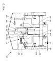
- the device 101 shown in Figure 3 corresponds to the device designated in Figures 1 and 2 with 11 and is integrated in the transport system of the filling station 1 or 1 'to the mouthpieces 105 filled hollow glass container 104, 104', on which by dripping filler to be able to deposit residues by foaming or spilling over, to be able to clean.
- the device 101 is in this case arranged on a frame which carries a transport means 103 in the form of a conveyor belt for transporting the hollow glass containers 104, 104 ' and consists of a steam jet cleaning unit 111, which has a number of nozzles 112, 112 '... and 113, 113; ... arranged laterally next to the transport means 103.
- a main line 114 in which a shut-off valve 117 is inserted, and supply lines 115 and 116, the nozzles 112, 112 '... and 113, 113' ... are fed saturated steam at a temperature of approx. 120 ° C, the the hollow glass container 104 is blasted onto the mouthpieces 105.
- the nozzles 112, 112 '. . . and 113, 113 '... are pivotable both vertically and perpendicular to the hollow glass containers 104, 104' and in the direction of their conveyance, so that the device 101 can be converted in a short time and thus adapted to the size of the items to be cleaned Hollow glass container 104 or 104 'is to be made.
- the expediently designed as flat jet nozzles 112, 112 '... are arranged offset with respect to the nozzles 113, 113' ... of the opposite row, as can be seen in FIG affect. Due to pressure reducing valves 118 and 119 installed in the supply lines 116 and 117, it is also possible that the water vapor supplied to the nozzles 112, 112 ′ ... has a different pressure level than the water vapor flowing into the nozzles 113, 113 ′ ... so that even with directly opposite nozzles 112, 112 '..., 113, 113' ... whose jet areas are adjustable and adaptable to each other.
- the steam jet cleaning unit 111 is almost completely surrounded by a housing 121 supported on a holder 124, in the end walls of which for carrying the means of transport 103 and for introducing the housing cleaning hollow glass container 104, 104 'cutouts 122 are incorporated.
- the housing 121 is equipped with water drainage channels 123 for collecting condensed water.
- a steam jet 120 can be directed onto the mouth 106 of the hollow glass container 104, so that water vapor reaches the unfilled part of the hollow glass container 104. Is immediately afterwards, ie as long as there is still water vapor in the area of the mouth 106, the hollow glass container 104 by a z. B. sealed by induction foil 107, so if the closure is tight, a slight negative pressure is formed in the hollow glass container 104, through which the foil 107, as shown in FIG. 5, is drawn inwards. The tightness of the closure can thus be checked by visual inspection without difficulty.
Landscapes
- Engineering & Computer Science (AREA)
- Mechanical Engineering (AREA)
- Filling Of Jars Or Cans And Processes For Cleaning And Sealing Jars (AREA)
Applications Claiming Priority (4)
| Application Number | Priority Date | Filing Date | Title |
|---|---|---|---|
| DE8813843U | 1988-11-05 | ||
| DE8813838U | 1988-11-05 | ||
| DE8813843U DE8813843U1 (de) | 1988-11-05 | 1988-11-05 | Reinigungsaggregat für Hohlglasbehälter |
| DE8813838U DE8813838U1 (de) | 1988-11-05 | 1988-11-05 | Abfüll-Station |
Publications (1)
| Publication Number | Publication Date |
|---|---|
| EP0368058A1 true EP0368058A1 (fr) | 1990-05-16 |
Family
ID=25953736
Family Applications (1)
| Application Number | Title | Priority Date | Filing Date |
|---|---|---|---|
| EP89119470A Withdrawn EP0368058A1 (fr) | 1988-11-05 | 1989-10-20 | Poste de remplissage |
Country Status (1)
| Country | Link |
|---|---|
| EP (1) | EP0368058A1 (fr) |
Cited By (3)
| Publication number | Priority date | Publication date | Assignee | Title |
|---|---|---|---|---|
| WO1995001911A1 (fr) * | 1993-07-08 | 1995-01-19 | Gessel Juergen | Dispositif pour le remplissage de recipients refermables, tels que bouteilles, verres ou similaires, avec des produits liquides, pateux ou coulants |
| ES2147091A1 (es) * | 1997-08-08 | 2000-08-16 | Becerro Martin Vicente | Nueva llenadora de envases con preparados alimenticios diversos. |
| CN103771322A (zh) * | 2012-10-23 | 2014-05-07 | 江苏博得龙电动工具有限公司 | 一种糖浆、膏剂洗烘灌一体机 |
Citations (6)
| Publication number | Priority date | Publication date | Assignee | Title |
|---|---|---|---|---|
| BE390116A (fr) * | ||||
| US1714075A (en) * | 1925-11-23 | 1929-05-21 | Closure Service Company | Means for cleaning bottles or other containers |
| US3097658A (en) * | 1961-02-27 | 1963-07-16 | Auchor Hocking Glass Corp | Rotary jar washer |
| US3180068A (en) * | 1962-04-12 | 1965-04-27 | Anchor Hocking Glass Corp | Washing and sealing machine |
| USRE25962E (en) * | 1966-02-22 | Container closing machinery | ||
| DE3517074A1 (de) * | 1985-05-11 | 1986-11-13 | Seitz Enzinger Noll Maschinenbau Ag, 6800 Mannheim | Abfuellanlage |
-
1989
- 1989-10-20 EP EP89119470A patent/EP0368058A1/fr not_active Withdrawn
Patent Citations (6)
| Publication number | Priority date | Publication date | Assignee | Title |
|---|---|---|---|---|
| BE390116A (fr) * | ||||
| USRE25962E (en) * | 1966-02-22 | Container closing machinery | ||
| US1714075A (en) * | 1925-11-23 | 1929-05-21 | Closure Service Company | Means for cleaning bottles or other containers |
| US3097658A (en) * | 1961-02-27 | 1963-07-16 | Auchor Hocking Glass Corp | Rotary jar washer |
| US3180068A (en) * | 1962-04-12 | 1965-04-27 | Anchor Hocking Glass Corp | Washing and sealing machine |
| DE3517074A1 (de) * | 1985-05-11 | 1986-11-13 | Seitz Enzinger Noll Maschinenbau Ag, 6800 Mannheim | Abfuellanlage |
Cited By (3)
| Publication number | Priority date | Publication date | Assignee | Title |
|---|---|---|---|---|
| WO1995001911A1 (fr) * | 1993-07-08 | 1995-01-19 | Gessel Juergen | Dispositif pour le remplissage de recipients refermables, tels que bouteilles, verres ou similaires, avec des produits liquides, pateux ou coulants |
| ES2147091A1 (es) * | 1997-08-08 | 2000-08-16 | Becerro Martin Vicente | Nueva llenadora de envases con preparados alimenticios diversos. |
| CN103771322A (zh) * | 2012-10-23 | 2014-05-07 | 江苏博得龙电动工具有限公司 | 一种糖浆、膏剂洗烘灌一体机 |
Similar Documents
| Publication | Publication Date | Title |
|---|---|---|
| DE19727942C2 (de) | Maschine und Verfahren zum Verschließen von Flaschen mit Verschlußkappen | |
| DE19716846C1 (de) | Evakuier- und Verschließvorrichtung | |
| DE69311321T2 (de) | Vorrichtung und verfahren zum befüllen von behältern | |
| DE102008032123A1 (de) | Vorrichtung zum Transportieren von Behältnissen mit Kühlung für die Behältnisse | |
| EP0611695A1 (fr) | Procédé et dispositif pour remplir et fermer un récipient à deux compartiments en matière plastique | |
| DE2647912A1 (de) | Vorrichtung zur reinigung von behaeltern, insbesondere flaschen | |
| DE2509611A1 (de) | Vorrichtung zum sterilen verpacken von guetern in behaelter | |
| DE2251455A1 (de) | Verfahren und vorrichtung zum behandeln von artikeln mit einem sterilisierungsmedium | |
| DE3215436C2 (de) | Vorrichtung zum Herstellen einer Packung | |
| EP0368058A1 (fr) | Poste de remplissage | |
| DE3605640C2 (fr) | ||
| DE3713571A1 (de) | Anlage zum fuellen und verschliessen von oben offenen saecken | |
| DE4037254C2 (fr) | ||
| EP0278322A2 (fr) | Dispositif de revêtement par pulvérisation de goulots de récipients | |
| DE2719957B2 (de) | Etikettiervorrichtung | |
| DE8813838U1 (de) | Abfüll-Station | |
| DE4024331A1 (de) | Vorrichtung zum sortieren, verteilen und transportieren von verpackungseinheiten, insbesondere kunststoffflaschen, kaesten und kartons | |
| DE8813843U1 (de) | Reinigungsaggregat für Hohlglasbehälter | |
| EP0978451B1 (fr) | Machine d'emballage pour produits alimentaires | |
| DE527588C (de) | Selbsttaetige Resteentleerungs- und Vorspritzvorrichtung fuer Hohlgefaesse | |
| DE60304190T2 (de) | Konditioniereinrichtung für ausgabekopf in einer färbemittelausgabemaschine | |
| DE696851C (de) | Maschine zum Etikettieren von aufrecht stehend vorbewegten Flaschen o. dgl. | |
| CH657586A5 (en) | Apparatus for racking powdery, granular, pasty or liquid materials into containers | |
| DE68905304T2 (de) | Verfahren zum drucken von rechteckige gegenstaenden und siebdruckmaschine, geeignet fuer das drucken. | |
| DE2515993B2 (de) | Glaswaschmaschine |
Legal Events
| Date | Code | Title | Description |
|---|---|---|---|
| PUAI | Public reference made under article 153(3) epc to a published international application that has entered the european phase |
Free format text: ORIGINAL CODE: 0009012 |
|
| AK | Designated contracting states |
Kind code of ref document: A1 Designated state(s): AT BE CH DE ES FR GB GR IT LI NL SE |
|
| STAA | Information on the status of an ep patent application or granted ep patent |
Free format text: STATUS: THE APPLICATION IS DEEMED TO BE WITHDRAWN |
|
| 18D | Application deemed to be withdrawn |
Effective date: 19901119 |