EP0368128A2 - Circuit pour capteur inductif - Google Patents
Circuit pour capteur inductif Download PDFInfo
- Publication number
- EP0368128A2 EP0368128A2 EP19890120230 EP89120230A EP0368128A2 EP 0368128 A2 EP0368128 A2 EP 0368128A2 EP 19890120230 EP19890120230 EP 19890120230 EP 89120230 A EP89120230 A EP 89120230A EP 0368128 A2 EP0368128 A2 EP 0368128A2
- Authority
- EP
- European Patent Office
- Prior art keywords
- comparator
- circuit
- inductance
- output
- sensor
- Prior art date
- Legal status (The legal status is an assumption and is not a legal conclusion. Google has not performed a legal analysis and makes no representation as to the accuracy of the status listed.)
- Withdrawn
Links
- 230000001939 inductive effect Effects 0.000 title claims abstract description 12
- 238000011156 evaluation Methods 0.000 claims description 10
- 238000005259 measurement Methods 0.000 description 9
- 230000010355 oscillation Effects 0.000 description 8
- 238000010586 diagram Methods 0.000 description 6
- 239000003990 capacitor Substances 0.000 description 4
- 230000003071 parasitic effect Effects 0.000 description 4
- 230000001133 acceleration Effects 0.000 description 1
- 230000002411 adverse Effects 0.000 description 1
- 230000001419 dependent effect Effects 0.000 description 1
- 238000006073 displacement reaction Methods 0.000 description 1
- 230000000694 effects Effects 0.000 description 1
- 238000005516 engineering process Methods 0.000 description 1
- 230000005284 excitation Effects 0.000 description 1
- 239000000463 material Substances 0.000 description 1
- 238000005070 sampling Methods 0.000 description 1
- 239000013589 supplement Substances 0.000 description 1
- 238000004804 winding Methods 0.000 description 1
Images


Classifications
-
- G—PHYSICS
- G01—MEASURING; TESTING
- G01D—MEASURING NOT SPECIALLY ADAPTED FOR A SPECIFIC VARIABLE; ARRANGEMENTS FOR MEASURING TWO OR MORE VARIABLES NOT COVERED IN A SINGLE OTHER SUBCLASS; TARIFF METERING APPARATUS; MEASURING OR TESTING NOT OTHERWISE PROVIDED FOR
- G01D5/00—Mechanical means for transferring the output of a sensing member; Means for converting the output of a sensing member to another variable where the form or nature of the sensing member does not constrain the means for converting; Transducers not specially adapted for a specific variable
- G01D5/12—Mechanical means for transferring the output of a sensing member; Means for converting the output of a sensing member to another variable where the form or nature of the sensing member does not constrain the means for converting; Transducers not specially adapted for a specific variable using electric or magnetic means
- G01D5/14—Mechanical means for transferring the output of a sensing member; Means for converting the output of a sensing member to another variable where the form or nature of the sensing member does not constrain the means for converting; Transducers not specially adapted for a specific variable using electric or magnetic means influencing the magnitude of a current or voltage
- G01D5/20—Mechanical means for transferring the output of a sensing member; Means for converting the output of a sensing member to another variable where the form or nature of the sensing member does not constrain the means for converting; Transducers not specially adapted for a specific variable using electric or magnetic means influencing the magnitude of a current or voltage by varying inductance, e.g. by a movable armature
- G01D5/2006—Mechanical means for transferring the output of a sensing member; Means for converting the output of a sensing member to another variable where the form or nature of the sensing member does not constrain the means for converting; Transducers not specially adapted for a specific variable using electric or magnetic means influencing the magnitude of a current or voltage by varying inductance, e.g. by a movable armature by influencing the self-induction of one or more coils
-
- G—PHYSICS
- G01—MEASURING; TESTING
- G01R—MEASURING ELECTRIC VARIABLES; MEASURING MAGNETIC VARIABLES
- G01R27/00—Arrangements for measuring resistance, reactance, impedance, or electric characteristics derived therefrom
- G01R27/02—Measuring real or complex resistance, reactance, impedance, or other two-pole characteristics derived therefrom, e.g. time constant
- G01R27/26—Measuring inductance or capacitance; Measuring quality factor, e.g. by using the resonance method; Measuring loss factor; Measuring dielectric constants ; Measuring impedance or related variables
- G01R27/2611—Measuring inductance
Definitions
- the invention relates to an oscillator circuit for evaluating inductive sensors, in particular using microprocessors.
- Electronic circuits are increasingly used for control and regulation tasks, for example in motor vehicles.
- Sensor technology is of particular importance as a link between electronics and physical parameters.
- Inductive components that work without contact and are therefore very reliable and reliable are preferably used. Due to their different shapes, they are suitable for recording the various physical parameters such as speed, angle, acceleration, level, flow rate, position or path difference.
- the actual measurement problem is to determine the inductance L of a coil, which is a measure of the physical quantity of interest.
- the principle of passive networks is known from EP 0 207 218 A2 and EP 0 126 846 A2.
- the processor stimulates a network that contains an inductive displacement sensor as a frequency-determining element with a step function.
- the processor shows the processor that a predetermined value has been reached.
- the time difference between step excitation and reaching the switching threshold represents information about the size of the measuring coil.
- the principle of the oscillator circuit is known from DE-OS 29 24 092 and DE-S 20 46 336.
- An inductive Position sensor used in the feedback branch of an amplifier stage, which is thereby excited to vibrate. Both analog stages with transistors or operational amplifiers and digital stages with inverters or comparators can be used.
- the oscillation frequency is determined by the processor by either measuring the period of an oscillation or the number of oscillations during a gate time.
- the required time or frequency measurement is carried out by the processor.
- the processor In the first-mentioned principle, the processor is also required to generate the step function to excite the passive network.
- a disadvantage of the aforementioned circuit principles is the high outlay on components and the negative influence of the series resistance. This series resistance must be temperature-compensated in the known circuits, since only then can a high measuring accuracy be achieved over a wide temperature range.
- the measured values obtained with known circuits are adversely affected by parasitic capacitances, such as those which occur in lines, for example, in motor vehicles.
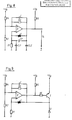
- FIG. 1 shows the electrical equivalent circuit diagram of an inductive sensor with a variable inductance, the typical size of which is around 10 mH.
- the series resistance R S is also shown to be variable, since the conductivity of the winding material and the eddy current losses are not constant.
- Parallel to the series connection of L and R S the capacitor Cp characterizing the capacitance of the turns is shown.
- a comparator with an open collector output will be available in the majority of applications. Then the pull-up resistor R5 between the comparator output and U B is connected. This is shown in Figure 3. There is also shown a capacitor C parallel to R3.
- FIG. 5 shows the oscillation frequency as a function of the sensor inductance for an exemplary dimensioning.
- a characteristic curve is predefined for an evaluation processor, from which it determines the inductance values at certain frequencies.
- a model with an open collector output was used for the comparator, which takes into account a current-independent value U A (min) for the saturation voltage of the output transistor.
- U A (min) for the saturation voltage of the output transistor.
- the curves shown apply on the condition that R1 is dimensioned much larger than R S and the influence of the series resistance R S can be neglected. This dimensioning results in time constants for the signals which, when measured directly by the processor, will lead to unlawfully high measurement errors.
- the finite comparator properties such as the current-dependent saturation output voltage and the finite no-load gain, must be taken into account, as well as the exact data of the measurement sensor.
- the measurement results shown in FIGS. 6 and 7 show the influence of the operating voltage and the series resistance on the period R. The measurement results shown here show the great agreement with the theoretically expected values.
- the parasitic capacitance CL2 is to be assessed more critically, since it acts in parallel with the resistor R1 which is high-resistance compared to R S and its influence cannot be reduced by simple circuit variation. In order not to exceed predetermined error bounds due to the effects of the line capacity at this point, the opponent stood R1 be dimensioned accordingly.
Landscapes
- Physics & Mathematics (AREA)
- General Physics & Mathematics (AREA)
- Electronic Switches (AREA)
- Measurement Of Resistance Or Impedance (AREA)
Applications Claiming Priority (2)
| Application Number | Priority Date | Filing Date | Title |
|---|---|---|---|
| DE3837114 | 1988-11-02 | ||
| DE3837114 | 1988-11-02 |
Publications (2)
| Publication Number | Publication Date |
|---|---|
| EP0368128A2 true EP0368128A2 (fr) | 1990-05-16 |
| EP0368128A3 EP0368128A3 (fr) | 1991-07-03 |
Family
ID=6366280
Family Applications (1)
| Application Number | Title | Priority Date | Filing Date |
|---|---|---|---|
| EP19890120230 Withdrawn EP0368128A3 (fr) | 1988-11-02 | 1989-11-01 | Circuit pour capteur inductif |
Country Status (1)
| Country | Link |
|---|---|
| EP (1) | EP0368128A3 (fr) |
Cited By (3)
| Publication number | Priority date | Publication date | Assignee | Title |
|---|---|---|---|---|
| JP2018526649A (ja) * | 2015-08-28 | 2018-09-13 | ローベルト ボツシユ ゲゼルシヤフト ミツト ベシユレンクテル ハフツングRobert Bosch Gmbh | センサコイルインダクタンスを求めるための方法及び装置 |
| CN113835046A (zh) * | 2021-08-05 | 2021-12-24 | 延边大学 | 一种基于企业使用环境下的电感特性参数检测仪 |
| DE102023122174A1 (de) | 2023-08-18 | 2025-02-20 | Huf Hülsbeck & Fürst Gmbh & Co. Kg | Vorrichtung zum Erfassen von Betätigungssignalen |
Family Cites Families (3)
| Publication number | Priority date | Publication date | Assignee | Title |
|---|---|---|---|---|
| DE2046336A1 (de) * | 1970-09-19 | 1972-04-27 | Daimler Benz Ag | Elektronischer Weggeber |
| GB2062237A (en) * | 1979-09-26 | 1981-05-20 | Electronic Lab Ltd | Conversion of a linear displacement to a time-dependent signal |
| DE2939665A1 (de) * | 1979-09-29 | 1981-04-16 | Robert Bosch Gmbh, 7000 Stuttgart | Auswerteschaltung fuer einen halbdifferential-kurzschluss-geber |
-
1989
- 1989-11-01 EP EP19890120230 patent/EP0368128A3/fr not_active Withdrawn
Cited By (4)
| Publication number | Priority date | Publication date | Assignee | Title |
|---|---|---|---|---|
| JP2018526649A (ja) * | 2015-08-28 | 2018-09-13 | ローベルト ボツシユ ゲゼルシヤフト ミツト ベシユレンクテル ハフツングRobert Bosch Gmbh | センサコイルインダクタンスを求めるための方法及び装置 |
| CN113835046A (zh) * | 2021-08-05 | 2021-12-24 | 延边大学 | 一种基于企业使用环境下的电感特性参数检测仪 |
| DE102023122174A1 (de) | 2023-08-18 | 2025-02-20 | Huf Hülsbeck & Fürst Gmbh & Co. Kg | Vorrichtung zum Erfassen von Betätigungssignalen |
| WO2025040445A1 (fr) | 2023-08-18 | 2025-02-27 | Huf Hülsbeck & Fürst Gmbh & Co. Kg | Dispositif de détection de signaux de fonctionnement |
Also Published As
| Publication number | Publication date |
|---|---|
| EP0368128A3 (fr) | 1991-07-03 |
Similar Documents
| Publication | Publication Date | Title |
|---|---|---|
| DE10156027B4 (de) | Abgleichbare Filterschaltung | |
| EP3335012B1 (fr) | Unité de commande electronique | |
| DE3835090C2 (fr) | ||
| EP0126846B1 (fr) | Capteur inductif | |
| DE68926296T2 (de) | Rückmelde-übertragevorrichtung mit ausgeglichener last | |
| EP1419365B1 (fr) | Dispositif et procede de lecture d'un condensateur differentiel comportant un premier et un deuxieme condensateur partiel | |
| EP0766398A1 (fr) | Commutateur capacitif | |
| DE3713821A1 (de) | Trennverstaerker mit genauer zeitlage der ueber die isolationsbarriere gekoppelten signale | |
| DE3343885A1 (de) | Induktiver sensor | |
| EP0438634A2 (fr) | Circuit d'évaluation pour capteur capacitif | |
| DE102018109916A1 (de) | EMV robuste mikroelektronisch integrierbare Messschaltung für Kapazitätswerte einer unbekannten Kapazität | |
| DE102015216479A1 (de) | Verfahren und Vorrichtung zum Bestimmen einer Sensorspuleninduktivität | |
| EP0358122B1 (fr) | Capteur de températures | |
| EP0280261A2 (fr) | Circuit pour la production d'un signal carré indépendant de la température à une grandeur mesurée | |
| EP0561054B1 (fr) | Appareil et procédé pour mesurer la constante de temps d'un capteur de déplacement | |
| DE2702815C3 (de) | Temperaturmeßvorrichtung | |
| EP0343403B1 (fr) | Circuit pour l'auto-excitation d'un oscillateur mécanique jusqu'à sa fréquence de résonance propre | |
| DE10102791A1 (de) | Elektrischer Messumformer | |
| DE3919191C2 (de) | Auswerteschaltung | |
| DE2106916C3 (de) | Induktiver Meßumformer zur Umformung einer mechanischen Auslenkung in eine dazu proportionale elektrische Größe | |
| DE102008042765A1 (de) | Vorrichtung und Verfahren zum Messen eines Widerstandswerts | |
| DE1284110B (de) | Kapazitaets-Pegelschaltanordnung | |
| DE102004003112B4 (de) | Vorrichtung und Verfahren zur kapazitiven Messwerterfassung | |
| DE4222346C2 (de) | Einrichtung zur Erhöhung der Störsicherheit bei der Differentiation von Signalen | |
| DE3702169C2 (fr) |
Legal Events
| Date | Code | Title | Description |
|---|---|---|---|
| PUAI | Public reference made under article 153(3) epc to a published international application that has entered the european phase |
Free format text: ORIGINAL CODE: 0009012 |
|
| AK | Designated contracting states |
Kind code of ref document: A2 Designated state(s): DE ES FR GB IT SE |
|
| PUAL | Search report despatched |
Free format text: ORIGINAL CODE: 0009013 |
|
| AK | Designated contracting states |
Kind code of ref document: A3 Designated state(s): DE ES FR GB IT SE |
|
| RHK1 | Main classification (correction) |
Ipc: G01D 5/20 |
|
| RIN1 | Information on inventor provided before grant (corrected) |
Inventor name: BUTSCHER, KARL-HEINZ Inventor name: LEIBER, HEINZ, DIPL.-ING. Inventor name: ADOMAT, ROLF, DIPL.-ING. Inventor name: BURGHOFF, HEINZ-GEORG, DR. DIPL.-PHYS. Inventor name: HASEL, OSKAR Inventor name: ULKE, WALTER, DIPL.-ING. |
|
| STAA | Information on the status of an ep patent application or granted ep patent |
Free format text: STATUS: THE APPLICATION IS DEEMED TO BE WITHDRAWN |
|
| 18D | Application deemed to be withdrawn |
Effective date: 19920104 |