EP0368249A2 - Sectionneur - Google Patents
Sectionneur Download PDFInfo
- Publication number
- EP0368249A2 EP0368249A2 EP89120615A EP89120615A EP0368249A2 EP 0368249 A2 EP0368249 A2 EP 0368249A2 EP 89120615 A EP89120615 A EP 89120615A EP 89120615 A EP89120615 A EP 89120615A EP 0368249 A2 EP0368249 A2 EP 0368249A2
- Authority
- EP
- European Patent Office
- Prior art keywords
- switch
- contact
- electrode shield
- resistor
- disconnecting switch
- Prior art date
- Legal status (The legal status is an assumption and is not a legal conclusion. Google has not performed a legal analysis and makes no representation as to the accuracy of the status listed.)
- Granted
Links
Images




Classifications
-
- H—ELECTRICITY
- H01—ELECTRIC ELEMENTS
- H01H—ELECTRIC SWITCHES; RELAYS; SELECTORS; EMERGENCY PROTECTIVE DEVICES
- H01H31/00—Air-break switches for high tension without arc-extinguishing or arc-preventing means
- H01H31/26—Air-break switches for high tension without arc-extinguishing or arc-preventing means with movable contact that remains electrically connected to one line in open position of switch
- H01H31/32—Air-break switches for high tension without arc-extinguishing or arc-preventing means with movable contact that remains electrically connected to one line in open position of switch with rectilinearly-movable contact
-
- H—ELECTRICITY
- H01—ELECTRIC ELEMENTS
- H01H—ELECTRIC SWITCHES; RELAYS; SELECTORS; EMERGENCY PROTECTIVE DEVICES
- H01H33/00—High-tension or heavy-current switches with arc-extinguishing or arc-preventing means
- H01H33/02—Details
- H01H33/04—Means for extinguishing or preventing arc between current-carrying parts
- H01H33/16—Impedances connected with contacts
Definitions
- the present invention relates generally to a disconnecting switch for switching a bus bar or a line by breaking current therein in a power station or a transforming station.
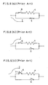
- FIGs. 6(a), 6(b) and 6(c) are equivalent circuits corresponding FIGs. 5(a), 5(b) and 5(c), respectively.
- the interrupting part consists of a main contact 2, an arc contact 3 and a movable contact 1.
- the arc contact 3 is set protruding beyond the main contact 2 toward the movable contact 1.
- FIGs. 6(a), 6(b) and 6(c) Resistance owing to material having a relatively high resistance of the arc contact 3 is shown in FIGs. 6(a), 6(b) and 6(c) as an equivalent resistor 4.
- a switch 5 consists of the movable contact 1 and the main contact 2
- a switch 6 consists of the movable contact 1 and the arc contact 3.
- Arcs are generated at contact-parting in switches 5 and 6.
- FIGs. 5(a) and 6(a) show closed state of the disconnecting switch. Both the switches 5 and 6 are closed, wherein the movable contact 1 and the main contact 2 make a perfect touch and connection. In this case, current flow I is shown by an arrow. Next, the movable contact I is moved parting from the main contact 2, but is still touching with the arc contact 3 as shown in FIGs. 5(b) and 6(b); namely only the switch 5 is open, but the switch 6 is still closed. In this case current I flows in the switch 6 through the resistor 4. Then, the movable contact 1 is moved more parting from the arc contact 3 as shown in FIGs.
- the object of the present invention is to solve the above-mentioned problems and obtain a disconnecting switch having an improved interruption characteristic based on its sufficient current limiting action with compact size.
- the disconnecting switch in accordance with the present invention comprises: a container, a fixed electrode shield mounted in the container being insulated therefrom, a moving electrode shield mounted in the container being insulated therefrom, and from the fixed electrode shield, a movable contact having a rod-shaped sliding part, held slidably along the axis thereof in the moving electrode shield and electrically connected to the moving electrode shield, a main contact which is supported in the fixed electrode shield and electrically connected thereto, and is to contact the rod-shaped sliding part by sliding motion of the movable contact, a resistor supported in the fixed electrode shield, with its one end electrically connected with the fixed electrode shield, and an arc contact which is held movable in the fixed electrode shield and has a rear end electrically connected slidably to the other end of the resistor and a front end for touching the rod-shaped sliding part.
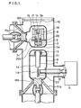
- FIG.1 is a vertical sectional view of a disconnecting switch of the present invention.
- a fixed electrode shield 8 (which is receiving a fixed contact namely a main contact 2) having a connection part (connector) 18a is held by an insulator 17a, which is supported in a container 10 by periphery thereof.
- a moving electrode shield 9 (which is receiving a movable contact 1) having a connection part (connector) 18b is held by an insulator 17b, which is supported in the container 10 by periphery thereof.
- a supporting conductor 20 for supporting an arc contact 3, the main contact 2 and resistors 16 etc., is attached therein.
- the arc contact 3 is composed of top end 3a, central flange portion 3c, and tail end 3b.
- a compression spring 15 is mounted between a connecting conductor plate 21 and the central flange portion 3c.
- the central flange portion 3c is pressed against an insulator 20a fixed to the supporting conductor 20 by resilient force of the spring 15.
- the arc contact 3 is slidably held in a through-hole of the insulator 20a.
- the arc contact 3 is insulated by the insulator 20a, and hence never electrically connected with the supporting conductor 20 directly.
- the arc contact 3 is slid upward, sliding through the through-hole of the insulator 20a.
- the tail end 3b of the arc contact 3 is inserted into a sliding conductor 14 whereby the arc contact 3 is electrically connected with the sliding conductor 14 while sliding upward and downward.
- the sliding conductor 22 is attached on the connecting conductor plate 21.
- a pile of several ring-shaped resistors 16, which are made of carbon resistor or the like is mounted between the connecting conductor plate 21 and the supporting conductor 20.
- the main contact 2 is fixed to the supporting conductor 20.
- the moving electrode shield 9 there are a supporting conductor 21, which is electrically connected thereto, and a movable contact 1.
- the movable contact 1 consists of cylindrical part 1a and a plate part 1b.
- the plate part 1b is connected with a crank cam 22, which is to be driven by an insulator rod 12.
- Side surface of upper part of the cylindrical part 1a slides in a throughholes of the supporting conductor 21 and a sliding conductor 13.
- a drive mechanism 11 drives the crank cam 22 by rotating the insulator rod 12.
- the insulator rod insulates the movable contact 1 of high potential from the driver 11, which is of grounded potential.
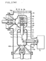
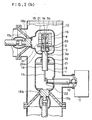
- FIGs. 2(a), 2(b) and 2(c) are vertical sectional views in various stages of breaking process of the disconnecting switch.
- FIG.2(a) wherein a closed state of the disconnecting switch is shown, the movable contact 1 contacts both the main contact 2 and the top end 3a. A current flows mainly through the movable contact 1 and the main contact 2.
- the movable contact 1 is moved downward by the driver 11, and the movable contact 1 parts from the main contact 2 as shown in FIG.2(b), but the top end face of the movable contact 1 is still in contact with the arc contact 3.
- the current flows through movable contact 1, the arc contact 3, the sliding conductor 14, the connecting conductor plate 21, the resistors 16 and the supporting conductor 20, to the fixed electrode shield 8, in this order.
- This current is sufficiently limited by the current limiting action by the resistors 16.
- the movable contact moves further downward, and finally the top end face of the movable contact 1 parts from the arc contact 3 as shown in FIG.2(c), and the resistor-limited current is interrupted.
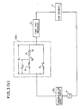
- FIGs. 3(a), 3(b) and 3(c) are single-line equivalent circuit diagrams of the disconnecting switch shown in FIGs. 2(a), 2(b) and 2(c), respectively.
- mark P designates a power source
- mark Z0 represents impedance of the power source
- mark Z1 represents a feed loop impedance
- mark Z designates a load impedance
- Mark I designates the whole current, namely the load current.
- a disconnecting switch DS1 which represents the disconnecting switch of FIG. 1, breaks the load current I.
- Mark I R designates a current portion flowing through a switch 6, which is formed by the movable contact 1 and the arc contact 3 (of FIG.2), and the resistors 16 in series therewith.
- Mark I M designates a current portion flowing through a switch 5, which is formed by the movable contact 1 and the main contact 2.
- the state of the disconnecting switch DS1 shown in FIG.2(a) changes to that of FIG.2(b).
- the movable contact 1 is apart from the main contact 2, namely the switch 5 is opened. But the movable contact 1 is still in contact with the arc contact 3, namely the switch 6 is still closed (FIG.3(b)).
- the opening of the switch 5 the current I M in the switch 5 is interrupted, and the current I M transfer to the branch of the switch 6.
- the time period from opening of the switch 5 to the complete transfer of the current I M to the branch of the switch 6 depends on the inherent interrupting characteristics of the switch 5 and the ratio of resistance R of the resistors 16 to the impedance Z1.
- the current 1 M is interrupted, and a current I R ′ in the branch of the switch 6 and the resistors 16 (which is designated as I R ′ and is larger than I R ) flows, as shown in FIG.3(b).
- the current I R ′ is dependent on a combined impedance Z1′, which is a combination of impedance Z1 and R.
- the easy interruption of the disconnector of the present invention owes to short arcing period or no arcing.
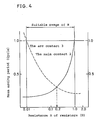
- the relation between resistance R of resistors 16 and mean arcing period of the main contact 2, and the relation between resistance R of resistors 16 and mean arcing period of the arc contact 3 (switch 6 of FIGs. 3(a), 3(b) and 3(c)) in a disconnecting switch, obtained by experiments is shown in FIG.4.
- the example disconnector is operated for loop current of 8000 A, recovery voltage of 300 V.
- a requirement for a disconnecting switch is an interruption characteristic for enabling about 200 time successive interruption of loop current without maintenance or checking.
- the value of R is to be selected about 0.2 ⁇ in this example. This value of 0.2 ⁇ is about 5 times as large as the loop impedance of a longest loop.
Landscapes
- Arc-Extinguishing Devices That Are Switches (AREA)
- Keying Circuit Devices (AREA)
Applications Claiming Priority (2)
| Application Number | Priority Date | Filing Date | Title |
|---|---|---|---|
| JP14609988 | 1988-11-08 | ||
| JP146099/88U | 1988-11-08 |
Publications (3)
| Publication Number | Publication Date |
|---|---|
| EP0368249A2 true EP0368249A2 (fr) | 1990-05-16 |
| EP0368249A3 EP0368249A3 (fr) | 1991-07-03 |
| EP0368249B1 EP0368249B1 (fr) | 1994-09-07 |
Family
ID=15400122
Family Applications (1)
| Application Number | Title | Priority Date | Filing Date |
|---|---|---|---|
| EP89120615A Expired - Lifetime EP0368249B1 (fr) | 1988-11-08 | 1989-11-07 | Sectionneur |
Country Status (5)
| Country | Link |
|---|---|
| US (1) | US5091614A (fr) |
| EP (1) | EP0368249B1 (fr) |
| JP (1) | JPH0719504B2 (fr) |
| CN (1) | CN1021093C (fr) |
| DE (1) | DE68918047T2 (fr) |
Cited By (3)
| Publication number | Priority date | Publication date | Assignee | Title |
|---|---|---|---|---|
| EP0444568A1 (fr) * | 1990-02-27 | 1991-09-04 | Gec Alsthom Sa | Disjoncteur à coupure assistée par varistance |
| AT397003B (de) * | 1992-01-16 | 1994-01-25 | Holly Rudolf | Einrichtung zum abschalten eines hochspannungsstromkreises |
| EP3850724A1 (fr) * | 2018-09-11 | 2021-07-21 | C.R.D. Centro Ricerche Ducati Trento S.r.l. | Système d'énergie de secours basse tension, en particulier pour signalisation ferroviaire |
Families Citing this family (10)
| Publication number | Priority date | Publication date | Assignee | Title |
|---|---|---|---|---|
| JP2679499B2 (ja) * | 1991-12-27 | 1997-11-19 | 三菱電機株式会社 | 遮断器及び開閉部の操作機構 |
| US5291068A (en) * | 1992-09-01 | 1994-03-01 | Sterner Lighting Systems Incorporated | Touch sensitive switching apparatus |
| JP3082591B2 (ja) * | 1994-09-29 | 2000-08-28 | 株式会社日立製作所 | 遮断器 |
| AT410867B (de) * | 2001-04-06 | 2003-08-25 | Siemens Ag Oesterreich | Spannungsversorgung mit abschaltsicherung |
| FR2896335B1 (fr) * | 2006-01-17 | 2008-11-14 | Areva T & D Sa | Disjoncteur de generateur avec resistance inseree |
| EP2309526B1 (fr) * | 2009-10-08 | 2012-10-03 | ABB Technology AG | Commutateur de puissance avec des branches de courant nominal parallèles |
| FR2985081B1 (fr) | 2011-12-21 | 2015-03-06 | Alstom Technology Ltd | Dispositif de protection contre les particules engendrees par un arc electrique de commutation |
| FR2996352B1 (fr) | 2012-10-02 | 2014-10-31 | Alstom Technology Ltd | Dispositif de contact electrique de type doigt de contact a fort courant nominal |
| CN104269315B (zh) * | 2014-09-05 | 2016-09-14 | 中国西电电气股份有限公司 | 带限流器的大功率开关 |
| US10566155B2 (en) * | 2016-04-06 | 2020-02-18 | Mitsubishi Electric Corporation | Switch |
Family Cites Families (8)
| Publication number | Priority date | Publication date | Assignee | Title |
|---|---|---|---|---|
| US2401963A (en) * | 1943-05-07 | 1946-06-11 | Gen Electric | Electric circuit breaker |
| DE868020C (de) * | 1950-04-28 | 1953-02-23 | Sachsenwerk Licht & Kraft Ag | Fluessigkeitsarmer Loeschkammerschalter mit Vorwiderstand |
| US3912974A (en) * | 1970-02-18 | 1975-10-14 | George Leslie Hill | Circuit breaker |
| US4069406A (en) * | 1975-12-02 | 1978-01-17 | Allis-Chalmers Corporation | Closing resistor switch for gas insulated circuit breaker |
| JPS5928573B2 (ja) * | 1980-02-05 | 1984-07-13 | チッソ株式会社 | α−オレフイン重合体の製造方法 |
| GB2081976A (en) * | 1980-08-08 | 1982-02-24 | Ass Elect Ind | Arc preventing in switches |
| US4488021A (en) * | 1981-11-12 | 1984-12-11 | Mitsubishi Denki Kabushiki Kaisha | Gas insulated disconnector |
| JPS58182323A (ja) * | 1982-04-20 | 1983-10-25 | Nec Corp | 位相同期回路 |
-
1989
- 1989-04-28 JP JP1111105A patent/JPH0719504B2/ja not_active Expired - Lifetime
- 1989-11-01 CN CN89108393.6A patent/CN1021093C/zh not_active Expired - Fee Related
- 1989-11-06 US US07/431,878 patent/US5091614A/en not_active Expired - Fee Related
- 1989-11-07 DE DE68918047T patent/DE68918047T2/de not_active Expired - Fee Related
- 1989-11-07 EP EP89120615A patent/EP0368249B1/fr not_active Expired - Lifetime
Cited By (5)
| Publication number | Priority date | Publication date | Assignee | Title |
|---|---|---|---|---|
| EP0444568A1 (fr) * | 1990-02-27 | 1991-09-04 | Gec Alsthom Sa | Disjoncteur à coupure assistée par varistance |
| FR2662848A2 (fr) * | 1990-02-27 | 1991-12-06 | Alsthom Gec | Disjoncteur a coupure assistee par varistance. |
| US5170023A (en) * | 1990-02-27 | 1992-12-08 | Gec Alsthom Sa | Circuit breaker with varistor-assisted interruption |
| AT397003B (de) * | 1992-01-16 | 1994-01-25 | Holly Rudolf | Einrichtung zum abschalten eines hochspannungsstromkreises |
| EP3850724A1 (fr) * | 2018-09-11 | 2021-07-21 | C.R.D. Centro Ricerche Ducati Trento S.r.l. | Système d'énergie de secours basse tension, en particulier pour signalisation ferroviaire |
Also Published As
| Publication number | Publication date |
|---|---|
| CN1021093C (zh) | 1993-06-02 |
| CN1042621A (zh) | 1990-05-30 |
| DE68918047T2 (de) | 1995-01-05 |
| EP0368249A3 (fr) | 1991-07-03 |
| JPH02236923A (ja) | 1990-09-19 |
| JPH0719504B2 (ja) | 1995-03-06 |
| US5091614A (en) | 1992-02-25 |
| DE68918047D1 (de) | 1994-10-13 |
| EP0368249B1 (fr) | 1994-09-07 |
Similar Documents
| Publication | Publication Date | Title |
|---|---|---|
| EP0368249A2 (fr) | Sectionneur | |
| US5168139A (en) | Load-break switch having a vacuum interrupter and method of operation | |
| CA2053516A1 (fr) | Disjoncteur a basse tension et contacts multiples pour haute intensite | |
| MXPA03010405A (es) | Aparato interruptor electrico que tiene una corredera de arco con un lomo realzado. alargado. | |
| US3590186A (en) | Vacuum interrupter having series connected resistor and shunting means for the latter | |
| JPS58181218A (ja) | 複合型真空しや断器 | |
| GB1495283A (en) | Vacuum switching apparatus | |
| EP0414192B1 (fr) | Sectionneur | |
| US4419552A (en) | Circuit breaker | |
| US4539448A (en) | Disconnect switch for metal-clad, pressurized-gas insulated, high-voltage switchgear installation | |
| US2859309A (en) | Arc free multiple break circuit interrupting and isolating means | |
| US4620122A (en) | Piezoelectric contact driver for circuit interrupters | |
| JPH06508714A (ja) | 主開閉接触子と補助接触子とを備えた断路器 | |
| US3209298A (en) | Arrangement for controlling circuit conductivity | |
| US4598187A (en) | Current limiting circuit breaker | |
| US5635692A (en) | Contact arrangement for electrical apparatus | |
| CN114460450A (zh) | 一种基于高弧压技术的直流开断设备测试平台 | |
| US3750061A (en) | High-speed switch device | |
| CN2313288Y (zh) | 微型断路器的触头系统 | |
| CA1111089A (fr) | Coupe-circuit haute tension a rupture simple | |
| JPS5916232A (ja) | しや断器 | |
| JPS5916229A (ja) | 断路器 | |
| SU1343461A1 (ru) | Токоограничивающее устройство дл автоматических выключателей | |
| SU1647684A1 (ru) | Коммутационный аппарат Чурсина | |
| JPS623873Y2 (fr) |
Legal Events
| Date | Code | Title | Description |
|---|---|---|---|
| PUAI | Public reference made under article 153(3) epc to a published international application that has entered the european phase |
Free format text: ORIGINAL CODE: 0009012 |
|
| 17P | Request for examination filed |
Effective date: 19891107 |
|
| AK | Designated contracting states |
Kind code of ref document: A2 Designated state(s): CH DE FR LI |
|
| PUAL | Search report despatched |
Free format text: ORIGINAL CODE: 0009013 |
|
| AK | Designated contracting states |
Kind code of ref document: A3 Designated state(s): CH DE FR LI |
|
| 17Q | First examination report despatched |
Effective date: 19930408 |
|
| GRAA | (expected) grant |
Free format text: ORIGINAL CODE: 0009210 |
|
| AK | Designated contracting states |
Kind code of ref document: B1 Designated state(s): CH DE FR LI |
|
| REF | Corresponds to: |
Ref document number: 68918047 Country of ref document: DE Date of ref document: 19941013 |
|
| ET | Fr: translation filed | ||
| PLBE | No opposition filed within time limit |
Free format text: ORIGINAL CODE: 0009261 |
|
| STAA | Information on the status of an ep patent application or granted ep patent |
Free format text: STATUS: NO OPPOSITION FILED WITHIN TIME LIMIT |
|
| 26N | No opposition filed | ||
| REG | Reference to a national code |
Ref country code: FR Ref legal event code: D6 |
|
| PGFP | Annual fee paid to national office [announced via postgrant information from national office to epo] |
Ref country code: FR Payment date: 20011113 Year of fee payment: 13 |
|
| PGFP | Annual fee paid to national office [announced via postgrant information from national office to epo] |
Ref country code: DE Payment date: 20011119 Year of fee payment: 13 |
|
| PGFP | Annual fee paid to national office [announced via postgrant information from national office to epo] |
Ref country code: CH Payment date: 20011130 Year of fee payment: 13 |
|
| PG25 | Lapsed in a contracting state [announced via postgrant information from national office to epo] |
Ref country code: LI Free format text: LAPSE BECAUSE OF NON-PAYMENT OF DUE FEES Effective date: 20021130 Ref country code: CH Free format text: LAPSE BECAUSE OF NON-PAYMENT OF DUE FEES Effective date: 20021130 |
|
| PG25 | Lapsed in a contracting state [announced via postgrant information from national office to epo] |
Ref country code: DE Free format text: LAPSE BECAUSE OF NON-PAYMENT OF DUE FEES Effective date: 20030603 |
|
| REG | Reference to a national code |
Ref country code: CH Ref legal event code: PL |
|
| PG25 | Lapsed in a contracting state [announced via postgrant information from national office to epo] |
Ref country code: FR Free format text: LAPSE BECAUSE OF NON-PAYMENT OF DUE FEES Effective date: 20030731 |
|
| REG | Reference to a national code |
Ref country code: FR Ref legal event code: ST |