EP0368286A2 - Dispositif de centrage et de serrage pour moule métallique pour un appareil de vulcanisation de pneus - Google Patents
Dispositif de centrage et de serrage pour moule métallique pour un appareil de vulcanisation de pneus Download PDFInfo
- Publication number
- EP0368286A2 EP0368286A2 EP89120707A EP89120707A EP0368286A2 EP 0368286 A2 EP0368286 A2 EP 0368286A2 EP 89120707 A EP89120707 A EP 89120707A EP 89120707 A EP89120707 A EP 89120707A EP 0368286 A2 EP0368286 A2 EP 0368286A2
- Authority
- EP
- European Patent Office
- Prior art keywords
- metal mold
- centering
- vulcanizing machine
- centering member
- piston rod
- Prior art date
- Legal status (The legal status is an assumption and is not a legal conclusion. Google has not performed a legal analysis and makes no representation as to the accuracy of the status listed.)
- Granted
Links
Images




Classifications
-
- B—PERFORMING OPERATIONS; TRANSPORTING
- B29—WORKING OF PLASTICS; WORKING OF SUBSTANCES IN A PLASTIC STATE IN GENERAL
- B29D—PRODUCING PARTICULAR ARTICLES FROM PLASTICS OR FROM SUBSTANCES IN A PLASTIC STATE
- B29D30/00—Producing pneumatic or solid tyres or parts thereof
- B29D30/06—Pneumatic tyres or parts thereof (e.g. produced by casting, moulding, compression moulding, injection moulding, centrifugal casting)
- B29D30/08—Building tyres
- B29D30/20—Building tyres by the flat-tyre method, i.e. building on cylindrical drums
- B29D30/24—Drums
- B29D30/26—Accessories or details, e.g. membranes, transfer rings
-
- B—PERFORMING OPERATIONS; TRANSPORTING
- B29—WORKING OF PLASTICS; WORKING OF SUBSTANCES IN A PLASTIC STATE IN GENERAL
- B29D—PRODUCING PARTICULAR ARTICLES FROM PLASTICS OR FROM SUBSTANCES IN A PLASTIC STATE
- B29D30/00—Producing pneumatic or solid tyres or parts thereof
- B29D30/06—Pneumatic tyres or parts thereof (e.g. produced by casting, moulding, compression moulding, injection moulding, centrifugal casting)
- B29D30/0601—Vulcanising tyres; Vulcanising presses for tyres
- B29D30/0662—Accessories, details or auxiliary operations
-
- B—PERFORMING OPERATIONS; TRANSPORTING
- B23—MACHINE TOOLS; METAL-WORKING NOT OTHERWISE PROVIDED FOR
- B23Q—DETAILS, COMPONENTS, OR ACCESSORIES FOR MACHINE TOOLS, e.g. ARRANGEMENTS FOR COPYING OR CONTROLLING; MACHINE TOOLS IN GENERAL CHARACTERISED BY THE CONSTRUCTION OF PARTICULAR DETAILS OR COMPONENTS; COMBINATIONS OR ASSOCIATIONS OF METAL-WORKING MACHINES, NOT DIRECTED TO A PARTICULAR RESULT
- B23Q3/00—Devices holding, supporting, or positioning work or tools, of a kind normally removable from the machine
- B23Q3/18—Devices holding, supporting, or positioning work or tools, of a kind normally removable from the machine for positioning only
- B23Q3/183—Centering devices
-
- B—PERFORMING OPERATIONS; TRANSPORTING
- B29—WORKING OF PLASTICS; WORKING OF SUBSTANCES IN A PLASTIC STATE IN GENERAL
- B29C—SHAPING OR JOINING OF PLASTICS; SHAPING OF MATERIAL IN A PLASTIC STATE, NOT OTHERWISE PROVIDED FOR; AFTER-TREATMENT OF THE SHAPED PRODUCTS, e.g. REPAIRING
- B29C33/00—Moulds or cores; Details thereof or accessories therefor
- B29C33/30—Mounting, exchanging or centering
- B29C33/303—Mounting, exchanging or centering centering mould parts or halves, e.g. during mounting
-
- B—PERFORMING OPERATIONS; TRANSPORTING
- B29—WORKING OF PLASTICS; WORKING OF SUBSTANCES IN A PLASTIC STATE IN GENERAL
- B29C—SHAPING OR JOINING OF PLASTICS; SHAPING OF MATERIAL IN A PLASTIC STATE, NOT OTHERWISE PROVIDED FOR; AFTER-TREATMENT OF THE SHAPED PRODUCTS, e.g. REPAIRING
- B29C33/00—Moulds or cores; Details thereof or accessories therefor
- B29C33/30—Mounting, exchanging or centering
- B29C33/305—Mounting of moulds or mould support plates
Definitions
- the present invention relates to a device for automatically performing centering of a metal mold carried in a vulcanizing machine as well as a clamping work for a lower metal mold upon exchange of metal molds when a size and a kind of a tire to be vulcanized are changed in a tire vulcanizing machine.
- metal molds for vulcanization respectively have different configurations for respective kinds and respective sizes of tires and depending upon a tire production schedule, it is necessary to perform exchange works for metal molds fairly frequently.
- a thermal insulator 2 and a lower heat plate 3 are fixedly fastened to the frame by means of bolts 4.
- a thermal insulator 6 and an upper heat plate 7 are fixedly fastened integrally to a lower surface of a bolster plate 5 by means of bolts 8.
- the bolster plate 5 is exactly raised and lowered within a frame by means of an elevator and guide means not shown.
- Clamp rod 9 is preliminarily assembled as penetrating through holes in the bolster plate 5, the thermal insulator 6 and the upper heat plate 7.
- a clamp claw 10 At the bottom end of the clamp rod 9 is formed a clamp claw 10, and its top end is fitted to a rotating lever 13 via a key 14.
- a sprocket 11 At the middle of a shaft of the clamp rod 9 is mounted a sprocket 11 via a key 12.
- a male screw 15 is threadedly engaged with a nut 16 which is fixed to the bolster plate 5 by means of bolts 30. Bearings 17 and 18 support the clamp rod 9.
- the clamp rods 9 are assembled at four locations at equal intervals on the plane of the bolster plate 5, the respective sprockets 11 are interlocked via a roller chain 19, and thereby rotational drive for the clamp rods 9 is simultaneously transmitted to the clamp rods 9 at four locations.
- a sprocket 20 is an idler sprocket for preventing the roller chain 19 from loosening.
- Actuation of a cylinder 21 rotationally drives the clamp rod 9 via the lever 13 and the key 14.
- a clamp metal 22, a link 23, a lever 24 and a cylinder 25 are used for clamping a lower metal mold 26 and a lower heat plate 3.
- a clamp assistant plate 28 is preliminarily fastened to a top surface of an upper metal mold 27 by means of bolts 29, and thus the upper metal mold 27 and the clamp assistant plate 28 are carried into a vulcanizing machine in an integrated state.
- the bolster plate 5 When a metal mold is carried into a vulcanizing machine, at first the bolster plate 5, the thermal insulator 6 and the upper heat plate 7 are integrally raised up to the upper limit to broaden a carry-in space for the metal mold, and then, the upper and lower metal molds 26 and 27 and the clamp assistant plate 28 are made to sit at a regular position in the vulcanizing machine 3 by means of a conveying instrument such as a fork-lift or the like. Next, the bolster plate 5 is lowered to bring the upper heat plate 7 into tight contact with the clamp assistant plate 28. At this moment, the clamp claw 10 must be accommodated in the bore of the clamp assistant plate 28 at the position shown in Fig. 11. Then, by actuating the cylinder 25, the clamp metal 22 is meshed with a slot 31 in the lower metal mold 26, and thereby the lower heat plate and the slot 31 are clamped.
- the cylinder 21 is actuated to rotate the clamp rod 9, hence the clamp claw 10 is rotated by about 90° as shown in Fig. 12, and the upper heat plate 7 and the clamp assistant plate 28 are clamped.
- the clamp rod 9 rotates, the clamp rod is raised by the screw 15, and the upper heat plate 7 and the clamp assistant plate 28 are firmly held in tight contact.
- centering means for performing a centering work after the upper and lower metal molds to be exchanged have been carried into the vulcanizing machine is not provided, and a centering work for the metal mold is carried out by manual operations, so that the centering work necessitates a long period of time and is dangerous.
- a metal mold centering device in a tire vulcanizing machine comprising a plurality of hydraulic cylinders each having a piston rod equipped with a non-directional bearing at its top portion and erected on a vulcanizing machine frame close to an outer circumference of a metal mold, a centering member having its outside portion connected to the vulcanizing machine frame via a parallel linkage and having its bottom portion connected to the aforementioned piston rod via a link, and centering surfaces formed on the inside surface of the centering member and the outer circumferential surface of a lower metal mold, respectively, as opposed to each other.
- hydraulic cylinders having a piston rod equipped with a non-directional bearing at its top portion, are erected on a vulcanizing machine frame close to an outer circumference of a metal mold.
- An outside portion of a centering member is connected to the vulcanizing machine frame via a parallel linkage, and a bottom portion of the same centering member is connected to the piston rod via a link.
- On the inside surface of the centering member and on the outer circumferential surface of a lower metal mold are respectively formed centering surfaces opposed to each other.
- a clamp claw adapted to be engaged with the edge of the lower metal mold.
- a centering work upon exchange of metal molds can be effected automatically without necessitating a manual operation at all, and so, a metal mold exchange work can be performed very efficiently.
- clamping of a lower metal mold after finishment of centering also can be done by one touch through remote control of a switching valve for a hydraulic cylinder, and therefore, the operation is safe and a large extent of energy saving is possible.
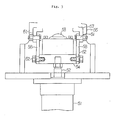
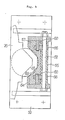
- Fig. 7 which shows a general construction of a tire vulcanizing machine
- installation bases A is installed a double-based frame 1, and in this frame are disposed two sets of vulcanizing apparatuses of the same shape.
- the vulcanizing apparatus includes upper and lower metal molds 26 and 27, the lower metal mold 26 is mounted to the frame 1 via a lower heat plate 3, and the upper metal mold 27 is mounted to a bolster plate 5 via an upper heat plate 7. It is to be noted that the bolster plate 5 is connected to elevator cylinders 100, so that the upper metal mold can be retreated upwards before and after a tire vulcanizing work.
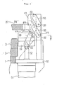
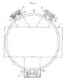
- reference numeral 50 designate support plates extended from the frame, which are provided at three locations along the circumference of the lower metal mold 26.
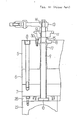
- Reference numeral 51 designates a hydraulic cylinder fixed to the lower surface of the same support plate 50 at an approximately vertical attitude, and its piston rod 52 extends upwards as penetrating through the support plate 50.
- Reference numeral 53 designates a non-directional bearing of spherical shape provided on a bracket 54 at the tip end of the piston rod 52, and this bearing 53 forms a metal mold support member jointly with the above-described hydraulic cylinder 51.
- Reference numeral 55 designates a bracket vertically fixed to the aforementioned support plate 50, a centering member 57 is connected to this bracket 55 via two parallel links 56, and the bottom end of the centering member 57 is connected to the bracket 54 of the piston rod 52 via a link 58.
- Reference numerals 59, 60, 61 and 62 designate pins for pivotably coupling the links 56 and 58, respectively, to the centering member 57 and the bracket 54.
- a centering surface 63 having a V-shaped horizontal cross-section and a lower clamp claw 64 for fixing the lower metal mold.
- Reference numeral 65 designates a centering surface having a V-shaped horizontal cross-section, which is formed on the outer circumferential surface of the lower metal mold 26 as opposed to the centering member 57.
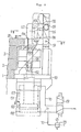
- the hydraulic cylinder 51 is partitioned by a piston 66 into upper and lower pressure chambers 67 and 68, and pressurized fluid feed/exhaust lines 70 and 71 are connected to these pressure chambers via a switching valve 69.
- Reference numeral 72 designates an exhaust line branched from the pressurized fluid line 71 between the lower pressure chamber 68 and the switching valve 69, a relief valve 73 is provided in this branched line, and pressurized fluid having a pressure higher than a predetermined pressure is exhausted to the outside of the cylinder through this relief valve 73.
- the centering member 57 connected to the piston rod 52 via the link 58 is pulled downwards, and also it performs parallel translation towards the center of the vulcanizing machine by rotation of the parallel links 56 about the fulcrum pins 59 and 60, and thus pushes the metal mold on the bearing 53 towards the center of the vulcanizing machine.
- the centering surface 63 provided on the inside surface of the centering member 57 and having a V-shaped cross-section fits to the centering surface 65 provided on the side of the metal mold, and thereby centering in the circumferential direction of the metal mold is also effected (the state shown in Fig. 2). Under this condition, if pressurized fluid for clamping is fed to the upper pressure chamber 67 by manipulating the switching valve 69, then the lower metal mold 26 is fixedly pressed onto the surface of the lower heat plate 3 by means of the clamp claw 64.
- Fig. 6 the devices shown at a and c are illustrated under the condition where the centering member 57 is at the raised position (Fig. 1), while the device shown at b is illustrated under the condition where the centering member is at the lowered position (Fig. 2).
- the subject device is provided with a plurality of hydraulic cylinders each having a piston rod equipped with a non-directional bearing at its top portion and erected on a vulcanizing machine frame close to an outer circumference of a metal mold, a centering member having its outside portion connected to the vulcanizing machine frame via a parallel linkage and having its bottom portion connected to the piston rod via a link, centering surfaces formed on the inside surface of the centering member and the outer circumferential surface of a lower metal mold, respectively, as opposed to each other, and a clamp claw formed at the upper portion of the inside surface of the centering member and adapted to be engaged with the edge of the lower metal mold, the following advantages are obtained:
Landscapes
- Engineering & Computer Science (AREA)
- Mechanical Engineering (AREA)
- Moulds For Moulding Plastics Or The Like (AREA)
- Heating, Cooling, Or Curing Plastics Or The Like In General (AREA)
Applications Claiming Priority (2)
| Application Number | Priority Date | Filing Date | Title |
|---|---|---|---|
| JP283801/88 | 1988-11-11 | ||
| JP63283801A JPH0637057B2 (ja) | 1988-11-11 | 1988-11-11 | タイヤ加硫機の金型芯合せ兼クランプ装置 |
Publications (3)
| Publication Number | Publication Date |
|---|---|
| EP0368286A2 true EP0368286A2 (fr) | 1990-05-16 |
| EP0368286A3 EP0368286A3 (fr) | 1991-12-27 |
| EP0368286B1 EP0368286B1 (fr) | 1994-09-14 |
Family
ID=17670320
Family Applications (1)
| Application Number | Title | Priority Date | Filing Date |
|---|---|---|---|
| EP89120707A Expired - Lifetime EP0368286B1 (fr) | 1988-11-11 | 1989-11-08 | Dispositif de centrage et de serrage pour moule métallique pour un appareil de vulcanisation de pneus |
Country Status (5)
| Country | Link |
|---|---|
| US (1) | US4955799A (fr) |
| EP (1) | EP0368286B1 (fr) |
| JP (1) | JPH0637057B2 (fr) |
| KR (1) | KR910008056B1 (fr) |
| DE (1) | DE68918224T2 (fr) |
Cited By (1)
| Publication number | Priority date | Publication date | Assignee | Title |
|---|---|---|---|---|
| DE4120657A1 (de) * | 1991-06-22 | 1992-12-24 | Krupp Maschinentechnik | Reifenheizpresse mit wechselbaren reifenformteilen |
Families Citing this family (3)
| Publication number | Priority date | Publication date | Assignee | Title |
|---|---|---|---|---|
| US5118269A (en) * | 1990-10-09 | 1992-06-02 | Cooper Tire & Rubber Company | Mold clamps for a vulcanization press |
| US5773041A (en) * | 1997-06-11 | 1998-06-30 | Mcneil & Nrm, Inc. | Mold clamping system |
| EP1997608A3 (fr) | 2007-05-16 | 2009-05-27 | Entex Rust & Mitschke GmbH | Procédé de traitement de produits de dégazage |
Family Cites Families (9)
| Publication number | Priority date | Publication date | Assignee | Title |
|---|---|---|---|---|
| US3464090A (en) * | 1967-09-26 | 1969-09-02 | Nrm Corp | Tire curing press |
| US3545050A (en) * | 1969-01-30 | 1970-12-08 | I S I Mfg Inc | Power clamp with pull-back action |
| US3833323A (en) * | 1973-02-26 | 1974-09-03 | Uniroyal Ag | Segmental mold |
| DE2529901A1 (de) * | 1975-07-04 | 1977-06-02 | Zemme Franz | Vulkanisiermaschine zur herstellung oder erneuerung von reifen mit einspannvorrichtungen zwecks verspannung scheibenfoermiger elemente eines druckstockes |
| AT339757B (de) * | 1975-10-03 | 1977-11-10 | Polyair Maschinenbau Gmbh | Vorrichtung zum giessen oder spritzen von fahrzeugreifen |
| DE3444688C2 (de) * | 1984-12-07 | 1995-12-07 | Krupp Ag Hoesch Krupp | Reifenheizpresse |
| US4601648A (en) * | 1985-09-09 | 1986-07-22 | Kabushiki Kaisha Kobe Seiko Sho | Mold clamp mechanism for tire press |
| DE3631533A1 (de) * | 1986-09-17 | 1988-03-24 | Herbert Maschbau Kg | Reifenvulkanisierform |
| JPH01197207A (ja) * | 1988-01-29 | 1989-08-08 | Hitachi Ltd | 入出庫棚決定運用システム |
-
1988
- 1988-11-11 JP JP63283801A patent/JPH0637057B2/ja not_active Expired - Lifetime
-
1989
- 1989-11-08 DE DE68918224T patent/DE68918224T2/de not_active Expired - Lifetime
- 1989-11-08 EP EP89120707A patent/EP0368286B1/fr not_active Expired - Lifetime
- 1989-11-09 US US07/433,775 patent/US4955799A/en not_active Expired - Lifetime
- 1989-11-11 KR KR1019890016358A patent/KR910008056B1/ko not_active Expired
Cited By (2)
| Publication number | Priority date | Publication date | Assignee | Title |
|---|---|---|---|---|
| DE4120657A1 (de) * | 1991-06-22 | 1992-12-24 | Krupp Maschinentechnik | Reifenheizpresse mit wechselbaren reifenformteilen |
| EP0520253A3 (en) * | 1991-06-22 | 1993-06-30 | Krupp Maschinentechnik Gesellschaft Mit Beschraenkter Haftung | Tyre vulcanisation press with exchangeable tyre-moulding components |
Also Published As
| Publication number | Publication date |
|---|---|
| EP0368286B1 (fr) | 1994-09-14 |
| JPH0637057B2 (ja) | 1994-05-18 |
| DE68918224D1 (de) | 1994-10-20 |
| KR900007585A (ko) | 1990-06-01 |
| EP0368286A3 (fr) | 1991-12-27 |
| JPH02130110A (ja) | 1990-05-18 |
| KR910008056B1 (ko) | 1991-10-07 |
| DE68918224T2 (de) | 1995-03-09 |
| US4955799A (en) | 1990-09-11 |
Similar Documents
| Publication | Publication Date | Title |
|---|---|---|
| EP0115431B1 (fr) | Mécanisme de verrouillage pour des moules d'une presse de vulcanisation de pneumatiques | |
| JP2022518609A (ja) | パルプ・モールド生産ライン及び加工方法 | |
| EP2239129B1 (fr) | Mécanisme de centrage pour machine de vulcanisation de pneus | |
| EP0368286B1 (fr) | Dispositif de centrage et de serrage pour moule métallique pour un appareil de vulcanisation de pneus | |
| US4964792A (en) | Upper metal mold clamp device in a tire vulcanizing machine | |
| US3134136A (en) | Tire carcass loading apparatus for tire curing press | |
| CN201009396Y (zh) | 轮胎胎胚装胎装置 | |
| JP3569170B2 (ja) | タイヤ加硫機の中心機構 | |
| CN109138896B (zh) | 修井装备 | |
| CN114273902B (zh) | 一种轮胎拧紧系统 | |
| JPH0710554A (ja) | ガラス器フォーミングマシン | |
| JPS5970535A (ja) | タイヤ加硫機の金型交換方法 | |
| KR100397749B1 (ko) | 타이어 가황 설비 | |
| JPS61197207A (ja) | タイヤ加硫用金型のクランプ装置 | |
| CN221969012U (zh) | 工程胎硫化机机组 | |
| CN221581819U (zh) | 汽车底梁成型压弯模具 | |
| CN120269863B (zh) | 一种橡胶轮胎生产用胶囊硫化机 | |
| CN113798886A (zh) | 一种加工凸圆叉顶针孔的气动夹具 | |
| CN223850063U (zh) | 硫化机 | |
| CN224132713U (zh) | 一种用于胶水灌装生产线的自动刮胶装置 | |
| CN223686040U (zh) | 硫化机 | |
| JPS6356057B2 (fr) | ||
| JP2955119B2 (ja) | タイヤ加硫機用ローダ装置 | |
| CN213730486U (zh) | 一种模具精密镶件数控加工用多工位夹具 | |
| CN109366518B (zh) | 轮胎硫化机抓胎器法兰式连接机构 |
Legal Events
| Date | Code | Title | Description |
|---|---|---|---|
| PUAI | Public reference made under article 153(3) epc to a published international application that has entered the european phase |
Free format text: ORIGINAL CODE: 0009012 |
|
| 17P | Request for examination filed |
Effective date: 19891205 |
|
| AK | Designated contracting states |
Kind code of ref document: A2 Designated state(s): DE FR GB IT |
|
| PUAL | Search report despatched |
Free format text: ORIGINAL CODE: 0009013 |
|
| AK | Designated contracting states |
Kind code of ref document: A3 Designated state(s): DE FR GB IT |
|
| 17Q | First examination report despatched |
Effective date: 19931019 |
|
| GRAA | (expected) grant |
Free format text: ORIGINAL CODE: 0009210 |
|
| AK | Designated contracting states |
Kind code of ref document: B1 Designated state(s): DE FR GB IT |
|
| ITF | It: translation for a ep patent filed | ||
| REF | Corresponds to: |
Ref document number: 68918224 Country of ref document: DE Date of ref document: 19941020 |
|
| ET | Fr: translation filed | ||
| PLBE | No opposition filed within time limit |
Free format text: ORIGINAL CODE: 0009261 |
|
| STAA | Information on the status of an ep patent application or granted ep patent |
Free format text: STATUS: NO OPPOSITION FILED WITHIN TIME LIMIT |
|
| 26N | No opposition filed | ||
| REG | Reference to a national code |
Ref country code: GB Ref legal event code: IF02 |
|
| PGFP | Annual fee paid to national office [announced via postgrant information from national office to epo] |
Ref country code: DE Payment date: 20081107 Year of fee payment: 20 |
|
| PGFP | Annual fee paid to national office [announced via postgrant information from national office to epo] |
Ref country code: IT Payment date: 20081126 Year of fee payment: 20 |
|
| PGFP | Annual fee paid to national office [announced via postgrant information from national office to epo] |
Ref country code: FR Payment date: 20081112 Year of fee payment: 20 |
|
| PGFP | Annual fee paid to national office [announced via postgrant information from national office to epo] |
Ref country code: GB Payment date: 20081105 Year of fee payment: 20 |
|
| REG | Reference to a national code |
Ref country code: GB Ref legal event code: PE20 Expiry date: 20091107 |
|
| PG25 | Lapsed in a contracting state [announced via postgrant information from national office to epo] |
Ref country code: GB Free format text: LAPSE BECAUSE OF EXPIRATION OF PROTECTION Effective date: 20091107 |