EP0368337B1 - Système de commande d'une machine industrielle - Google Patents
Système de commande d'une machine industrielle Download PDFInfo
- Publication number
- EP0368337B1 EP0368337B1 EP89120886A EP89120886A EP0368337B1 EP 0368337 B1 EP0368337 B1 EP 0368337B1 EP 89120886 A EP89120886 A EP 89120886A EP 89120886 A EP89120886 A EP 89120886A EP 0368337 B1 EP0368337 B1 EP 0368337B1
- Authority
- EP
- European Patent Office
- Prior art keywords
- data
- memory
- machine
- mechanical coordinate
- control
- Prior art date
- Legal status (The legal status is an assumption and is not a legal conclusion. Google has not performed a legal analysis and makes no representation as to the accuracy of the status listed.)
- Expired - Lifetime
Links
Images


Classifications
-
- G—PHYSICS
- G05—CONTROLLING; REGULATING
- G05B—CONTROL OR REGULATING SYSTEMS IN GENERAL; FUNCTIONAL ELEMENTS OF SUCH SYSTEMS; MONITORING OR TESTING ARRANGEMENTS FOR SUCH SYSTEMS OR ELEMENTS
- G05B19/00—Program-control systems
- G05B19/02—Program-control systems electric
- G05B19/18—Numerical control [NC], i.e. automatically operating machines, in particular machine tools, e.g. in a manufacturing environment, so as to execute positioning, movement or co-ordinated operations by means of program data in numerical form
- G05B19/402—Numerical control [NC], i.e. automatically operating machines, in particular machine tools, e.g. in a manufacturing environment, so as to execute positioning, movement or co-ordinated operations by means of program data in numerical form characterised by control arrangements for positioning, e.g. centring a tool relative to a hole in the workpiece, additional detection means to correct position
-
- G—PHYSICS
- G05—CONTROLLING; REGULATING
- G05B—CONTROL OR REGULATING SYSTEMS IN GENERAL; FUNCTIONAL ELEMENTS OF SUCH SYSTEMS; MONITORING OR TESTING ARRANGEMENTS FOR SUCH SYSTEMS OR ELEMENTS
- G05B19/00—Program-control systems
- G05B19/02—Program-control systems electric
- G05B19/18—Numerical control [NC], i.e. automatically operating machines, in particular machine tools, e.g. in a manufacturing environment, so as to execute positioning, movement or co-ordinated operations by means of program data in numerical form
- G05B19/414—Structure of the control system, e.g. common controller or multiprocessor systems, interface to servo, programmable interface controller
- G05B19/4147—Structure of the control system, e.g. common controller or multiprocessor systems, interface to servo, programmable interface controller characterised by using a programmable interface controller [PIC]
-
- G—PHYSICS
- G05—CONTROLLING; REGULATING
- G05B—CONTROL OR REGULATING SYSTEMS IN GENERAL; FUNCTIONAL ELEMENTS OF SUCH SYSTEMS; MONITORING OR TESTING ARRANGEMENTS FOR SUCH SYSTEMS OR ELEMENTS
- G05B19/00—Program-control systems
- G05B19/02—Program-control systems electric
- G05B19/18—Numerical control [NC], i.e. automatically operating machines, in particular machine tools, e.g. in a manufacturing environment, so as to execute positioning, movement or co-ordinated operations by means of program data in numerical form
Definitions
- This invention relates to an industrial machine control device for controlling machine tools and other industrial machines, and more particularly to an industrial machine control device in which a first control unit, namely, a numerical control device applies mechanical coordinate data to a second control unit, namely, a programmable controller at all times, and the programmable controller monitors the mechanical coordinate data, thereby to perform a sequence operation as required.
- a first control unit namely, a numerical control device applies mechanical coordinate data to a second control unit, namely, a programmable controller at all times
- the programmable controller monitors the mechanical coordinate data, thereby to perform a sequence operation as required.
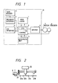
- FIG. 1 is a block diagram showing the arrangement of a conventional industrial machine control device, namely, a numerical control device (hereinafter referred to as "an NC device", when applicable).
- FIG. 2 is an explanatory diagram showing a machine to be controlled the device.
- reference numeral 1 designates a memory made up of a RAM for storing programs and data; 2, a control section essentially comprising a CPU 2a, the control section operating to control the functions of the NC device according to the system software loaded therein; 3, an arithmetic section for performing numerical arithmetic operation under the control of the control section; 4, a tape reader for reading data from a paper tape in which an NC machining program (hereinafter referred to merely as "a machining program”, when applicable) has been recorded by punching; 5, a program interface; 6, a drive section including a servo amplifier etc.; 7, a motor for driving a machine to be controlled (hereinafter referred to merely as "a machine:, when applicable); 8, an encoder for outputting a feedback signal; and 9, an input/output interface provided for input signals necessary for starting and stopping the NC device, and output signals such as NC device state signals, and auxiliary function signals for allowing the NC device to control external equipment.
- the machining program may be recorded on a f
- reference numeral 20 designates a speed reducer; 21, a drive mechanism such as a ball screw; 22, a movable table of the machine, which is a tool mounting stand in the case of a lathe; and 23a, 23b, 23c and 23d, limit switches mounted on a stationary part of the machine, for outputting signals representing the current position of the movable table 22; i.e., the arrival of the machine at predetermined positions (hereinafter referred to as "predetermined position arrival signals", when applicable).
- the machine Under the control of the NC device 10, the machine operates to machine a workpiece (not shown).
- the above-described predetermined position arrival signals are applied, for instance, to a programmable controller (not shown, and hereinafter referred to merely as "a PC", when applicable).
- a PC programmable controller
- the preparatory operation of a workpiece conveying device (not shown) is carried out, so that a workpiece machined is conveyed out of the machine without delay, according to the control operation of the programmable controller.
- the predetermined position arrival signals are used not only for achieving the preparatory operation of the workpiece conveying device, but also for performing sequence operations when the movable table reaches the predetermined positions.
- some detectors such as limit switches are provided at the predetermined positions to output the predetermined position arrival signals.
- the detectors are relatively short in service life. Therefore, the employment of the NC device is low in reliability and not so economical.
- a device showing the features of the preamble of claim 1 is known from EP-A-0 137 852.
- an object of this invention is to eliminate the above-described difficulty accompanying a conventional NC device.
- Another objection of the invention is to provide an industrial machine control device which can provide a predetermined position arrival signal with no detectors attached to an industrial machine.
- the other object of the invention is to provide an industrial machine control device which, with no detectors attached to an industrial machine to be controlled, gives a sequence control to the machine when the movable table reaches an aimed predetermined position.
- an industrial machine control device comprising:
- an industrial machine control device comprising:
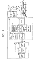
- FIG. 3 is an explanatory diagram, partly as a block diagram, showing the arrangement of one embodiment of this invention.
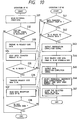
- FIG. 4 is a flow chart for a description of the operation of the embodiment shown in FIG. 3.
- reference numeral 11 designates a mechanical coordinate data memory which, during the control of a machine to be controlled, stores the mechanical coordinate data corresponding to the present position of the machine which is calculated by the arithmetic section 3 under the control of the control section 2 at all times; 15, a workpiece; 16, a tool; 26, a spindle; 27, a spindle motor; 28, a spindle controller for controlling the spindle motor; and a, b and c, the predetermined positions of the machine where a sequence control is given to the machine - for instance, when the movable table 22 reaches the point a, the workpiece conveying device is caused to prepare to convey the workpiece out of the machine.
- reference numeral 30 designates a programmable controller for performing sequence control according to a predetermined program
- a CPU central processing unit
- reads a program out of memory according to a predetermined sequence decodes the instruction words thereof, and performs, according to the contents of the instruction words, the loading of input data, logical operations and other operations, and transmission of output data
- 32 a memory for storing programs, the results of operations, and necessary data
- 33a and 33b input/output interfaces.
- programmable controller as used herein is intended to mean a control unit which fundamentally comprises the above-described circuit elements 31, 32, and 33a and 33b, and it may be a personal computer or the like (hereinafter referred to as "a PC", when applicable).
- a parallel bus 35 is connected between the NC device 10 and the PC 30 through the input/output interfaces 33a and 33b, so that control signals and state signals are transmitted therebetween through the parallel bus 35.
- Step S100 the present position of the machine is calculated by the arithmetic section 3 with the aid of the control section 2.
- the mechanical coordinate data corresponding to the present position thus calculated is stored in the mechanical coordinate data memory 11.
- Step S200 the data stored in the mechanical coordinate data memory 11 is applied through the data bus 35 to the PC 30 at all times.
- the broken line arrow indicates the transfer of the data through the bus 35.
- Step S210 the PC reads the mechanical coordinate data transferred from the NC device 10. Then, in Step S220, it is determined whether or not the mechanical coordinate value coincides with the aimed value. If "yes”, in Step S230, the PC gives a sequence control to the machine.
- the sequence operation of the machine is carried out when the movable table 22 arrives at the predetermined position.
- the aimed position can be readily changed by changing the data set in the memory of the PC 30.
- the operation of the NC is such that, as shown in FIG. 5, only when an operation according to one program is ended, an operation according to the following program can be started.
- reference character (1) designates the movement of a shaft; (2), the replacement of a tool; and (3), the vertical movement of an arm.
- Those operations (1), (2), and (3) are carried out in the stated order.
- the sequence operation can be performed under the control of the PC 30, with the result that the machining time can be reduced as much.
- the replacement of a tool by an automatic tool exchanging device is, in general, carried out after the machine has been returned to the original point.
- a critical position may be provided before the original point, at which position the tool can be replaced without touching other parts; that is, it can be handled in safety.
- the sequence operation i.e., the replacement of the tool can be performed at the critical point thus selected, and the machining time can be reduced.
- a limit switch may be used.
- the employment of the limit switch is disadvantageous in that it will take a lot of time to position the limit switch.
- the critical position may be determined by using a timer.
- the use of the time is also disadvantageous in that the timer itself is variable in characteristic, and it is rather difficult to set a time instance suitable for determination of the critical position.
- the above-described embodiment of the invention can positively determine the critical position.
- the invention can readily handle them, with different aimed values set for different workpieces.
- the NC device 10 applies mechanical coordinate data to the PC 30 at all times, and the PC 30 refers to the data when necessary. Therefore, it is unnecessary to provide a procedure for the transmission of data between the NC device 10 and the PC 30. For instance, the following procedure is unnecessary:
- the PC 30 issues a data request, the NC device 10 discriminates the request code, and reads the data requested such as for instance the present position data, and applied it to the interface; and the PC 30 loads the data, and so forth. Hence, the necessary data can be obtained without time delay.
- the data may be obtained by using the predetermined procedure.
- the machine will move to another position while operation is being performed according to the procedure, and therefore the obtained data are useless.
- the invention is advantageous in that necessary data can be obtained without a procedure; i.e., without time delay.
- the mechanical coordinate data corresponding to the present position of a machine to be controlled which is calculated by the first control unit adapted to numerically control the machine is applied at all times to the second control unit adapted to perform the sequence control of the machine, and the second control unit monitors the mechanical coordinate data inputted, and outputs a signal when the data coincides with the aimed value. Therefore, the industrial machine control device is high in reliability and excellent in economy, and it can change the predetermined position freely where the machine is operated sequentially. Furthermore, the control device of the invention can allow the machine to perform its sequential operation during one block of operation according to the machining program.
- FIG. 6 is an explanatory diagram, partly as a block diagram, showing the arrangement of a second embodiment of this invention
- FIG. 7 is a flow chart for a description of the operation of the second embodiment shown in FIG. 6.
- reference characters 15a, 15b and 15c designate workpieces different in kind; i.e., in configuration, in material and in the contents of machining.
- different tools 16 must be used for machining the different workpieces. More specifically, the tool used for machining the workpiece 15a must be replaced with another tool when the next workpiece 15b is machined, and the tool used for the latter 15b must be replaced with another tool when the remaining workpiece 15c is machined.
- FIG. 6 shows the case where the second workpiece 15b is machined.
- the second workpiece 15b is going to be machine
- the first workpiece 15a has been machined and conveyed out of the machine
- the third workpiece 15c will be machined after the second workpiece 15b; that is, it is going to be conveyed in the machine.
- the one-dot-chain line indicates the direction of flow of workpieces.
- reference characters 17a, 17b and 17c designate sensors for identifying the kinds of workpieces; 26, a spindle; 27, a spindle motor; and 28, a spindle controller for controlling the spindle motor.
- reference numeral 11 designates a memory for storing mechanical coordinate data inputted by the PC 30.
- mechanical coordinate data as used herein is intended to mean the data that, in the case where, as was described before, the preparatory operation of the workpiece conveying device is performed before the machining of a workpiece has been accomplished, indicates the mechanical coordinates of the predetermined position where, upon arrival of the movable table 22, the preparatory operation of the workpiece conveying device is started.
- first memory as used herein is intended to means the mechanical coordinate data memory 11.
- reference numeral 12 designates a region data memory for storing region data in advance.
- region data as used herein is intended to mean the data that determines a mechanical coordinate region so that, when the movable table 22 goes in the region, the predetermined position arrival signal is produced.
- the machine's current position data i.e., the present position data of the movable table 22 is calculated by the arithmetic section with the aid of the control section 2 at all times, and therefore the NC device 10 can detect the position of the predetermined part of the machine relatively accurately.
- the NC device outputs a signal when the movable table 22 reaches a predetermined position, it can output the signal only at the time instant when the current position of the movable table 22 coincides with the mechanical coordinate value of the predetermined position, because the movable table 22 being moved will pass the aimed position quickly. Accordingly, the external equipment, namely, the PC cannot detect the signal.
- the predetermined position arrival signal should have a certain width.
- the PC it is unnecessary that the occurrence of the signal is accurate to an extent of 1 ⁇ ; that is, the signal should be outputted with a time width of around 1 mm.
- the signal is outputted when the current position of the machine comes in the mechanical coordinate region determined by the region data with respect to the aimed predetermined position.
- the data for determining the region is referred to as "region data”.
- mechanical coordinate region as used herein is intended to mean the region which is defined by A+B and A-B where A is the mechanical coordinate data, and B is the region data.
- second memory as used herein is intended to mean the region data memory 12.
- reference numeral 13 designates a present position data memory for storing the present position data which is calculated by the arithmetic section 3 with the aid of the control section 2 when the machine is under the control of the NC machine.
- the present position data memory 13 will be referred to as "a third memory", when applicable.
- Step S1 the PC reads external conditions.
- Step S1 the PC 30 operates in accordance with the sequence control procedure, to unload the workpiece 15a from the movable table 22, and then to load the workpiece 15b on it 22. Then, the PC 30 receives the output signal of the sensor 17b to detect the kind of the workpiece 15b.
- a machining program has been predetermined for the workpiece. Therefore, upon detection of the kind of the workpiece, the PC 30 transmits a machining program section signal through the bus 35 to the NC machine 10. In response to the selection signal, the NC device 10 selects the machining program for the workpiece 15b. The machining program specifies a tool to be used for machining the workpiece 15b, and the NC device 10 transmits a tool specifying signal through the bus 35 to the PC 30. In response to the tool specifying signal, the PC operates to exchange the tool.
- Step S2 it is determined whether or not the predetermined position arrival signal is necessary for the workpiece. If "yes”, then in Step S3 the PC prepares to apply a mechanical coordinate data to the NC device 10. That is, the PC has known (by programming) that, when the machine; i.e., the movable table arrives at a predetermined position, it needs a signal indicating the arrival. Therefore, the PC selects the mechanical coordinate data corresponding to the workpiece among the those stored; for instance a mechanical coordinate data A indicating the position (a) in FIG. 1, and prepares to transmit it to the NC device 10.
- Step S4 the PC issues a data transfer request to the NC device 10.
- Step S5 it is determined whether the NC device 10 has prepared to receive a mechanical coordinate data. If “no”, Step S4 is effected again. If “yes”, in Step S6, the mechanical coordinate data A is transferred to the NC device 10.
- Step S7 the PC reads the data reception state of the NC device 10.
- Step S8 it is determined whether or not the NC device 10 has received the data. If “no”, Step S7 is effected again. If “yes”, the operation is ended. In the case where, in Step S2, the result is "no", the operation is ended, because the predetermined position arrival signal is not needed.
- Step S11 it is determined whether or not the NC device has received the data transmission request from the PC 30. If “yes”, then in Step S12, it is determined whether or not the NC device is ready to receive the data. If “yes”, then in Step S13, the NC device 10 outputs a preparation completion signal.
- Step S14 the NC device receives the mechanical coordinate data A from the PC 30, and stores it in a buffer memory included in the input/output interface.
- Step S15 the NC device supplies a data reception completion signal to the PC 30, and then in Step S16 the mechanical coordinate data A is transferred from the buffer memory to first the memory 11, where it is stored. Thus, the operation I of the NC device is ended.
- the NC device 10 When the data has been stored in the first memory 11 in the above-described manner, the NC device 10 will perform an operation II, with respect to the outputting of a predetermined position arrival signal, according to a flow chart of FIG. 8.
- Step S21 by using the data stored in the first, second and third memories, a region decision operation is carried out to determine whether or not the movable table 22 has moved into the mechanical coordinate region to output the predetermined position arrival signal.
- This operation is carried out according to the following expression (1): A - B ⁇ C ⁇ A + B where A is the data stored in the first memory, B is the data stored in the second memory, and C is the data stored in the third memory.
- Step S22 it is determined whether or not the machine; i.e., the movable table is in the mechanical coordinate region to output the predetermined position arrival signal. If "yes”; i.e., if expression (1) is satisfied, then in Step S23 the predetermined position arrival signal is outputted.
- the predetermined position arrival signal thus outputted is applied through the bus 35 to the PC 30, and the latter 30 performs a sequence control operation to allow the workpiece conveying device to prepare to convey the workpiece.
- only one predetermined position is provided.
- a plurality of predetermined position arrivals signal are outputted, in the operations of the PC 30 and the NC device 10 as shown in FIG. 8, for instance a plurality of mechanical coordinate data A1, A2 and A3 with data indicating the signal outputting sequence are transferred from the PC 30 to the NC device 10 and stored in the first memory 11.
- the data are read in the above-described sequence; for instance, the data A1 is read, and the signal is outputted, then the data A2 is read, and the signal is outputted, and so forth.
- the workpieces to be machined are different in kind.
- a second embodiment of the invention one and the same workpieces are machined, and the position where the predetermined position arrival signal is outputted is not frequently changed.
- the mechanical coordinate data is stored in the first memory 11 of the NC device 10 in advance, and therefore the predetermined position arrival signal can be applied to the PC 30 according to the operation II of the NC device shown in FIG. 8.
- the burden on the PC 30 is reduced to some extent.
- the third embodiment is equal to the first embodiment except for the contents of the first memory.
- FIG. 9 is an explanatory diagram showing the first memory 11a of the third embodiment.
- the first memory occupies a region in the memory 1 of the NC device 10.
- reference characters A1, A2, A3, and so forth designate the data in the memory 11a; i.e., mechanical coordinate data specified as parameters in advance; and (1), (2), (3) and so forth, mechanical coordinate request code data (hereinafter referred to merely as "request code data", when applicable) for selecting the data A1, A2, A3, and so forth, respectively.
- the request code data as described later, are transferred from the PC 30 to the NC device 10, and serve as selection signals for selecting the mechanical coordinate data.
- FIG. 10 is a flow chart for a description of the operation of the third embodiment. The operation of the fourth embodiment of the invention will be described with reference to the flow chart.
- Step S31 the PC reads external conditions.
- Step S32 it is determined whether or not a predetermined position arrival signal is necessary for the workpiece. If "yes”, then in Step S33 the PC prepares to apply a request code data to the NC device 10.
- the PC has known it by programming that, when the machine reaches a predetermined position, the NC device needs a signal representing the arrival of the machine to the position. Therefore, the PC reads the corresponding one of the request code data stored, and prepares to transmit it to the NC device. For instance in the case where the signal is needed at the position (a) in FIG.
- Step S34 the PC reads the request code data (1) for selecting the mechanical coordinate data A1 corresponding to the workpiece, and prepares to transmit it to the NC device 10.
- Step S34 the PC 30 issues a data transfer request to the NC device 10.
- Step S35 it is determined whether or not the NC device 10 is ready to receive the data. If “no”, Step S34 is effected again. If “yes”, in Step S36 the PC transmits the request code data (1) to the NC device 10. Then, in Step S37, the PC detects the data receiving state of the NC device 10.
- Step S38 it is determined whether or not the NC device has received the data. If “no”, then Step S37 is effected again. If “yes”, the operation is ended. If, in Step 32, the result of determination is "no", the operation is ended, because no predetermined position arrival signal is needed.
- Step S41 it is determined whether or not the NC device has received a data transfer request from the PC 30. If “yes”, in Step S42 it is determined whether or not th NC device is ready to receive data. If “yes”, in Step S43 the NC device outputs a preparation completion signal. Then, in Step S44, the request code data (1) transmitted from the PC 30 is read, and stored in a buffer memory included in the input/output interface. In Step S45 the NC device applies a data reception completion signal to the PC 30, and then in Step 46 access is made to the memory 11a to select the mechanical coordinate data A1 corresponding to the request code data (1). In Step S47, the mechanical coordinate data A1 thus selected is stored in a data processing memory. Thus, the operation I of the NC device 10 has been ended.
- broken line arrows indicate the transfer of data through the bus 35.
- the operation of outputting the predetermined position arrival signal after the storage of the mechanical coordinate data in the data processing memory is equal to that in the first embodiment shown in FIG. 8 except that, in Step S21 of the flow chart shown in FIG. 8, the mechanical coordinate data for arithmetic operation are the data stored in the first memory 11 in the first embodiment, and the -data stored in the data processing memory in the third embodiment.
- FIG. 11 is a flow chart for a description of the operation of the fourth embodiment.
- data on mechanical coordinates are not transmitted between the PC 30 and the NC device 10.
- the PC 30 detects the kind of a workpiece 15, and applies a machining program selecting instruction to the NC device. In response to the instruction, the NC device selects a machining program. According to the tool specifying signal, the tool is exchanged with the aid of the PC 30.
- the machine is operated under the control of the NC device 10, to machine the workpiece.
- Step S51 mechanical coordinate data and region data are specified according to the machining program
- Step S52 the operating condition of the machine is read.
- Step S53 it is determined that both of the data can be set. If "no”, Step S52 is effected again. If "yes”, in Step S54 the mechanical coordinate data and region data specified by the machining program are stored in the first and second memories 11 and 12, respectively.
- the operation I has been ended.
- the mechanical coordinate data and the region data are stored in the first memory 11 and the second memory 12, respectively.
- An operation II of outputting a predetermined position arrival signal after the storage of the mechanical coordinate data and the region data in the first memory 11 and the second memory 12 is the same as Steps S21 through S23 in FIG. 8.
- the fifth embodiment may be so designed that, as in the third embodiment, a plurality of mechanical coordinate data have been stored in advance, and one of those data is selected in correspondence to the request code data inputted according to the machining program.
- the fourth or fifth embodiment only one predetermined position is provided, and the workpieces to be handled are different in kind.
- the technical concept of the third or fourth embodiment is applicable to the case, too, where a plurality of predetermined position arrival signals are outputted, and a number of workpieces of one kind are machined.
- the mechanical coordinate data of a predetermined position of the machine is transferred from the PC, and the predetermined position arrival signal is outputted according to the data thus transferred, the region data and the current position data.
- the numerical control device of the invention is high in reliability and excellent in economy, and it can freely change the position where the predetermined position arrival signal.
- the mechanical coordinate data of a predetermihed position of the machine has been stored in advance, and the predetermined position arrival signal is outputted according to the data thus stored, the region data and the current position data, thus eliminating the transferring of the mechanical coordinate data from the PC to the NC device.
- the numerical control device has an effect of reducing the burden of the PC as well as the effect of the NC device provided according to the first aspect of the invention.
- the mechanical coordinate data of a predetermined position of the machine is specified according to the machining program, and the predetermined position arrival signal is outputted according to the mechanical coordinate data thus specified, the region data and the current position data. Therefore, the NC device has an effect that a sequence operation can be performed during one block of operations, in addition to the effect of the NC device provided according to the first aspect of the invention.
Landscapes
- Engineering & Computer Science (AREA)
- Human Computer Interaction (AREA)
- Manufacturing & Machinery (AREA)
- Physics & Mathematics (AREA)
- General Physics & Mathematics (AREA)
- Automation & Control Theory (AREA)
- Numerical Control (AREA)
Claims (5)
- Dispositif de commande d'une machine industrielle comprenant:une première unité de commande (10) comprenant un moyen de traitement de données (2) présentant une mémoire (1) et une unité centrale (2a) pour analyser et utiliser des données de coordonnées mécaniques introduites par l'intermédiaire d'un dispositif d'introduction (4, 5, 9), ledit moyen de traitement de données pouvant être utilisé pour commander de manière numérique une machine industrielle (15, 22, 26, 27) en fonction d'un signal de sortie dudit moyen de traitement de données (2), et un moyen (9) pour délivrer à tout instant des données calculées de position actuelle, qui sont calculées par ledit moyen de traitement de données (2);une deuxième unité (30) de commande comprenant au moins une mémoire (32) et une unité centrale (31) pour effectuer, selon un programme prédéterminé, un commande de la séquence de ladite machine; etun bus (35) connecté entre ladite première (10) et ladite seconde (30) unité de commande, pour la transmission de données entre elles;caractérisé en ce que la seconde unité de commande comprend un moyen pour contrôler lesdites données calculées de position actuelle délivrées par ladite première unité (10) de commande, pour fournir un signal lorsque les données calculées de position actuelle coïncident avec une position prédéterminée.
- Dispositif de commande d'une machine industrielle comprenant:une unité de commande (10), comprenant un moyen de traitement de données possédant une mémoire (1) et une unité centrale (2a), pour analyser et utiliser des données de coordonnées mécaniques introduites par l'intermédiaire d'un dispositif d'introduction (4, 5, 9), ledit moyen de traitement de données étant utilisable pour commander numériquement une machine industrielle, en fonction d'un signal de sortie dudit moyen de traitement de données, ladite mémoire (1) comprenant une première mémoire (11) pour conserver les données de coordonnées mécaniques de ladite machine; caractérisé en ce que la dite mémoire (1) comporte en outre:une seconde mémoire (12) pour conserver à l'avance des données de région pour déterminer une région de coordonnées mécaniques dans laquelle est délivré un signal d'arrivée dans une position prédéterminé, qui indique l'arrivée de ladite machine dans une position prédéterminée;une troisième mémoire de données (13) pour conserver des données de position actuelle calculées de ladite machine, délivrées par ledit moyen de traitement des données; et le dispositif comprenant en outre:un moyen pour délivrer le signal d'arrivée dans une position prédéterminée lorsque la valeur de ladite troisième mémoire (13) arrive dans la région de coordonnées mécaniques qui est calculée à partir des données conservées dans ladite première mémoire (11) et des données conservées dans ladite seconde mémoire (12).
- Dispositif de commande d'une machine industrielle selon la revendication 2, dans lequel les données de cordonnées mécaniques de ladite machine sont introduites par l'intermédiaire d'un bus (35) par une unité de commande supplémentaire présentant la forme d'un contrôleur programmable (30) pour réaliser une commande de la séquence de ladite machine industrielle.
- Dispositif de commande d'une machine industrielle selon la revendication 2, dans lequel les données de coordonnées mécaniques de ladite machine sont conservées à l'avance dans ladite première mémoire (11), pour fournir un signal indiquant l'arrivée de ladite machine dans une position prédéterminée.
- Dispositif de commande d'une machine industrielle selon la revendication 2, dans lequel les données de coordonnées mécaniques de ladite machine sont spécifiées par un programme d'usinage, et la région de coordonnées mécaniques est également spécifiée par le programme d'usinage.
Applications Claiming Priority (4)
| Application Number | Priority Date | Filing Date | Title |
|---|---|---|---|
| JP284020/88 | 1988-11-11 | ||
| JP63284020A JPH02130606A (ja) | 1988-11-11 | 1988-11-11 | 数値制御装置 |
| JP63293484A JPH02140810A (ja) | 1988-11-22 | 1988-11-22 | 産業用機械の制御装置 |
| JP293484/88 | 1988-11-22 |
Publications (2)
| Publication Number | Publication Date |
|---|---|
| EP0368337A1 EP0368337A1 (fr) | 1990-05-16 |
| EP0368337B1 true EP0368337B1 (fr) | 1996-04-03 |
Family
ID=26555285
Family Applications (1)
| Application Number | Title | Priority Date | Filing Date |
|---|---|---|---|
| EP89120886A Expired - Lifetime EP0368337B1 (fr) | 1988-11-11 | 1989-11-10 | Système de commande d'une machine industrielle |
Country Status (6)
| Country | Link |
|---|---|
| US (1) | US5130919A (fr) |
| EP (1) | EP0368337B1 (fr) |
| KR (1) | KR920005252B1 (fr) |
| CA (1) | CA2002759A1 (fr) |
| DE (1) | DE68926145T2 (fr) |
| HK (1) | HK1004294A1 (fr) |
Families Citing this family (2)
| Publication number | Priority date | Publication date | Assignee | Title |
|---|---|---|---|---|
| CN1066091C (zh) * | 1994-03-24 | 2001-05-23 | 孙传波 | 一种切割石料用龙门切割机床程序控制器 |
| DE102004037259A1 (de) * | 2004-07-31 | 2006-02-16 | Robert Bosch Gmbh | Verfahren zur Einstellung vorgebbarer Parameter |
Family Cites Families (6)
| Publication number | Priority date | Publication date | Assignee | Title |
|---|---|---|---|---|
| US4158226A (en) * | 1977-11-21 | 1979-06-12 | Allen-Bradley Company | Programmable controller with limit detection |
| US4242621A (en) * | 1978-03-27 | 1980-12-30 | Spaulding Carl P | Programmable limit switch for a movable member, particularly a machine tool slide |
| US4401930A (en) * | 1980-12-30 | 1983-08-30 | Toyota Jidosha Kogyo Kabushiki Kaisha | Method of sensing position of movable body and apparatus therefor |
| US4470108A (en) * | 1981-12-01 | 1984-09-04 | Mitsubishi Denki Kabushiki Kaisha | Position detecting device |
| JPS59153205A (ja) * | 1983-02-18 | 1984-09-01 | Fanuc Ltd | 数値制御システム |
| US4744022A (en) * | 1985-06-03 | 1988-05-10 | Autotech Corporation | Programmable control apparatus including an absolute position transducer |
-
1989
- 1989-11-02 KR KR1019890015881A patent/KR920005252B1/ko not_active Expired
- 1989-11-10 EP EP89120886A patent/EP0368337B1/fr not_active Expired - Lifetime
- 1989-11-10 DE DE68926145T patent/DE68926145T2/de not_active Expired - Fee Related
- 1989-11-10 CA CA002002759A patent/CA2002759A1/fr not_active Abandoned
- 1989-11-13 US US07/435,231 patent/US5130919A/en not_active Expired - Lifetime
-
1998
- 1998-04-27 HK HK98103527A patent/HK1004294A1/en not_active IP Right Cessation
Also Published As
| Publication number | Publication date |
|---|---|
| DE68926145T2 (de) | 1996-09-12 |
| KR900008352A (ko) | 1990-06-03 |
| US5130919A (en) | 1992-07-14 |
| DE68926145D1 (de) | 1996-05-09 |
| EP0368337A1 (fr) | 1990-05-16 |
| CA2002759A1 (fr) | 1990-05-11 |
| HK1004294A1 (en) | 1998-11-20 |
| KR920005252B1 (ko) | 1992-06-29 |
Similar Documents
| Publication | Publication Date | Title |
|---|---|---|
| CA1206232A (fr) | Methode de programmation preliminaire des mouvements d'un robot industriel | |
| US4029950A (en) | Numerical control system for machines utilizing a programmable sequence controller | |
| US4288849A (en) | Machine tool control systems | |
| US4550378A (en) | Method of numerical control and device therefor | |
| US4543639A (en) | Industrial robot control method | |
| EP0105158A2 (fr) | Un interface d'adaptation de programme forcé pour un système à commande numérique | |
| EP0106253A2 (fr) | Machine-outil à commande numérique ayant une fonction permettant un retour à la position initiale en cas d'urgence | |
| EP0415445B1 (fr) | Appareil à commande séquentielle avec mémoire séparée et une mémoire à conditions de blocage | |
| US4992712A (en) | Control device for industrial machine | |
| EP0171435B1 (fr) | Procede de commande numerique | |
| EP0368337B1 (fr) | Système de commande d'une machine industrielle | |
| GB2083247A (en) | A programmable machine | |
| EP0107794A1 (fr) | Système à commande numérique | |
| HK1004294B (en) | Industrial machine control device | |
| EP0120473A2 (fr) | Appareil à commande numérique pour machine-outil | |
| EP0360190B1 (fr) | Dispositif de commande pour une machine industrielle | |
| JP2559273B2 (ja) | 数値制御装置および数値制御装置の画面表示方法 | |
| EP0075325A2 (fr) | Dispositif et méthode de commande pour un robot industriel | |
| EP0414911B1 (fr) | Dispositif de commande numerique pour machine de transfert | |
| KR0136695B1 (ko) | 복합수치제어기 | |
| JP7473653B2 (ja) | 制御対象物を制御する設定パラメータを所定のタイミングで変更する機能を有する数値制御装置及びその設定パラメータ変更方法 | |
| JPH02151909A (ja) | 産業用機械の制御装置 | |
| JP2588953B2 (ja) | 数値制御装置 | |
| JPH02140810A (ja) | 産業用機械の制御装置 | |
| KR830002110B1 (ko) | 수치제어 공작 기계의 시이퀀스 제어방식 |
Legal Events
| Date | Code | Title | Description |
|---|---|---|---|
| PUAI | Public reference made under article 153(3) epc to a published international application that has entered the european phase |
Free format text: ORIGINAL CODE: 0009012 |
|
| AK | Designated contracting states |
Kind code of ref document: A1 Designated state(s): DE FR GB |
|
| 17P | Request for examination filed |
Effective date: 19900622 |
|
| 17Q | First examination report despatched |
Effective date: 19930806 |
|
| RBV | Designated contracting states (corrected) |
Designated state(s): DE GB |
|
| GRAA | (expected) grant |
Free format text: ORIGINAL CODE: 0009210 |
|
| AK | Designated contracting states |
Kind code of ref document: B1 Designated state(s): DE GB |
|
| REF | Corresponds to: |
Ref document number: 68926145 Country of ref document: DE Date of ref document: 19960509 |
|
| PLBE | No opposition filed within time limit |
Free format text: ORIGINAL CODE: 0009261 |
|
| STAA | Information on the status of an ep patent application or granted ep patent |
Free format text: STATUS: NO OPPOSITION FILED WITHIN TIME LIMIT |
|
| 26N | No opposition filed | ||
| REG | Reference to a national code |
Ref country code: GB Ref legal event code: 746 Effective date: 19971202 |
|
| PGFP | Annual fee paid to national office [announced via postgrant information from national office to epo] |
Ref country code: GB Payment date: 19991110 Year of fee payment: 11 |
|
| PG25 | Lapsed in a contracting state [announced via postgrant information from national office to epo] |
Ref country code: GB Free format text: LAPSE BECAUSE OF NON-PAYMENT OF DUE FEES Effective date: 20001110 |
|
| GBPC | Gb: european patent ceased through non-payment of renewal fee |
Effective date: 20001110 |
|
| PGFP | Annual fee paid to national office [announced via postgrant information from national office to epo] |
Ref country code: DE Payment date: 20011126 Year of fee payment: 13 |
|
| PG25 | Lapsed in a contracting state [announced via postgrant information from national office to epo] |
Ref country code: DE Free format text: LAPSE BECAUSE OF NON-PAYMENT OF DUE FEES Effective date: 20030603 |