EP0368547A1 - Dispositif et procédé pour la production de plasma - Google Patents
Dispositif et procédé pour la production de plasma Download PDFInfo
- Publication number
- EP0368547A1 EP0368547A1 EP89311290A EP89311290A EP0368547A1 EP 0368547 A1 EP0368547 A1 EP 0368547A1 EP 89311290 A EP89311290 A EP 89311290A EP 89311290 A EP89311290 A EP 89311290A EP 0368547 A1 EP0368547 A1 EP 0368547A1
- Authority
- EP
- European Patent Office
- Prior art keywords
- plasma
- gas
- free
- standing
- plasmas
- Prior art date
- Legal status (The legal status is an assumption and is not a legal conclusion. Google has not performed a legal analysis and makes no representation as to the accuracy of the status listed.)
- Granted
Links
- 238000000034 method Methods 0.000 title claims abstract description 23
- 210000002381 plasma Anatomy 0.000 claims abstract description 502
- 239000007921 spray Substances 0.000 claims abstract description 54
- 238000010438 heat treatment Methods 0.000 claims abstract description 14
- 238000007750 plasma spraying Methods 0.000 claims abstract description 9
- 239000007789 gas Substances 0.000 claims description 162
- 238000012546 transfer Methods 0.000 claims description 60
- 239000002245 particle Substances 0.000 description 32
- 239000000203 mixture Substances 0.000 description 16
- XKRFYHLGVUSROY-UHFFFAOYSA-N Argon Chemical compound [Ar] XKRFYHLGVUSROY-UHFFFAOYSA-N 0.000 description 12
- 239000000463 material Substances 0.000 description 12
- QVGXLLKOCUKJST-UHFFFAOYSA-N atomic oxygen Chemical compound [O] QVGXLLKOCUKJST-UHFFFAOYSA-N 0.000 description 11
- -1 for example Substances 0.000 description 11
- 239000001301 oxygen Substances 0.000 description 11
- 229910052760 oxygen Inorganic materials 0.000 description 11
- 230000006866 deterioration Effects 0.000 description 10
- 238000000576 coating method Methods 0.000 description 9
- 239000011248 coating agent Substances 0.000 description 8
- 239000002826 coolant Substances 0.000 description 7
- 229910052786 argon Inorganic materials 0.000 description 6
- 230000008021 deposition Effects 0.000 description 6
- 238000010891 electric arc Methods 0.000 description 6
- 239000000758 substrate Substances 0.000 description 6
- 239000012159 carrier gas Substances 0.000 description 5
- 238000004891 communication Methods 0.000 description 5
- 238000002347 injection Methods 0.000 description 5
- 239000007924 injection Substances 0.000 description 5
- 229910052751 metal Inorganic materials 0.000 description 5
- 239000000843 powder Substances 0.000 description 5
- 239000000919 ceramic Substances 0.000 description 4
- 238000009826 distribution Methods 0.000 description 4
- 239000012530 fluid Substances 0.000 description 4
- 230000000977 initiatory effect Effects 0.000 description 4
- 239000002184 metal Substances 0.000 description 4
- 239000000243 solution Substances 0.000 description 4
- 238000005507 spraying Methods 0.000 description 4
- PNEYBMLMFCGWSK-UHFFFAOYSA-N Alumina Chemical compound [O-2].[O-2].[O-2].[Al+3].[Al+3] PNEYBMLMFCGWSK-UHFFFAOYSA-N 0.000 description 3
- 239000004020 conductor Substances 0.000 description 3
- 230000003247 decreasing effect Effects 0.000 description 3
- 238000005516 engineering process Methods 0.000 description 3
- 239000011261 inert gas Substances 0.000 description 3
- 238000004519 manufacturing process Methods 0.000 description 3
- 239000002002 slurry Substances 0.000 description 3
- IJGRMHOSHXDMSA-UHFFFAOYSA-N Atomic nitrogen Chemical compound N#N IJGRMHOSHXDMSA-UHFFFAOYSA-N 0.000 description 2
- 238000005520 cutting process Methods 0.000 description 2
- 239000003989 dielectric material Substances 0.000 description 2
- 230000005684 electric field Effects 0.000 description 2
- 230000005672 electromagnetic field Effects 0.000 description 2
- 230000003628 erosive effect Effects 0.000 description 2
- 239000001307 helium Substances 0.000 description 2
- 229910052734 helium Inorganic materials 0.000 description 2
- SWQJXJOGLNCZEY-UHFFFAOYSA-N helium atom Chemical compound [He] SWQJXJOGLNCZEY-UHFFFAOYSA-N 0.000 description 2
- 239000001257 hydrogen Substances 0.000 description 2
- 229910052739 hydrogen Inorganic materials 0.000 description 2
- 239000012212 insulator Substances 0.000 description 2
- 239000007788 liquid Substances 0.000 description 2
- 238000012545 processing Methods 0.000 description 2
- WFKWXMTUELFFGS-UHFFFAOYSA-N tungsten Chemical compound [W] WFKWXMTUELFFGS-UHFFFAOYSA-N 0.000 description 2
- 239000010937 tungsten Substances 0.000 description 2
- 229910052721 tungsten Inorganic materials 0.000 description 2
- 229910001369 Brass Inorganic materials 0.000 description 1
- RYGMFSIKBFXOCR-UHFFFAOYSA-N Copper Chemical compound [Cu] RYGMFSIKBFXOCR-UHFFFAOYSA-N 0.000 description 1
- 229910000881 Cu alloy Inorganic materials 0.000 description 1
- UFHFLCQGNIYNRP-UHFFFAOYSA-N Hydrogen Chemical compound [H][H] UFHFLCQGNIYNRP-UHFFFAOYSA-N 0.000 description 1
- 230000003213 activating effect Effects 0.000 description 1
- 239000010951 brass Substances 0.000 description 1
- 239000010406 cathode material Substances 0.000 description 1
- 239000011153 ceramic matrix composite Substances 0.000 description 1
- 239000012141 concentrate Substances 0.000 description 1
- 238000010276 construction Methods 0.000 description 1
- 238000001816 cooling Methods 0.000 description 1
- 239000010949 copper Substances 0.000 description 1
- 229910052802 copper Inorganic materials 0.000 description 1
- 230000007797 corrosion Effects 0.000 description 1
- 238000005260 corrosion Methods 0.000 description 1
- 230000007423 decrease Effects 0.000 description 1
- 230000001419 dependent effect Effects 0.000 description 1
- 230000001627 detrimental effect Effects 0.000 description 1
- 239000012777 electrically insulating material Substances 0.000 description 1
- 239000003779 heat-resistant material Substances 0.000 description 1
- 150000002431 hydrogen Chemical class 0.000 description 1
- 230000003993 interaction Effects 0.000 description 1
- 229910000765 intermetallic Inorganic materials 0.000 description 1
- 239000000155 melt Substances 0.000 description 1
- 238000002844 melting Methods 0.000 description 1
- 230000008018 melting Effects 0.000 description 1
- 239000011156 metal matrix composite Substances 0.000 description 1
- 150000002739 metals Chemical class 0.000 description 1
- 238000012986 modification Methods 0.000 description 1
- 230000004048 modification Effects 0.000 description 1
- 229910052757 nitrogen Inorganic materials 0.000 description 1
- 230000003647 oxidation Effects 0.000 description 1
- 238000007254 oxidation reaction Methods 0.000 description 1
- 239000011224 oxide ceramic Substances 0.000 description 1
- 229910052574 oxide ceramic Inorganic materials 0.000 description 1
- 230000035515 penetration Effects 0.000 description 1
- 229920000728 polyester Polymers 0.000 description 1
- 229920000642 polymer Polymers 0.000 description 1
- 239000007787 solid Substances 0.000 description 1
- 239000011343 solid material Substances 0.000 description 1
- 238000009987 spinning Methods 0.000 description 1
- 239000000126 substance Substances 0.000 description 1
- 230000002459 sustained effect Effects 0.000 description 1
- XLYOFNOQVPJJNP-UHFFFAOYSA-N water Substances O XLYOFNOQVPJJNP-UHFFFAOYSA-N 0.000 description 1
- 238000003466 welding Methods 0.000 description 1
Images

Classifications
-
- H—ELECTRICITY
- H05—ELECTRIC TECHNIQUES NOT OTHERWISE PROVIDED FOR
- H05H—PLASMA TECHNIQUE; PRODUCTION OF ACCELERATED ELECTRICALLY-CHARGED PARTICLES OR OF NEUTRONS; PRODUCTION OR ACCELERATION OF NEUTRAL MOLECULAR OR ATOMIC BEAMS
- H05H1/00—Generating plasma; Handling plasma
- H05H1/24—Generating plasma
- H05H1/26—Plasma torches
- H05H1/32—Plasma torches using an arc
- H05H1/44—Plasma torches using an arc using more than one torch
-
- H—ELECTRICITY
- H05—ELECTRIC TECHNIQUES NOT OTHERWISE PROVIDED FOR
- H05H—PLASMA TECHNIQUE; PRODUCTION OF ACCELERATED ELECTRICALLY-CHARGED PARTICLES OR OF NEUTRONS; PRODUCTION OR ACCELERATION OF NEUTRAL MOLECULAR OR ATOMIC BEAMS
- H05H1/00—Generating plasma; Handling plasma
- H05H1/24—Generating plasma
- H05H1/26—Plasma torches
- H05H1/32—Plasma torches using an arc
- H05H1/42—Plasma torches using an arc with provisions for introducing materials into the plasma, e.g. powder or liquid
Definitions
- Plasma torches were developed primarily as a high temperature heat source and are now widely used commercially for cutting, welding, coating and high temperature treatment of materials.
- Conventional direct current commercial plasma torches or guns include a pointed rod-like cathode generally formed of thoriated tungsten axially located within a bore in the body portion of the gun and an annular anode located downstream of the cathode having a nozzle orifice coaxially aligned with the cathode.
- a plasma-forming gas typically argon or mixtures of argon and helium or argon and hydrogen, is introduced into the body portion of the gun such that the gas flows in an axial direction around the cathode and exits through the anode nozzle orifice.
- Plasma generation occurs in the gun in the arc region between the anode and cathode.
- the plasma is typically formed by initiating an arc between the anode and cathode using a high-frequency starting pulse, wherein the arc heats and ionizes the plasma gas to temperatures of about 12,000 degrees K.
- the heated and expanded plasma gas is then exhausted at high speed through the nozzle orifice.
- the gas flow through the gun can be axial or introduced in a manner so as to cause a vortex-type flow.
- the electrical characteristics of the plasma arc are determined by the gas flow rate, gas composition, anode nozzle orifice diameter and the electrode spacing.
- the feedstock is usually in powder form suspended in a carrier gas and injected radially into the plasma effluent, either internally or externally of the nozzle exit depending on the gun manufacturer. Because the temperature drops off sharply in the plasma after it exits the anode nozzle, the powder is preferably introduced as close as possible to the point of plasma generation.
- US-A- 2 806 124 is an early disclosure of the basic principles of plasma technology and US-A- 3 246 114 includes an early disclosure of a commerical plasma gun.
- the feedstock powders are introduced radially into the plasma stream downstream from the plasma origin, either perpendicular to the axis or inclined in a direction with or counter-current to the flow of the plasma jet.
- the plasma interferes with particle penetration with a resistance that requires particle momentum sufficient to penetrate to the axis of the plasma jet.
- the particle momentum is provided by the carrier gas.
- thermal spray powders never have an absolutely uniform particle size and generally include a broad distribution of particle sizes.
- Carrier gas flow rate must further be adjusted dependent upon the particle size, wherein the smaller or lighter particles require a greater carrier-gas flow rate.
- the particle injection velocity distribution will be broad even for a narrow particle size distribution and blends or mixtures of feed powders have very limited commercial applications. Therefore, heat and momentum transferred to the injected particles will vary over a wide range, resulting in a broad range of velocity and surface temperature distribution upon impact of the particles with the target or substrate. Because of the greater momentum of the larger or heavier particles, the larger particles will penetrate through the plasma jet and become entrained in the outer, colder gas region or ejected out of the plasma jet, resulting in unmelted fringe regions of the deposit coating.
- Very small or light particles of low momentum will fail to penetrate the plasma jet and will also be included in the fringe area.
- Very small particles which enter the plasma jet core may also overheat and vaporize. Therefore, only a fraction of the particles enter the core of the plasma jet and are deposited as a highly dense layer on the target substrate. The unmelted or partially melted particles may affect the density of the deposit.
- the deposition efficiency i.e., the ratio of material fed into the plasma jet gun compared to the portion which actually forms the coating
- Unreactive gases such as, for example, argon or helium, are employed as the plasma gas to avoid erosion or deterioration of the cathode electrode.
- the cathode is normally formed of thoriated tungsten and the electrode is operated at temperatures above 1000 degrees Centigrade.
- Diatomic gases such as, for example, hydrogen or nitrogen, may be added to the inert plasma gas to enhance the power output of the plasma jet torch.
- reactive gases such as, for example, oxygen, cannot be employed because reactive plasma gases would result in oxidation corrosion of the cathode.
- plasma forming gas selection is restricted to the group of unreactive or inert gases to avoid cathode deterioration.
- Cathode-anode spacing is limited due to the problems of initiating and maintaining stable plasma arc conditions with large interelectrode spacing.
- the present plasma jet technology is limited in at least three important respects.
- the principal solutions proposed by the prior art include (a) hollow cathode plasma guns, (b) RF (radio frequency) guns and (c) a plurality of plasma guns with a single feed.
- the hollow cathode gun utilizes a hollow cathode tube, rather than a conventional rod-shaped cathode.
- the RF plasma gun employs a rapidly alternating electric field generated by a radio-frequency coil which replaces the arc as the plasma source.
- the plasma effluents from the individual plasma torches are then fed through a nozzle opening in the common axis and wire or powdered feedstock is fed through the nozzle opening in the common axis.
- this method of forming a "joint plasma effluent" does not result in a single or coalesced free-standing plasma and the impinging plasma effluent results in turbulence at the point of impingement through which the feedstock is fed.
- the temperature of the plasma effluent at the point of impingement through which the feedstock is fed is substantially lower than the temperature of the plasma cores, resulting in lower efficiency than would be obtained for a true axial feed, wherein the feedstock particles are fed into the plasma core.
- This attempt to provide an axis feed for plasma spraying has not found commercial applications and the thermal spray industry therefore continues to utilize radial feed for plasma torches.
- the prior art also includes other attempts to combine two or more plasmas as disclosed in US-A-3 770 935.
- a positive plasma jet torch is aligned at a right angle to a negative plasma jet torch, such that the plasmas meet and function as a plasma jet torch of straight polarity to achieve a high arc voltage and improved efficiency.
- the plasma jet generator must utilize an inert plasma gas and radial feed of the feedstock. This system has not been introduced commercially and does not overcome the problems with radial feed as described above.
- Transferred arc plasma torches wherein the substrate is connected electrically to the gun, has achieved commercial acceptance in many applications. It is also possible to utilize a second annular anode electrode, downstream of the primary anode, to transfer the plasma axially as disclosed in US-A- 2 858 411. Transferred arc technology has not, however, resulted in a commercial axial feed plasma gun utilizing powdered feedstock, which is a primary object of the present invention.
- the present invention provides plasma spray apparatus and method which generate a free-standing electromagnetically coalesced stable plasma permitting true axial feed in a plasma spray system.
- a plasma spray apparatus which comprises means for generating a first plasma of ionized plasma gas; means for generating a second plasma of ionized plasma gas intersecting the first plasma; means for extending and electromagnetically coalescing the first and second plasmas into a free-standing plasma of ionized plasma gas; and means for supplying feedstock into the free-standing plasma, whereby the feedstock is heated and accelerated in particulate form.
- the means for extending and electromagnetically coalescing the first and second plasmas includes a main transfer electrode having a bore, and the means of generating the first and second plasmas comprise pilot plasma spray guns each generating a plasma directed into said main transfer anode bore.
- Such plasma spray apparatus preferably includes power supply means supplying electric power first to the plasma spray guns generating the first and second plasmas of ionized gas and then to the main transfer electrode extending and electromagnetically coalescing the first and second plasmas and forming the free-standing plasma.
- the means for generating the first and second plasmas preferably includes a first plasma gas supplying means for supplying an inert plasma gas to the pilot plasma spray guns and the means for extending and electromagnetically coalescing the first and second plasmas includes a second plasma supply means for supplying a reactive plasma gas to the main transfer anode bore.
- a plasma spray apparatus which comprises a transfer electrode means having a nozzle bore therethrough; first and second pilot plasma generating means each having a pair of electrodes and means supplying a substantially inert ionizable plasma gas between the electrodes, the first and second plasma generating means generating first and second plasmas of the substantially inert plasma gas into the nozzle bore; the transfer electrode means further including means supplying a reactive ionizable plasma gas to the nozzle bore, the transfer electrode means then extending and electromagnetically coalescing the first and second plasmas in the nozzle bore forming a free-standing plasma in the bore; and means supplying feedstock to the free-standing plasma in the nozzle bore, thereby heating and accelerating the feedstock in particulate form.
- the means supplying the reactive ionizable plasma gas injects the reactive plasma gas tangentially into the nozzle bore forming a vortex of the plasma gases, constricting the free-standing plasma in the nozzle bore.
- the present invention also provides a method of plasma spraying, which comprises generating a first plasma of ionized plasma gas; generating a second plasma of ionized plasma gas intersecting the first plasma; extending and electromagnetically coalescing the first and second plasmas into a free-standing plasma of ionized gas; and feeding a feedstock through the intersection of the first and second plasmas into the free-standing plasma, the free-standing plasma heating and accelerating the feedstock in particulate form as a spray suspended in the plasma gas.
- Such a method may include feeding a separate ionizable plasma gas into the free-standing plasma, extending the free-standing plasma. Separate plasma gas may also be fed tangentially into the free-standing plasma generating a vortex constricting the free-standing plasma.
- the method of the present invention may include feeding a first substantially inert ionizable plasma gas to first and second plasma generating means generating the first and second plasmas of ionized plasma gas, and feeding a second reactive ionizable plasma gas to the free-standing plasma extending the free-standing plasma.
- a method of plasma spraying which comprises, in sequence, generating first and second angularly related plasmas of ionized plasma gas intersecting a common axis; extending and electromagnetically coalescing the first and second plasmas in a free-standing plasma; simultaneously feeding an ionizable plasma gas into the free-standing plasma extending the free-standing plasma; and feeding a particulate feedstock through the intersection of the first and second plasmas into the free-standing plasma, the free-standing plasma heating and accelerating the particulate feedstock as a spray.
- Such a particular method may include feeding a reactive ionizable plasma gas into the free-standing plasma, ionizing the reactive plasma gas and further heating the free-standing plasma.
- the plasma generating apparatus and method of this invention is particularly, although not exclusively, suitable for plasma spraying.
- the plasma spray apparatus and method of this invention generates a free-standing electromagnetically coalesced stable plasma through which feedstock may be fed, eliminating problems with conventional radial feed plasma guns.
- the plasma spray apparatus of this invention includes a plurality of pilot plasma guns preferably angularly displaced symmetrically about a common axis and a main transfer electrode located downstream of the pilot plasma guns having a nozzle bore coaxially aligned with the common axis.
- the plasmas generated by the pilot plasma guns are directed into the throat of the main transfer electrode bore and a second plasma gas is supplied to the throat of the main transfer electrode bore which is ionized and coalesced with the plasmas generated by the pilot plasma guns, generating a free-standing electromagnetically coalesced plasma.
- the second plasma gas may be a conventional inert or unreactive plasma gas or more preferably a reactive plasma gas increasing the energy of the free-standing plasma and providing additional advantages.
- the feedstock may then be fed through the bore of the transfer electrode and the free-standing electromagnetically coalesced plasma, uniformly heating the feedstock and permitting the use of a wide range of feedstock material forms and types, including particulate feedstock having dissimilar particle sizes and densities, slurries, sol-gel fluids and solutions.
- Feedstock, in particulate or rod form, may be fed through the axis of the free-standing plasma, resulting in improved efficiency, including improved heat transfer and uniform heating of the feedstock, thereby eliminating the problems of radial feed.
- the plasma generating apparatus and method of this invention may utilize reactive gases or reactive gas mixtures as the plasma forming gas, without resulting in deterioration of the cathode or arc wandering.
- the operating power level of the plasma jet torch of this invention may be significantly increased, without decreasing the energy efficiency of the system or damaging the electrical components.
- the plasma spray apparatus of the present invention includes at least two, more preferably three or four plasma generating means or pilot plasma guns, each generating a plasma of ionized plasma gas, means for extending and electromagnetically coalescing the plasmas into a free-standing plasma of ionized gas and means for supplying feedstock axially through the free-standing plasma.
- the pilot plasma guns may be conventional plasma generating torches, each including a pair of electrodes and means supplying a substantially inert ionizable plasma gas between the electrodes, wherein the ionizable plasma gas flows through an arc generated between the electrodes, establishing a plasma of ionized gas.
- the pilot plasma guns each include a rod-shape cathode, an annular body portion surrounding the cathode in spaced relation, an annular anode downstream of the cathode having a nozzle opening axially aligned with the cathode, and means for supplying an inert plasma gas to the annular body portion which flows around the cathode and exits the anode nozzle opening.
- the pilot plasma guns are angularly displaced symmetrically about a common axis, such that the plasmas generated by the pilot plasma guns intersect the common axis.
- the individual plasmas generated by the pilot plasma guns are extended and electromagnetically coalesced into a free-standing plasma by means of a transferred current established to the main transfer electrode, preferably an annular anode having a nozzle bore coaxially aligned with the common axis, such that the plasmas generated by the pilot plasma guns are directed into the nozzle bore of the main transfer anode.
- the pilot plasmas are generated in a particularly preferred embodiment by a conventional direct current power means connected to the rod-shaped cathodes and the annular anodes, forming an electric arc through which the inert plasma gas flows, ionizing the gas and forming a plurality of plasmas which intersect in the throat of the main transfer anode.
- the throat of the main transfer anode is preferably cone-shaped to receive and direct the individual plasmas generated by the pilot plasma guns into the nozzle bore of the main transfer anode.
- the power means in such preferred embodiment further includes a source of direct current connected to the cathodes of the pilot plasma guns and the main transfer anode establishes a transferred current which electromagnetically coalesces the pilot plasmas, forming a free-standing coalesced plasma in the main transfer electrode bore, through which the feedstock is fed.
- a second ionizable plasma gas is fed into the throat of the main transfer electrode and ionized, extending the free-standing plasma and adding to the heat generated and transferred to the feedstock.
- the second plasma gas may be an inert plasma gas or the same plasma gas used in the pilot plasma guns, the second plasma gas is more preferably a reactive plasma gas or a reactive gas mixture in certain applications, adding to the energy generated by the free-standing plasma when ionized and providing the advantages described above.
- the plasma spray apparatus of the present invention is capable of including any suitable ionizable gas as the plasma gas, depending upon the requirements of the particular application.
- the second plasma gas may be supplied to the bore of the main transfer electrode or anode axially, or more preferably, tangentially, forming a vortex of plasma gas in the anode bore, constricting the electromagnetically coalesced free-standing plasma.
- the feedstock may then be fed axially through the common axis of the pilot plasma guns, resulting in a true axial feed plasma spray apparatus.
- powdered or particulate feedstock is fed through a feedstock supply tube extending through the common axis of the pilot plasma guns to the point of intersection of the pilot plasmas in the throat of the main transfer electrode.
- the feedstock may be supplied to the nozzle bore of the main transfer electrode in the form of a wire or rod.
- the feedstock is then fed through the intersection of the pilot plasmas into the free-standing plasma in the main transfer electrode bore, uniformly heating and accelerating the feedstock and improving the deposition efficiency of the system.
- the feedstock may be in liquid form, such as, for example, a solution, a slurry or a sol-gel fluid, such that the liquid carrier will be vaporized or reacted off, leaving a solid material to be deposited.
- the plasma generating apparatus and method of the present invention thus eliminates the long-standing problems with radial feed plasma spray apparatus. Because the feedstock is fed aixally through the plasma spray apparatus of the present invention, deposition efficiency is improved and a greater range of particle sizes may be used, reducing the cost of the feedstock. Further, various blends of particulate feedstock may be utilized, including blends of particles dissimilar in size and density. Furthermore, much larger particles than are normally employed in commercial plasma spraying may be used due to the extended residence time in the hot zone. Further, reactive gases, including oxygen and blends of reactive gases including oxygen, may be used as the main plasma gas in the plasma spray apparatus of the present invention, increasing the range of applications for the plasma spray apparatus of this invention. Finally, the operating power level of the plasma spray apparatus of this invention may be increased by increasing the plasma voltage, rather than the current, and selecting the plasma-forming gas utilized.
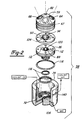
- pilot plasma guns 22 and 24 are of the conventional type in which a centrally disposed, rod-shaped cathode 26 is provided having a cone-shaped free end 28. Rod-shaped cathode 26 is secured in position by frictional engagement with retainer 30, one end of which is closed by closely fitting cap 32. As will be appreciated by those skilled in the art, cap 32 may be threaded onto retainer 30 such that rod-shaped cathode 26 can be replaced when worn. However, as will be more fully described hereinafter, in the present invention, the unique construction of the present invention may often reduce cathode wear so that replacement is less frequent.
- a ring of dielectric material such as, for example, a ceramic insulator 34 is provided to electrically isolate rod-shaped cathode 26 and its retaining structures from annular anode 36.
- Annular anode is secured in place by electrically insulating sheath 38 through which electrical lead 40 extends to make electrical contact with annular anode 36.
- electrical lead 42 extends through retainer 30 making electrical contact with rod-shaped cathode 26.
- Annular anode 36 is provided with nozzle opening 46 through which a pilot plasma is directed during start-up of plasma spray apparatus 20.
- rod-shaped cathode 26 will include internal passages through which a cooling medium such as water may be circulated to dissipate heat from rod-shaped cathode 26 developed during plasma operation.
- a similar heat exchange channel (not shown) is also preferably provided in annular anode 36 for the purpose of dissipating the extreme heat generated by the pilot plasma stream.
- Annular space 48 defined between the inner surface or wall of annular anode 36 and rod-shaped cathode 26 comprises a portion of a plasma gas passage which extends from plasma gas source 50 through a channel in insulating sheath 38 and retainer 30.
- retainer 30 inlcudes a portion which is spaced slightly from rod-shaped cathode 26 to permit the flow of plasma gas through a similar annular space provided by ceramic insulator 34 into annular space 48.
- high frequency oscillator 52 another high frequency oscillator 54 is provided in the electrical circuit for pilot plasma gun 22 which extends from cone-shaped end 28 of rod-shaped cathode 26 to annular anode 36.
- plasma gas as used herein shall be defined as any gas or mixture of gases which ionizes when passing through an electric arc of suitable electrical characteristics.
- a significant feature of the present invention is that it permits a final, coalesced free-standing plasma stream to be formed which includes an active or reactive gas such as, for example, oxygen without causing accelerated deterioration of rod-shaped cathode 26.
- an inert gas preferably argon
- suitable plasma gases will be known to those skilled in the art.
- Pilot plasma guns 22 and 24 are mounted in housing 58 at support block 59 such that they are displaced symmetrically about a common axis 60.
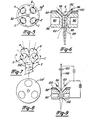
- plasma spray apparatus 20 be equipped with three pilot plasma guns in block 59′ as shown in Figure 8 or four plasma pilot guns in block 59 ⁇ as shown in Figure 5 of the drawings.
- the pilot plasma guns are symmetrically arranged about common axis 60 with each pilot plasma gun axes (62 and 62′ in Figure 1) intersecting at an included angle of preferably less than about 60 degrees.
- the included angle between axis 62 and axis 60 is preferably less than about 30 degrees as is the included angle between axis 62′ and axis 60.
- Bores 64 and 66 in block 59 closely receive, respectively, pilot plasma gun 24 and 22 in rigid engagement.
- block 59 in countersunk at bores 64 and 66 to provide a shoulder or rim on which insulating sheath 38 abuts.
- a dielectric ferrule 68 is provided as a sheath surrounding a portion of annular anode 36 to electrically insulate annular anode 36 from block 59.
- a polyester material is suitable for this purpose.
- Block 59 may be formed of any readily machinable metal such as, for example, brass. As shown in Figure 4, block 59 may be machined with four bores, two of which are plugged with plugs 65 and 67.
- block 59 can be easily adapted for 2 or 4 pilot plasma guns. It will also be understood that block 59 ⁇ shown in Figure 5 includes two additional bores for two additional pilot plasma guns (not shown). In this four-part configuration, each bore is spaced 90 degrees from each adjacent bore. In Figure 8, block 59′ is adapted to receive three pilot plasma guns spaced 120 degrees apart. In both arrangements, the bores are configured to support the pilot plasma guns angularly, preferably about 30 degrees or less off centre axis 60. This symmetry is important to provide a stable intersection of the pilot plasma streams.
- Block 59 is provided with annular heat exchange chamber 70 which is in flow communication with heat exchange passage 72 of jacket 74. In this manner, coolant 76 is flowed during operation through port 78 into heat exchange passage 72 whereby it is circulated through annular heat exchange chamber 70 to cool block 59. Where, as in the preferred embodiment, more than two pilot plasma guns are employed, additional bores may be provided symmetrically in block 59 as previously described.
- feedstock supply tube 80 is provided disposed in block 59 at bore 82.
- Feedstock supply tube 80 is closely received within bore 82 in frictional engagement with block 59.
- Feedstock supply tube 80 is open at its terminal end which extends into chamber 84 of block 59 and provides the means by which a feedstock material, such as, for example, a particular composition is delivered to the plasma along axis 60.
- a feedstock material such as, for example, a particular composition
- a solid feedstock in the form of a rod or the like may be suitable in some applications.
- pilot plasma guns 22 and 24 extend into chamber 84 at their nozzle opening ends.
- Housing 58 further includes main transfer anode 86 having a central bore or passage 88 extending the length thereof.
- Main transfer anode 86 is formed of an electrically conductive material such as, for example, copper and includes an annular channel 90 through which a coolant is circulated via heat exchange passage 72.
- annular channel 90 and heat exchange passage 72 are in flow communication.
- disc 92 is provided interposed between block 59 and main transfer anode 86. As will become apparent, this configuration permits easy fabrication and assembly.
- Disc 92 has a centrally disposed bore 94 which is concial in shape and which mates with main transfer anode 86 at a corresponding conical portion of bore 88.
- conical throat 96 is defined in which axis 62 and 62′ intersect.
- the included angle of conical throat 96 will typically be approximately 60 degrees or correspond to the angle of impingement of the pilot guns.
- Conical throat 96 and bore 88 are in axial alignment with axis 60.
- main transfer anode 86, disc 92, and block 59 are secured in position in jacket 74 with bolt 98.
- dielectric layer 100 serves to extend the length of main transferred plasma-arc or free-standing plasma 102 by preventing the contacting of the coalesced plasma stream until after it enters the bore of the main transfer anode.
- Main transfer anode is formed of a highly conductive material such as, for example, a copper alloy or the like.
- Disc 92 may be formed of a durable metal or a refractory oxide.
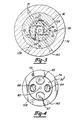
- annular gas channel 104 is shown adapted to receive a plasma-forming gas from plasma gas source 106 as illustrated in Fig.1. Referring to Figs.1, 2 and 3, plasma gas moves from gas source 106 through passage 108 which is a bore extending through jacket 74 of housing 58. In flow communication with passage 108, a second annular gas passage 110 is provided in jacket 74.
- Main transfer anode 86 also has a plurality of microbores 112 which are in flow communication with annular gas passage 110 and with annular gas channel 104.
- a plurality of tangential gas passages 114 are provided which facilitate the introduction of plasma gas from a secondary plasma gas source 106 into conical throat 96 in a spinning or whirling manner.
- a path of introduction more direct than that provided by the tangential geometry of gas passages 114 may be suitable, by flowing plasma gas into conical throat 96 in the preferred manner, the whirling motion of the plasma gas which is imparted creates a plasma vortex within passage 88. This vortex helps constrict free standing plasma 102 along with other factors, such that it is a highly-collimated stream.
- the gas manifold can be provided in a similar manner directly in main transfer anode 86.
- a plurality of O-rings 116 are also provided which conform to annular channels in the various structures of housing 58 such that substantially hermetic seals are attained.
- plasma spray apparatus 20 Numerous variations and modifications of plasma spray apparatus 20 will be apparent which are consistent with the principles of the present invention. For example, in most applications housing 58 will be encased in an electrically insulating material. Also, plasma spray apparatus 20 may be adapted to permit robotically-controlled spraying or hand-held spraying. Further, although plasma spray apparatus 20 is illustrated having two, three or four symmetrically disposed pilot plasma guns, five or more pilot plasma guns may be suitable or desirable in a particular application.
- plasma spray apparatus 20 is preferably utilized to apply a sprayed coating of a material such as, for example, a metal or ceramic to a target substrate.
- a material such as, for example, a metal or ceramic
- Other applications such as, for example, the processing of materials and the production of free-standing articles including near-net shapes are also preferred herein.
- Plasma spray apparatus 20 may also be suitable for use in high-temperature cutting or heating operations.
- rod-shaped cathode 26 of pilot plasma gun 24 is electrically connected to the negative terminal of an electrical power source 118 via lead 42.
- the rod-shaped cathode (not shown) of pilot plasma gun 22 is connected to the negative terminal of power source 118 with electrical lead 122.
- Annular anode 36 of pilot plasma gun 24 is electrically connected to the positive terminal of power source 123 via lead 40.
- Annular anode 124 of pilot plasma gun 22 is electrically connected to the positive terminal of power source 125 by lead 126. All power sources in the present invention preferably provide direct current.
- a first high frequency oscillator 52 and a second high frequency osciallator 54 are provided in the circuit for initiating an electric arc or "pilot arc" between each pilot plasma gun cathode and its respective annular anode. That is, high frequency oscillators 52 and 54 serve to initiate an electric arc between rod-shaped cathode 26 and annular anode 36 of pilot plasma gun 24 and, in pilot plasma gun 22, between annular anode 124 and its corresponding rod-shaped cathode (not shown).
- a first plasma gas such as, for example, argon
- plasma gas source 50 into annular space 48 and outwardly through nozzle opening 46 of pilot plasma gun 24.
- Plasma gas flow is initiated in pilot plasma gun 22 in the same manner.
- Switches 128 and 129 are then closed momentarily, activating high-frequency oscillators 52 and 54 and simultaneously connecting power sources 123 and 125 to pilot plasma guns 24 and 22, respectively, thereby initiating and establishing pilot arcs in the pilot plasma guns.
- a steady direct current maintains the electric arcs.
- plasma gas flows toward nozzle openings 46 and 130 of pilot plasma guns 24 and 22, respectively, preferably under pressure, it passes through the pilot arcs causing the plasma gas to ionize in the known manner.
- the plasma gas may be introduced axially or alternatively, "whirling" for form a vortex if desired.
- Non-transferred pilot plasma streams 56 and 132 are thus formed which intersect in conical throat 96 as shown also in Figs. 6 and 9.
- Switch 134 is then closed electrically energizing main transfer anode 86.
- the electromagnetic fields which are associated with charges in motion provide forces that affect the interaction of pilot plasma streams 56 and 132 at their point of intersection and the characteristics of free-standing plasma 102.
- main transfer anode 86 is energized, the electromagnetically coalescing pilot plasma streams 56 and 132 in conical throat 96 are drawn through conical throat 96 into the straight bore portion of passage 88. This occurs because the intersecting pilot plasma streams have the properties of a "flexible conductor" and thus generate electromagnetic fields which cause the plasmas to be attracted to one another, causing the plasmas to coalesce in conical throat 96.
- the intersecting streams are drawn toward the positive charge of main transfer anode 86 which is in electrical connection with power source 118 at its positive terminal via lead 136. (It will be noted that in this embodiment, jacket 74 is in electrical connection with main transfer anode 86. Other arrangements may be suitable.)
- the coalescing pilot plasma streams 56 and 132 move toward the exposed surfaces of main transfer anode 86 in the straight bore position of passage 88.
- Dielectric layer 100 prevents pilot plasma streams 56 and 132 from "short-circuiting" with main transfer anode 86 or disc 92 prior to electromagnetically coalescing.
- the electromagnetically coalesced plasma stream is extended into the straight bore portion of main transfer anode 86.
- the plasma voltage is increased, producing an increase in the plasma energy density. High plasma energy densities are desirable because they facilitate thermal energy transfer to the feedstock and increase particle velocities.
- a second or main plasma gas from plasma gas source 106 is flowed under pressure into conical throat 96 via passage 108, annular gas passage 110, microbores 112 and tangential gas passages 114, the latter of which, as stated, open into conical throat 96.
- an inert ionizable, plasma-forming gas be employed in forming pilot plasma streams 56 and 132 to prevent accelerated deterioration of the rod-shaped cathodes
- a significant advantage of the present invention is the ability to form a plasma stream which includes an active or "reactive" gas such as, for example, oxygen which is detrimental to the cathode material.
- an inert gas can be used in pilot plasma guns 22 and 24, thus protecting the rod-shaped cathodes, and an active gas then introduced downstream of the pilot plasma guns at conical throat 96.
- the use of a reactive gas may be desirable to alter the chemical composition of feedstock as it is sprayed and also permits higher operating voltages, since the latter is a function of the composition of the plasma gas.
- the tightly constricted free-standing plasma 102 makes electrical contact with main transfer anode 86 to complete the circuit. This occurs near plasma discharge opening 138 in passage 88 or at outer face 142 of main transfer anode 86.
- switches 128 and 129 of Figure 1 may be opened such that the annular anodes of the pilot plasma guns are disconnected from the circuit. Pilot plasma streams 56 and 132 continue to flow into conical throat 96 because they are electrically linked to main transfer anode 86 via free-standing plasma 102 which is maintained by a steady direct current.
- Pilot plasma streams 56 and 132 converge symmetrically at the intersection of axes 60, 62 and 62′, as shown in Figure 1. Pilot plasma streams 56 and 132 (and any additional pilot plasma streams where more than two symmetrically disposed pilot plasma guns are utilized) deflect uniformly at the point of intersection. The uniform deflection is brought about in part by the kinetic interacting forces of the intersecting plasmas and the symmetrical geometry. Further, each pilot plasma stream has an associated circumferential magnetic field, induced by the transferred DC electric current between each of the cathodes of the pilot plasma guns and the main transfer anode, illustrated by arrows A, B, C, and D in Figures 5 and 7.
- a magnetic field E is present which encircles the converging pilot plasma streams. Due to the superposition of the various magnetic vector components, magnetic field E serves to draw the individual plasma streams together as shown most clearly in Fig.7.
- the magnitude of this constricting magnetic pinch increases adjacent the point of intersection of the pilot plasma streams. This increasing magnetic pinch causes the individual pilot plasma streams to electromagnetically coalesce to form a stable coalesced plasma stream.
- the magnetic pinch increases the pressure, temperature and velocity of free- standing plasma 102. The magnitude of this magnetic pinch is proportional to the combined current conducted by the pilot plasma streams and free-standing plasma 102.
- a feedstock material is supplied to the point of intersection of the pilot plasmas.
- a particulate feedstock is injected through feedstock supply tube 80 which, as stated, is in axial alignment with axis 60. It is a significant advantage of the present invention that axial injection of feedstock can be achieved without disturbing the plasma arc. This is made possible by the angular arrangement of pilot plasma guns 22 and 24. The disadvantages of radial feed in prior art plasma spray apparatus are thus obviated by the present invention.
- the present invention provides uniform heating of the axially injected feedstock particles. Particle velocity is also extremely uniform. Supersonic particle velocities may be achieved.
- the feedstock will be injected under pressure through the use of an inert carrier gas.
- various operating parameters of plasma spray apparatus 20 including particle injection velocity, precise control over particle velocity and temperature can be achieved.
- feedstock enters the electromagnetically coalescing pilot plasma streams, it is entrained and accelerated in free-standing plasma 102 at its region of highest enthalpy.
- the heated, high-velocity particles are directed toward a target substrate which they impact to form a dense, uniform deposit. High deposition efficiencies are thereby achieved.
- Ceramics such as, for example, refractory oxides, metals and even polymers may be sprayed in this manner.
- One particularly preferred application is the fabrication of metal and ceramic matrix composites.
- the feedstock comprises rod 148 which is advanced by rollers 150 into the intersecting pilot plasma streams 56 and 132. Because pilot plasma streams 56 and 132 are electrically energized at their point of intersection, by applying an opposite electrical bias to rod 148, rod 148 becomes an electrode which may form an arc with the intersecting pilot plasmas. This electric feedstock arc and the heat generated by the intersecting pilot plasmas rapidly melts the tip of advancing rod 148. The molten feedstock is atomized by the intersecting pilot plasmas and moves into free-standing plasma 102 in the manner previously described.
- the flow rates of the plasma-forming gases into plasma spray apparatus as well as the injection velocity of feedstock may vary widely depending upon the desired temperatures, velocities and particle residence times.
Landscapes
- Physics & Mathematics (AREA)
- Engineering & Computer Science (AREA)
- Plasma & Fusion (AREA)
- Spectroscopy & Molecular Physics (AREA)
- Plasma Technology (AREA)
- Coating By Spraying Or Casting (AREA)
- Nozzles (AREA)
Applications Claiming Priority (2)
| Application Number | Priority Date | Filing Date | Title |
|---|---|---|---|
| US267145 | 1981-05-26 | ||
| US07/267,145 US4982067A (en) | 1988-11-04 | 1988-11-04 | Plasma generating apparatus and method |
Publications (2)
| Publication Number | Publication Date |
|---|---|
| EP0368547A1 true EP0368547A1 (fr) | 1990-05-16 |
| EP0368547B1 EP0368547B1 (fr) | 1996-08-28 |
Family
ID=23017511
Family Applications (1)
| Application Number | Title | Priority Date | Filing Date |
|---|---|---|---|
| EP89311290A Expired - Lifetime EP0368547B1 (fr) | 1988-11-04 | 1989-11-01 | Dispositif et procédé pour la production de plasma |
Country Status (5)
| Country | Link |
|---|---|
| US (1) | US4982067A (fr) |
| EP (1) | EP0368547B1 (fr) |
| JP (1) | JPH07107876B2 (fr) |
| CA (1) | CA1326886C (fr) |
| DE (1) | DE68927037D1 (fr) |
Cited By (9)
| Publication number | Priority date | Publication date | Assignee | Title |
|---|---|---|---|---|
| FR2678467A1 (fr) * | 1990-12-26 | 1992-12-31 | N Proizv Ob Tulatschermet | Procede de traitement au plasma de materiaux et dispositif pour sa realisation. |
| WO1996018283A1 (fr) * | 1994-12-05 | 1996-06-13 | The University Of British Columbia | Systeme de projection convergente de jets de plasma |
| WO1997018692A1 (fr) * | 1995-11-13 | 1997-05-22 | Ist Instant Surface Technology S.A. | Generateur de plasma a quatre buses pour la formation d'un jet active |
| EP0931176A4 (fr) * | 1996-09-30 | 2004-03-17 | Saint Gobain Norton Ind Cerami | Systeme ameliore de depot au jet de plasma |
| KR100493731B1 (ko) * | 2001-05-26 | 2005-06-03 | 한밭대학교 산학협력단 | 플라즈마 발생장치 |
| RU2267239C2 (ru) * | 2000-04-10 | 2005-12-27 | Тетроникс Лимитед | Устройство сдвоенной плазменной горелки |
| DE102007010996A1 (de) * | 2007-03-05 | 2008-09-11 | Arcoron Gmbh | Plasmadüse |
| RU2459010C2 (ru) * | 2006-11-28 | 2012-08-20 | Владимир Е. БЕЛАЩЕНКО | Плазменные устройство и система |
| CN109175639A (zh) * | 2018-10-30 | 2019-01-11 | 首都航天机械有限公司 | 一种同轴送丝双等离子弧增材制造装置 |
Families Citing this family (66)
| Publication number | Priority date | Publication date | Assignee | Title |
|---|---|---|---|---|
| US5052331A (en) * | 1989-10-18 | 1991-10-01 | The United States Of America As Represented By The United Sates Department Of Energy | Apparatus for gas-metal arc deposition |
| JPH03150341A (ja) * | 1989-11-07 | 1991-06-26 | Onoda Cement Co Ltd | 複合トーチ型プラズマ発生装置とその装置を用いたプラズマ発生方法 |
| US5256205A (en) * | 1990-05-09 | 1993-10-26 | Jet Process Corporation | Microwave plasma assisted supersonic gas jet deposition of thin film materials |
| US5356672A (en) * | 1990-05-09 | 1994-10-18 | Jet Process Corporation | Method for microwave plasma assisted supersonic gas jet deposition of thin films |
| CA2055897C (fr) * | 1990-11-21 | 1997-08-26 | Larry Sokol | Enceinte utilisee pour l'application d'un enduit vaporise a chaud et methode d'utilisation connexe |
| US5233153A (en) * | 1992-01-10 | 1993-08-03 | Edo Corporation | Method of plasma spraying of polymer compositions onto a target surface |
| RU2032280C1 (ru) * | 1992-02-18 | 1995-03-27 | Инженерный центр "Плазмодинамика" | Способ управления плазменным потоком и плазменное устройство |
| US6835523B1 (en) * | 1993-05-09 | 2004-12-28 | Semiconductor Energy Laboratory Co., Ltd. | Apparatus for fabricating coating and method of fabricating the coating |
| US5460701A (en) * | 1993-07-27 | 1995-10-24 | Nanophase Technologies Corporation | Method of making nanostructured materials |
| US5420391B1 (en) * | 1994-06-20 | 1998-06-09 | Metcon Services Ltd | Plasma torch with axial injection of feedstock |
| US5609921A (en) * | 1994-08-26 | 1997-03-11 | Universite De Sherbrooke | Suspension plasma spray |
| US5514848A (en) * | 1994-10-14 | 1996-05-07 | The University Of British Columbia | Plasma torch electrode structure |
| US5571332A (en) * | 1995-02-10 | 1996-11-05 | Jet Process Corporation | Electron jet vapor deposition system |
| US6447848B1 (en) | 1995-11-13 | 2002-09-10 | The United States Of America As Represented By The Secretary Of The Navy | Nanosize particle coatings made by thermally spraying solution precursor feedstocks |
| CN1195884C (zh) * | 1995-11-13 | 2005-04-06 | 康涅狄格大学 | 用于热喷涂的纳米结构的进料 |
| US5958521A (en) * | 1996-06-21 | 1999-09-28 | Ford Global Technologies, Inc. | Method of depositing a thermally sprayed coating that is graded between being machinable and being wear resistant |
| US6133577A (en) * | 1997-02-04 | 2000-10-17 | Advanced Energy Systems, Inc. | Method and apparatus for producing extreme ultra-violet light for use in photolithography |
| US6392190B1 (en) | 1998-01-23 | 2002-05-21 | Smith International | Automated hardfacing system |
| US6194733B1 (en) | 1998-04-03 | 2001-02-27 | Advanced Energy Systems, Inc. | Method and apparatus for adjustably supporting a light source for use in photolithography |
| US6105885A (en) * | 1998-04-03 | 2000-08-22 | Advanced Energy Systems, Inc. | Fluid nozzle system and method in an emitted energy system for photolithography |
| US6180952B1 (en) | 1998-04-03 | 2001-01-30 | Advanced Energy Systems, Inc. | Holder assembly system and method in an emitted energy system for photolithography |
| US6065203A (en) * | 1998-04-03 | 2000-05-23 | Advanced Energy Systems, Inc. | Method of manufacturing very small diameter deep passages |
| JP2003509223A (ja) * | 1999-09-21 | 2003-03-11 | ハイパーサーム インコーポレイテッド | 加工品を切断又は溶接するための方法及び装置 |
| US6423923B1 (en) | 2000-08-04 | 2002-07-23 | Tru-Si Technologies, Inc. | Monitoring and controlling separate plasma jets to achieve desired properties in a combined stream |
| US6962025B1 (en) | 2001-05-29 | 2005-11-08 | H.B. Fuller Licensing & Financing, Inc. | Metal plasma surface-modified thermal barrier channel |
| DE10140298B4 (de) * | 2001-08-16 | 2005-02-24 | Mtu Aero Engines Gmbh | Verfahren zum Plasmaschweißen |
| WO2004063416A2 (fr) * | 2003-01-10 | 2004-07-29 | Inframat Corporation | Appareil et procede de projection de solution pour plasma |
| DE10323014B4 (de) * | 2003-04-23 | 2007-11-22 | Fraunhofer-Gesellschaft zur Förderung der angewandten Forschung e.V. | Düse für Plasmabrenner |
| SG111177A1 (en) * | 2004-02-28 | 2005-05-30 | Wira Kurnia | Fine particle powder production |
| JP4449645B2 (ja) * | 2004-08-18 | 2010-04-14 | 島津工業有限会社 | プラズマ溶射装置 |
| FR2877015B1 (fr) * | 2004-10-21 | 2007-10-26 | Commissariat Energie Atomique | Revetement nanostructure et procede de revetement. |
| JP4604153B2 (ja) * | 2005-02-18 | 2010-12-22 | 国立大学法人東京海洋大学 | 防食性に優れた機能性被覆の形成法 |
| WO2006116844A1 (fr) * | 2005-05-02 | 2006-11-09 | National Research Council Of Canada | Procede et appareil destines a la suspension de particules fines dans un liquide, destines a un systeme d'aerosol thermique, et revetements formes au moyen de ces procede et appareil |
| US8859931B2 (en) * | 2006-03-08 | 2014-10-14 | Tekna Plasma Systems Inc. | Plasma synthesis of nanopowders |
| FR2900351B1 (fr) * | 2006-04-26 | 2008-06-13 | Commissariat Energie Atomique | Procede de preparation d'une couche nanoporeuse de nanoparticules et couche ainsi obtenue |
| DE102006044906A1 (de) * | 2006-09-22 | 2008-04-17 | Thermico Gmbh & Co. Kg | Plasmabrenner |
| US7411353B1 (en) * | 2007-05-11 | 2008-08-12 | Rutberg Alexander P | Alternating current multi-phase plasma gas generator with annular electrodes |
| DE102007041329B4 (de) | 2007-08-31 | 2016-06-30 | Thermico Gmbh & Co. Kg | Plasmabrenner mit axialer Pulvereindüsung |
| US7836843B2 (en) * | 2007-10-24 | 2010-11-23 | Sulzer Metco (Us), Inc. | Apparatus and method of improving mixing of axial injection in thermal spray guns |
| US8590804B2 (en) * | 2007-10-24 | 2013-11-26 | Sulzer Metco (Us) Inc. | Two stage kinetic energy spray device |
| US8849585B2 (en) * | 2008-06-26 | 2014-09-30 | Lam Research Corporation | Methods for automatically characterizing a plasma |
| WO2010005929A2 (fr) | 2008-07-07 | 2010-01-14 | Lam Research Corporation | Ensemble sonde électrostatique à couplage capacitif (cce) passive pour détecter des événements de formation d'arc électrique in situ dans une chambre de traitement au plasma |
| WO2010005932A2 (fr) * | 2008-07-07 | 2010-01-14 | Lam Research Corporation | Dispositif sonde regardant le plasma comportant un espace vide à utiliser dans une chambre de traitement au plasma |
| WO2010005934A2 (fr) * | 2008-07-07 | 2010-01-14 | Lam Research Corporation | Ensemble sonde électrostatique à couplage capacitif et à polarisation rf (rfb-cce) pour caractériser un film dans une chambre de traitement au plasma |
| US8164349B2 (en) | 2008-07-07 | 2012-04-24 | Lam Research Corporation | Capacitively-coupled electrostatic (CCE) probe arrangement for detecting strike step in a plasma processing chamber and methods thereof |
| TWI475592B (zh) | 2008-07-07 | 2015-03-01 | Lam Res Corp | 用來偵測電漿處理腔室中之電漿不穩定性的被動電容耦合靜電探針裝置 |
| TWI460439B (zh) * | 2008-07-07 | 2014-11-11 | 蘭姆研究公司 | 用來辨識電漿處理系統之處理腔室內的解除吸附情形之信號擾動特性的方法及裝置、及其電腦可讀儲存媒體 |
| US9997325B2 (en) * | 2008-07-17 | 2018-06-12 | Verity Instruments, Inc. | Electron beam exciter for use in chemical analysis in processing systems |
| US20100175926A1 (en) * | 2009-01-15 | 2010-07-15 | Baker Hughes Incorporated | Roller cones having non-integral cutting structures, drill bits including such cones, and methods of forming same |
| JP5414571B2 (ja) * | 2010-02-27 | 2014-02-12 | 日鐵住金溶接工業株式会社 | 移行式プラズマトーチ組体,プラズマ溶接装置およびプラズマ溶接方法 |
| US8492979B2 (en) * | 2010-03-25 | 2013-07-23 | General Electric Company | Plasma generation apparatus |
| TW201325326A (zh) * | 2011-10-05 | 2013-06-16 | 應用材料股份有限公司 | 電漿處理設備及其基板支撐組件 |
| US11783138B2 (en) | 2012-04-04 | 2023-10-10 | Hypertherm, Inc. | Configuring signal devices in thermal processing systems |
| US11432393B2 (en) | 2013-11-13 | 2022-08-30 | Hypertherm, Inc. | Cost effective cartridge for a plasma arc torch |
| US12275082B2 (en) | 2013-11-13 | 2025-04-15 | Hypertherm, Inc. | Consumable cartridge for a plasma arc cutting system |
| US10456855B2 (en) | 2013-11-13 | 2019-10-29 | Hypertherm, Inc. | Consumable cartridge for a plasma arc cutting system |
| US9981335B2 (en) | 2013-11-13 | 2018-05-29 | Hypertherm, Inc. | Consumable cartridge for a plasma arc cutting system |
| US11278983B2 (en) | 2013-11-13 | 2022-03-22 | Hypertherm, Inc. | Consumable cartridge for a plasma arc cutting system |
| US11684995B2 (en) | 2013-11-13 | 2023-06-27 | Hypertherm, Inc. | Cost effective cartridge for a plasma arc torch |
| US12521905B2 (en) | 2014-03-07 | 2026-01-13 | Hypertherm, Inc. | Liquid pressurization pump and systems with data storage |
| RU2693233C2 (ru) | 2014-08-12 | 2019-07-01 | Гипертерм, Инк. | Затратоэффективная головка для плазменно-дуговой горелки |
| JP2018523896A (ja) | 2015-08-04 | 2018-08-23 | ハイパーサーム インコーポレイテッド | 液冷プラズマアークトーチ用カートリッジ |
| MX2019009420A (es) | 2017-02-09 | 2019-10-02 | Hypertherm Inc | Anillo rotacional y elemento de contacto para un cartucho de antorcha de arco de plasma. |
| CN109041396A (zh) * | 2018-10-30 | 2018-12-18 | 广东省新材料研究所 | 一种双阴极轴向送料等离子喷枪 |
| CN114502597A (zh) * | 2019-10-11 | 2022-05-13 | 雷格努公司 | 共价固定分子化合物的方法 |
| US11654483B2 (en) * | 2020-04-07 | 2023-05-23 | General Electric Company | Method for forming high quality powder for an additive manufacturing process |
Citations (3)
| Publication number | Priority date | Publication date | Assignee | Title |
|---|---|---|---|---|
| US4009413A (en) * | 1975-02-27 | 1977-02-22 | Spectrametrics, Incorporated | Plasma jet device and method of operating same |
| WO1986002024A1 (fr) * | 1984-09-27 | 1986-04-10 | Regents Of The University Of Minnesota | Dispositif au plasma a arc multiple avec jet de gaz continu |
| US4630924A (en) * | 1985-07-29 | 1986-12-23 | The Dow Chemical Company | Conical DC plasma emission source |
Family Cites Families (17)
| Publication number | Priority date | Publication date | Assignee | Title |
|---|---|---|---|---|
| US2858411A (en) * | 1955-10-11 | 1958-10-28 | Union Carbide Corp | Arc torch and process |
| US2806124A (en) * | 1955-07-26 | 1957-09-10 | Union Carbide Corp | Arc torch and process |
| GB959472A (en) * | 1961-05-26 | 1964-06-03 | Her Majesty S Principal Sec De | Improvements in or relating to plasma jet torches |
| US3140380A (en) * | 1961-09-08 | 1964-07-07 | Avco Corp | Device for coating substrates |
| GB1199164A (en) * | 1966-10-01 | 1970-07-15 | Yamanouchi Pharma Co Ltd | Improved Process for the Preparation of Vitamin B12 Coenzyme and Derivatives thereof |
| US3770935A (en) * | 1970-12-25 | 1973-11-06 | Rikagaku Kenkyusho | Plasma jet generator |
| GB1449162A (en) * | 1973-05-25 | 1976-09-15 | Wellworthy Ltd | Method for reinforcing pistons |
| GB1493394A (en) * | 1974-06-07 | 1977-11-30 | Nat Res Dev | Plasma heater assembly |
| JPS517556A (en) * | 1974-07-08 | 1976-01-21 | Rikiichi Kimata | Keifunnadono mushiukikansoho |
| JPS5115119U (fr) * | 1974-07-22 | 1976-02-03 | ||
| US4386112A (en) * | 1981-11-02 | 1983-05-31 | United Technologies Corporation | Co-spray abrasive coating |
| US4818837A (en) * | 1984-09-27 | 1989-04-04 | Regents Of The University Of Minnesota | Multiple arc plasma device with continuous gas jet |
| USRE32908E (en) * | 1984-09-27 | 1989-04-18 | Regents Of The University Of Minnesota | Method of utilizing a plasma column |
| JPH0763034B2 (ja) * | 1984-11-10 | 1995-07-05 | 吉明 荒田 | 軸供給型プラズマ加熱材料噴射装置 |
| US4668852A (en) * | 1985-02-05 | 1987-05-26 | The Perkin-Elmer Corporation | Arc spray system |
| JPS61230300A (ja) * | 1985-04-05 | 1986-10-14 | プラズマ技研工業株式会社 | プラズマア−ク用ト−チ |
| US4689468A (en) * | 1986-02-10 | 1987-08-25 | Electro-Plasma, Inc. | Method of and apparatus providing oxide reduction in a plasma environment |
-
1988
- 1988-11-04 US US07/267,145 patent/US4982067A/en not_active Expired - Fee Related
-
1989
- 1989-09-27 CA CA000613402A patent/CA1326886C/fr not_active Expired - Fee Related
- 1989-11-01 EP EP89311290A patent/EP0368547B1/fr not_active Expired - Lifetime
- 1989-11-01 DE DE68927037T patent/DE68927037D1/de not_active Expired - Lifetime
- 1989-11-02 JP JP1285141A patent/JPH07107876B2/ja not_active Expired - Lifetime
Patent Citations (3)
| Publication number | Priority date | Publication date | Assignee | Title |
|---|---|---|---|---|
| US4009413A (en) * | 1975-02-27 | 1977-02-22 | Spectrametrics, Incorporated | Plasma jet device and method of operating same |
| WO1986002024A1 (fr) * | 1984-09-27 | 1986-04-10 | Regents Of The University Of Minnesota | Dispositif au plasma a arc multiple avec jet de gaz continu |
| US4630924A (en) * | 1985-07-29 | 1986-12-23 | The Dow Chemical Company | Conical DC plasma emission source |
Non-Patent Citations (1)
| Title |
|---|
| REVUE DE PHYSIQUE APPLIQUEE, vol. 12, no. 8, August 1977, pages 1127-1133, Paris, FR; F. KASSABJI: "Conditions d'amorçage de la superposition de puissance entre deux générateurs a plasma" * |
Cited By (10)
| Publication number | Priority date | Publication date | Assignee | Title |
|---|---|---|---|---|
| FR2678467A1 (fr) * | 1990-12-26 | 1992-12-31 | N Proizv Ob Tulatschermet | Procede de traitement au plasma de materiaux et dispositif pour sa realisation. |
| WO1996018283A1 (fr) * | 1994-12-05 | 1996-06-13 | The University Of British Columbia | Systeme de projection convergente de jets de plasma |
| WO1997018692A1 (fr) * | 1995-11-13 | 1997-05-22 | Ist Instant Surface Technology S.A. | Generateur de plasma a quatre buses pour la formation d'un jet active |
| US6278241B1 (en) * | 1995-11-13 | 2001-08-21 | Tepla Ag | Four-nozzle plasma generator for forming an activated jet |
| EP0931176A4 (fr) * | 1996-09-30 | 2004-03-17 | Saint Gobain Norton Ind Cerami | Systeme ameliore de depot au jet de plasma |
| RU2267239C2 (ru) * | 2000-04-10 | 2005-12-27 | Тетроникс Лимитед | Устройство сдвоенной плазменной горелки |
| KR100493731B1 (ko) * | 2001-05-26 | 2005-06-03 | 한밭대학교 산학협력단 | 플라즈마 발생장치 |
| RU2459010C2 (ru) * | 2006-11-28 | 2012-08-20 | Владимир Е. БЕЛАЩЕНКО | Плазменные устройство и система |
| DE102007010996A1 (de) * | 2007-03-05 | 2008-09-11 | Arcoron Gmbh | Plasmadüse |
| CN109175639A (zh) * | 2018-10-30 | 2019-01-11 | 首都航天机械有限公司 | 一种同轴送丝双等离子弧增材制造装置 |
Also Published As
| Publication number | Publication date |
|---|---|
| CA1326886C (fr) | 1994-02-08 |
| DE68927037D1 (de) | 1996-10-02 |
| EP0368547B1 (fr) | 1996-08-28 |
| JPH02236999A (ja) | 1990-09-19 |
| US4982067A (en) | 1991-01-01 |
| JPH07107876B2 (ja) | 1995-11-15 |
Similar Documents
| Publication | Publication Date | Title |
|---|---|---|
| US4982067A (en) | Plasma generating apparatus and method | |
| US5144110A (en) | Plasma spray gun and method of use | |
| CA1271229A (fr) | Methode et dispositif en rapport avec un chalumeau de chargement au plasma, avec reglage de l'apport radial et tangent du debit de gaz | |
| EP0775436B1 (fr) | Torche a plasma avec une alimentation par injection axiale | |
| EP0427194B1 (fr) | Dispositif du type torche multiple et méthode pour engendrer un plasma utilisant un tel dispositif | |
| US4841114A (en) | High-velocity controlled-temperature plasma spray method and apparatus | |
| US4916273A (en) | High-velocity controlled-temperature plasma spray method | |
| US4818837A (en) | Multiple arc plasma device with continuous gas jet | |
| US4540121A (en) | Highly concentrated supersonic material flame spray method and apparatus | |
| RU2569861C2 (ru) | Система термического плазменно-дугового проволочного напыления | |
| US5227603A (en) | Electric arc generating device having three electrodes | |
| CN112024885A (zh) | 一种等离子弧喷头及具有其的等离子发生装置和三维打印设备 | |
| EP0436576B1 (fr) | Dispositif generateur d'arc electrique | |
| JP3733461B2 (ja) | 複合トーチ型プラズマ発生方法及び装置 | |
| WO1986002024A1 (fr) | Dispositif au plasma a arc multiple avec jet de gaz continu | |
| GB2407050A (en) | Rotary ring cathode for plasma spraying | |
| RU2092981C1 (ru) | Плазмотрон для напыления порошковых материалов | |
| WO2006012165A2 (fr) | Appareil destine a generer un jet de plasma ainsi que procede d'utilisation associe | |
| US3472995A (en) | Electric arc torches | |
| US5743961A (en) | Thermal spray coating apparatus | |
| JPH05339699A (ja) | プラズマ溶射方法 | |
| EP3742869A1 (fr) | Torche à plasma miniaturisée | |
| CA1262758A (fr) | Torche au plasma a convergence d'anode et de gaz turbulent dans sa buse pour contraindre | |
| AU620455B2 (en) | Electric arc generating device | |
| JPH04333556A (ja) | クロミヤの溶射方法 |
Legal Events
| Date | Code | Title | Description |
|---|---|---|---|
| PUAI | Public reference made under article 153(3) epc to a published international application that has entered the european phase |
Free format text: ORIGINAL CODE: 0009012 |
|
| AK | Designated contracting states |
Kind code of ref document: A1 Designated state(s): BE CH DE ES FR GB IT LI NL SE |
|
| 17P | Request for examination filed |
Effective date: 19900927 |
|
| 17Q | First examination report despatched |
Effective date: 19921217 |
|
| GRAH | Despatch of communication of intention to grant a patent |
Free format text: ORIGINAL CODE: EPIDOS IGRA |
|
| GRAH | Despatch of communication of intention to grant a patent |
Free format text: ORIGINAL CODE: EPIDOS IGRA |
|
| GRAA | (expected) grant |
Free format text: ORIGINAL CODE: 0009210 |
|
| AK | Designated contracting states |
Kind code of ref document: B1 Designated state(s): BE CH DE ES FR GB IT LI NL SE |
|
| PG25 | Lapsed in a contracting state [announced via postgrant information from national office to epo] |
Ref country code: NL Free format text: LAPSE BECAUSE OF FAILURE TO SUBMIT A TRANSLATION OF THE DESCRIPTION OR TO PAY THE FEE WITHIN THE PRESCRIBED TIME-LIMIT Effective date: 19960828 Ref country code: BE Effective date: 19960828 Ref country code: IT Free format text: LAPSE BECAUSE OF FAILURE TO SUBMIT A TRANSLATION OF THE DESCRIPTION OR TO PAY THE FEE WITHIN THE PRESCRIBED TIME-LIMIT;WARNING: LAPSES OF ITALIAN PATENTS WITH EFFECTIVE DATE BEFORE 2007 MAY HAVE OCCURRED AT ANY TIME BEFORE 2007. THE CORRECT EFFECTIVE DATE MAY BE DIFFERENT FROM THE ONE RECORDED. Effective date: 19960828 Ref country code: FR Effective date: 19960828 Ref country code: ES Free format text: THE PATENT HAS BEEN ANNULLED BY A DECISION OF A NATIONAL AUTHORITY Effective date: 19960828 |
|
| REG | Reference to a national code |
Ref country code: CH Ref legal event code: NV Representative=s name: ISLER & PEDRAZZINI AG |
|
| REF | Corresponds to: |
Ref document number: 68927037 Country of ref document: DE Date of ref document: 19961002 |
|
| PG25 | Lapsed in a contracting state [announced via postgrant information from national office to epo] |
Ref country code: SE Effective date: 19961128 |
|
| PG25 | Lapsed in a contracting state [announced via postgrant information from national office to epo] |
Ref country code: DE Effective date: 19961129 |
|
| EN | Fr: translation not filed | ||
| NLV1 | Nl: lapsed or annulled due to failure to fulfill the requirements of art. 29p and 29m of the patents act | ||
| PLBE | No opposition filed within time limit |
Free format text: ORIGINAL CODE: 0009261 |
|
| STAA | Information on the status of an ep patent application or granted ep patent |
Free format text: STATUS: NO OPPOSITION FILED WITHIN TIME LIMIT |
|
| 26N | No opposition filed | ||
| PGFP | Annual fee paid to national office [announced via postgrant information from national office to epo] |
Ref country code: GB Payment date: 19991027 Year of fee payment: 11 |
|
| PGFP | Annual fee paid to national office [announced via postgrant information from national office to epo] |
Ref country code: CH Payment date: 19991111 Year of fee payment: 11 |
|
| PG25 | Lapsed in a contracting state [announced via postgrant information from national office to epo] |
Ref country code: GB Free format text: LAPSE BECAUSE OF NON-PAYMENT OF DUE FEES Effective date: 20001101 |
|
| PG25 | Lapsed in a contracting state [announced via postgrant information from national office to epo] |
Ref country code: LI Free format text: LAPSE BECAUSE OF NON-PAYMENT OF DUE FEES Effective date: 20001130 Ref country code: CH Free format text: LAPSE BECAUSE OF NON-PAYMENT OF DUE FEES Effective date: 20001130 |
|
| GBPC | Gb: european patent ceased through non-payment of renewal fee |
Effective date: 20001101 |
|
| REG | Reference to a national code |
Ref country code: CH Ref legal event code: PL |