EP0368760A2 - Autonomer Detektor für Fehler in einem elektrischen Netz und dazugehöriges Verfahren - Google Patents
Autonomer Detektor für Fehler in einem elektrischen Netz und dazugehöriges Verfahren Download PDFInfo
- Publication number
- EP0368760A2 EP0368760A2 EP89403087A EP89403087A EP0368760A2 EP 0368760 A2 EP0368760 A2 EP 0368760A2 EP 89403087 A EP89403087 A EP 89403087A EP 89403087 A EP89403087 A EP 89403087A EP 0368760 A2 EP0368760 A2 EP 0368760A2
- Authority
- EP
- European Patent Office
- Prior art keywords
- control
- fault
- detection
- duration
- processing
- Prior art date
- Legal status (The legal status is an assumption and is not a legal conclusion. Google has not performed a legal analysis and makes no representation as to the accuracy of the status listed.)
- Withdrawn
Links
- 238000000034 method Methods 0.000 title claims description 14
- 230000008569 process Effects 0.000 title description 3
- 238000012545 processing Methods 0.000 claims abstract description 75
- 238000001514 detection method Methods 0.000 claims abstract description 68
- 238000004458 analytical method Methods 0.000 claims abstract description 35
- 238000012544 monitoring process Methods 0.000 claims abstract description 8
- 230000008034 disappearance Effects 0.000 claims abstract description 5
- 238000012546 transfer Methods 0.000 claims description 10
- 230000007547 defect Effects 0.000 claims description 6
- 238000004146 energy storage Methods 0.000 claims description 5
- 230000001186 cumulative effect Effects 0.000 claims description 3
- 230000004913 activation Effects 0.000 claims description 2
- 230000015654 memory Effects 0.000 description 34
- 238000010586 diagram Methods 0.000 description 7
- 238000005259 measurement Methods 0.000 description 7
- 238000012360 testing method Methods 0.000 description 5
- 230000006870 function Effects 0.000 description 4
- 238000005265 energy consumption Methods 0.000 description 3
- 238000011084 recovery Methods 0.000 description 3
- 230000008859 change Effects 0.000 description 2
- 238000006243 chemical reaction Methods 0.000 description 2
- 230000000694 effects Effects 0.000 description 2
- 239000004973 liquid crystal related substance Substances 0.000 description 2
- 238000012423 maintenance Methods 0.000 description 2
- 208000032368 Device malfunction Diseases 0.000 description 1
- 235000014676 Phragmites communis Nutrition 0.000 description 1
- 230000005540 biological transmission Effects 0.000 description 1
- 230000001143 conditioned effect Effects 0.000 description 1
- 230000008878 coupling Effects 0.000 description 1
- 238000010168 coupling process Methods 0.000 description 1
- 238000005859 coupling reaction Methods 0.000 description 1
- 230000009849 deactivation Effects 0.000 description 1
- 235000013305 food Nutrition 0.000 description 1
- 238000010438 heat treatment Methods 0.000 description 1
- 238000007689 inspection Methods 0.000 description 1
- 238000009413 insulation Methods 0.000 description 1
- 230000007774 longterm Effects 0.000 description 1
- 230000014759 maintenance of location Effects 0.000 description 1
- 239000000463 material Substances 0.000 description 1
- 238000012986 modification Methods 0.000 description 1
- 230000004048 modification Effects 0.000 description 1
- 238000007639 printing Methods 0.000 description 1
- 230000002035 prolonged effect Effects 0.000 description 1
- 239000010453 quartz Substances 0.000 description 1
- 239000000523 sample Substances 0.000 description 1
- VYPSYNLAJGMNEJ-UHFFFAOYSA-N silicon dioxide Inorganic materials O=[Si]=O VYPSYNLAJGMNEJ-UHFFFAOYSA-N 0.000 description 1
Images



Classifications
-
- G—PHYSICS
- G01—MEASURING; TESTING
- G01R—MEASURING ELECTRIC VARIABLES; MEASURING MAGNETIC VARIABLES
- G01R13/00—Arrangements for displaying electric variables or waveforms
- G01R13/04—Arrangements for displaying electric variables or waveforms for producing permanent records
- G01R13/06—Modifications for recording transient disturbances, e.g. by starting or accelerating a recording medium
Definitions
- the present invention relates to an autonomous device for detecting faults on an electrical network. It also relates to the method for detecting these faults, in particular by means of the aforementioned device.
- the energy distribution services do not always succeed in identifying the voltage discontinuities occurring on their network and cannot therefore compensate for these faults.
- a system for recording and collecting measurements comprises, at several measurement points, a device comprising at least one measurement sensor, an interface block ensuring conversion and / or multiplexing, a local memory and a clock associated with a sequencer to excite the sensor and control the block interface and memory.
- the measurement results, recorded in the local memories of the various devices are collected periodically in a collection memory capable of being connected to each local memory and being brought to centralized measurement processing means.
- the measurement instants are fixed by the clock and it is therefore not possible to detect a fault which can obviously occur at any time.
- one or more physical quantities are converted, possibly multiplexed and then stored in the local memory. Such a system therefore does not allow storage exclusive of data concerning faults detected on an electrical network.
- a line voltage monitoring system is in the form of two independent functional blocks, a detection unit and a printing unit, which can be connected by a serial link.
- the acquisition of the mains voltage and its comparison with collapse and overvoltage thresholds is carried out only at predetermined instants which are the instants of the beginning of each half-cycle of the sector.
- the fault durations measured are necessarily integral multiples of the electrical half-period of the sector analyzed.
- a voltage zero crossing detection circuit provides the necessary synchronization signal.
- the network fault detection unit includes a microprocessor, an EPROM read-only memory, a RAM memory and a clock circuit. It also includes an analog / digital converter, pulse and common mode half cycle detectors, and a counter.
- the energy required to supply the unit is taken directly from the sector analyzed and is converted into direct voltage. Only the RAM memory and the clock circuit are supplied by a battery in the event of prolonged collapse of the mains voltage.
- the object of the present invention is to remedy these drawbacks by proposing an autonomous device for detection of faults on an electrical network, comprising: means for detecting the presence of faults on the electrical network and delivering detection information, connected to said electrical network by connection terminals, control and processing means connected to said detection means for processing said detection information and generating fault analysis data, - permanent storage means connected to said control and processing means for storing said analysis data, and autonomous means for storing and supplying energy for all or part of the aforementioned means.
- this device is characterized in that the detection means further detect the instants of appearance and disappearance of the faults and in that the control and treatment means determine the respective duration of each of said faults.
- the detection means make it possible to obtain the duration of a defect by knowing the instants of appearance and disappearance of this defect. This duration information is of great importance when it comes to studying service discontinuities on a network. A statistical study can then be carried out in order to locate and identify the causes of discontinuity.
- the device further comprises means for controlling the supply of energy by the autonomous means of storage and supply of energy to the control and processing means according to the possible detection. faults by said means of detection and requests for activation of said control and processing means external to said device.
- control means make it possible to guarantee a high autonomy of the device according to the invention insofar as the control and processing means are supplied and therefore activated in practice only when a fault appears or that an operator external to said device wishes access fault analysis data.
- the source of autonomy of energy which can be a cell or a battery sees its lifespan lengthened.
- This arrangement allows the supply of power to the control and processing means to be maintained beyond the duration of the fault and thus the analysis and storage of the data.
- the control and processing means are then put out of service to limit the energy consumption of the device.
- control and processing means include counting means for substantially determining the duration of a possible fault from the information delivered by the detection means, and means for associating for each period of duration belonging to a set of predetermined periods of duration, a number equal to the number of detected faults, the duration of which is substantially included in said period of time, these numbers of faults per period of period being updated by the control and processing means during each detection and stored in said permanent storage means.
- This provides an initial analysis of the discontinuities at a point on the network; this analysis can provide valuable information on the repetition of a fault and on the possible cause of certain faults depending on their duration.
- the device further comprises clock means connected to the control and processing means, to provide the latter, upon each detection and treatment of a fault, with date and time information of the start of the fault, and these clock means are supplied with energy permanently by the energy storage and supply means.
- fault records including the date, time and duration of the faults.
- These recordings with history can then be used, in particular by comparison between recordings made on separate devices placed at several points on an electrical network.
- the method for detecting and analyzing faults on an electrical network comprises a step of detecting the presence of a fault on the network electric by means of fault detection, followed by a step of analyzing this fault by means of control and processing and by a step of storing the analysis results obtained in the previous step in means of permanent storage.
- This method is characterized in that the analysis step is initiated by the appearance of the fault itself and in that, during this step, the duration of the fault is substantially determined by the control and processing means.
- the autonomous detection device stores faults on the electrical network by time slots and can be represented in principle by the block diagram of FIG. 1.
- a capture module 1 loaded monitoring a setpoint, for example voltage or current. This module works in all or nothing and transmits its state by the commissioning of a relay.
- Module 1 draws its energy from the setpoint to be monitored or directly from another part of the device. It also has a tilting threshold adjustment system in stages.
- the capture module 1 is connected to a processing module 2 which preferably includes a microcontroller.
- the processing module 2 has in particular the functions of counting the cut-off times and of discriminating between several cut-off sections. The different types of processing provided by the processing module 2 will be described during the detailed explanation of the operation of the device.
- the processing module requires, on the one hand, to be supplied by a supply module 5, and on the other hand, to be associated with a storage memory 3.
- the components of the device according to the invention are all chosen so that the overall energy consumption of the device is minimized. Furthermore, as will be explained below, the operating mode chosen also contributes to limiting energy consumption.
- the power supply module 5 can include as a power source a conventional battery which powers a voltage regulator. Given the low consumption of the treatment module, an autonomy of one year is possible.
- the non-volatile storage memory 3 guarantees security of retention of the data processed in the event of temporary device malfunction.
- the result of the fault treatment is displayed thanks to a display and control module 4 connected to the processing module 2.
- the display module preferably includes an 8-digit liquid crystal display.
- the very low consumption of this type of display allows it to be powered by the power supply module 5.
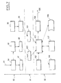
- the device according to the invention provides a recording of faults with history (date, time, duration). It is represented in the form of a block diagram in FIG. 2.
- the device includes a clock module 7 connected to the processing module 9, non-volatile site memories 10 and data 11, and an exchange converter module 12 connected to the processing module 9.
- the clock module 5 preferably consists of a specialized integrated circuit provided with a quartz. It provides the temporary references necessary for registration. Its management is carried out by the processing module 9.
- the module 5 also has an alarm system which enables the device to be reactivated in the event of long-term incidents and is powered by the power supply module 8.
- the exchange converter module 12 converts electrical levels of signals emitted by the device in order to make them compatible with a portable input terminal 13 which can be temporarily connected to the device for transferring the data recorded in memory.
- the converter module 12 can be summarized as a simple connector followed by protection circuits. It can also be made up of infrared or ultrasonic transceiver circuits. If a high level of mechanical protection is required, the use of electromagnetic coupling is advisable.
- the portable input terminal 13 has preferably a display system, an autonomous power supply and sufficient storage memory.
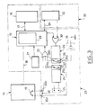
- the autonomous fault detection device on an electrical network comprises, in a particular embodiment, with reference to FIG. 3, a fault detection and analysis part 33, and a clock part 32, these components cooperating to ensure the network quality of service analysis function with historical outage recording.
- the detection and analysis part 33 comprises means 26 for detecting a cut in the sector applied to the connection terminals 25, which control a relay 27, control and processing means 15, for example a microcontroller, means for non-volatile storage 16 connected to said control and processing means 15.
- a battery 31 or any other device capable of storing energy and of restoring it in the form of a DC voltage.
- This battery supplies the microcontroller only when a fault has been detected by the detection means 26 or when an input terminal 14 is connected to the detection and analysis device via the connection terminals 20 and d 'A serial link 18. This connection causes the terminals 20 to short-circuit by means of a strap 19.
- An OR logic gate 22 controls the supply of the microcontroller 15 and its three inputs are respectively connected to one of the connection terminals 20b, to one of the contacts of the relay 27b and to one of the contacts of a relay 28b of self-maintenance.
- the other three contacts 20a, 27a and 28a are connected together to the voltage source 31.
- OR logic function of gate 22 ensures that if at least one of the three points 20b, 27b, 28b is subjected to the reference voltage, the microcontroller is then supplied.
- the self-sustaining relay 28 is controlled by control means 29 themselves piloted by an OR logic gate 30 with two inputs connected respectively to an output line of the microprocessor 15 and to an output line of the clock 52 which is also connected to the microcontroller 15 by a serial link specialized 24.
- a battery test circuit 21 is also connected to the microcontroller 15.
- the cut-off detection means 26 may for example comprise a network of resistors and a diode bridge connected to the relay 27, for example a reed relay closed at rest.
- the coil / contact insulation voltage is 4 kv.
- Relay 27 is almost always supplied. In order to reduce its heating, a fairly low operating voltage, of the order of 5 v, was chosen.
- the supply resistors are oversized in power. The heat given off by these resistors, provided that the housing is relatively sealed, maintains a constant temperature, thus making it possible to use components of standard range.
- the control and processing means 15 preferably comprise a microcontroller of the INTEL 8051 type provided with an internal program memory 23.
- the autonomous fault detection device is installed in the immediate vicinity of the point studied on the electrical network.
- the device according to the invention is included in a box, which can for example be made of plastic material and of which the front face is protected in normal use by a hinged cover 35 closed with a sealable screw 36.
- the front face comprises a switch 37 for adjusting the tilting threshold of the capture module 1 (FIG. 1), liquid crystal displays 38, a battery 39, for example of 9v, connection terminals 42 to the electrical network, a push button 40 for resetting the memory 3 to zero and a push button 41 for display control.
- the second preferred embodiment of the device according to the invention is shown in a practical configuration in FIG. 5.
- the autonomous detection device is included in a housing 43, the rear face of which has three recesses 44, 45, 46 for fixing the housing to a wall.
- the front face of the housing has an opening providing access to the input / output components of the device and to the supply battery 47. This opening is, in ordinary times, masked by a leaded inspection hatch 51.
- the accessible components of the device are a setpoint adjustment switch 48, connection terminals 49, the supply battery 47 and a connector 50 allowing the transfer of the stored data to displays or to a portable input terminal.
- the first type of processing carried out is the control of a duration counter internal to the microcontroller 15.
- the duration counter is put into service when a fault occurs on the network and is stopped when there is restoration of the instructions. It is calibrated in units compatible with the phenomena to be analyzed, for example, tenths of seconds for a network fault analyzer. The fault and recovery conditions are deduced from the state of a port of the microcontroller 15.
- the device controls its own power supply.
- the power-up is caused by an external phenomenon such as a fault or a display request. Then there is self-maintenance of the food until the incident phenomenon has been completely treated.
- the microcontroller 15 then controls the disconnection of the power supply via the relay 28, with reference to FIG. 3.
- the microcontroller 15 also ensures the determination of the slot number concerned by the fault which has just been detected and the duration of which has been measured.
- the microcontroller 15 ensures that the duration of the fault is indeed within the minimum authorized range. Then it scans the predefined slice table in memory and assigns a slice number to the default. In the event that the duration of the fault is not within the minimum authorized section, the microcontroller 15 disconnects without any particular treatment.
- microcontroller 15 Another processing devolved to the microcontroller 15 is the management of the data memory 16 as well as the transcoding of the data. These are indeed stored in hexadecimal form in order to occupy less space. On the other hand, to facilitate the reading of the data by an operator, the microcontroller 15 performs their conversion in decimal form.
- the microcontroller 15 also controls the power supply in cooperation with the battery test circuit 21.
- the latter includes a comparator with reference voltage by Zener diode which informs the microcontroller 15 on the activity of the battery.
- the state of the battery 39 is transmitted to the displays 38, with reference to FIG. 4, at the start of the display request cycle. In the case of an out of tolerance battery, its replacement is requested and if this is not done, the program is blocked in this state.
- two push-buttons are presented, one 41 for scrolling the display on the displays 38, the other 40 for erasing the memory.
- Other functions, obtained by combining the two pushbuttons, could be envisaged, for example, modifying the table for defining the time slots.
- the microcontroller analyzes the state of the push buttons 40, 41 and undertakes the corresponding processing. It also processes rebounds to ensure the validity of an order.
- a fault characterized by a voltage drop
- the electrical network to which the device according to the invention is connected step 60
- the contacts 27a, 27b normally open, are then closed due to the de-excitation of the relay 27 (step 61).
- Closing the contacts 27a, 27b then causes the microcontroller 15 to be powered by the battery 31 via the OR logic gate 22 (step 62).
- the powering of the microcontroller leads to an initialization (RESET) of the latter (step 63) which then undertakes the execution of a firmware written in its internal memory 23.
- RESET initialization
- a first operation consists for him in transmitting a self-sustaining order intended for the control means 29 of the self-sustaining relay 28, via the OR logic gate 30 (step 64).
- the initialization of the internal duration counter is then carried out (step 65), its initial count value being fixed at zero (step 66) and its launching is controlled (step 67).
- the counter remains active (sequence 85) as long as a recovery detection signal is not not received by the microcontroller 15. This latter probe periodically has an input port (step 68).
- the counter is stopped (step 69) and the discrimination by time slots is then undertaken. In the example described here, ten time slots are provided.
- a first test 70 makes it possible to identify a duration less than the minimum duration. If this identification takes place, step 83 of removing the self-sustaining power supply is directly performed, followed by step 84 of stopping the treatment.
- the duration of the fault, materialized by the content of the counter is successively compared with at most 9 values of increasing slice limit values, preferably regularly distributed, during tests 71 to 79, until the one of the tests determines the range in which the fault must be indexed.
- Step 80 corresponds to the case of the upper tranche which includes defects of duration greater than a predetermined duration.
- a step 81 of incrementing the slice counter is then carried out.
- an event counter internal to the microcontroller updates the section affected by the fault by incrementing a cumulative variable of the number of faults at any time, in non-volatile memory, the number of faults associated with this section (step 82). There are faults detected for each period of time.
- the microcontroller 15 commands the removal of its own power supply by sending a deactivation order of the self-sustaining relay 28 by the control means 28, via the OR logic gate 30 (step 83). Cutting off the power to the microcontroller naturally stops the treatment (step 84).
- steps 60 to 69 described for the operation of the device with time slots, remain valid.
- steps 70 to 82 of discrimination by sections are replaced by a step of recording the history of the current fault (date, time, duration, site) carried out by means of clock 32 and the memory of non-volatile storage 16, with reference to FIG. 3.
- the data stored in the memory 16 are transferred outside the device for further processing as follows: an operator provided with a portable input terminal 14 accesses the front face of the device by removing the plate 51 from the housing 43 , with reference to Figure 5.
- This short-circuiting has the effect of energizing the microcontroller 15 via the OR logic gate 22.
- the microcontroller 15 will remain supplied as long as the portable input terminal 14 is connected to the detection and analysis part 33 of the device according to the invention.
- the autonomous detection device with historical recording comprises a system for limiting the duration of supply of the microcontroller 15.
- the power to the microcontroller 15 is cut.
- the clock 52 sends an alarm signal which powers the microcontroller.
- the microcontroller 15 checks whether there is recovery. If not, it couples the supply and waits for another alarm cycle.
- the microcontroller 15 is also responsible for controlling exchanges with the portable input terminal 14 and makes it possible to adapt to the specific protocol of this terminal (detection of handshake signals, recognition of keywords, transfer speed).
- the microcontroller 15 recognizes the V24 serial protocol.
- the memory 16 is functionally divided into two spaces: - data memory, - the memory of site parameters.
- each record consists of the date and time of the start of the incident followed by its duration.
- the recording is sequential and the recording of a memory box is carried out only once between two readings.
- site-specific parameters are saved, such as, for example, the device number, geographic location, functional location. These parameters are read by the portable input terminal 14 so that the processing system, to which the transferred data are ultimately intended, can identify the source of these data.
- This memory space can also contain the value of the switching setpoint and can be updated, for example, from the portable input terminal 14. For security reasons, its access will preferably be conditioned by the use of a password.
- the integrated quality of service analysis system follows the tree structure of the electrical distribution network shown in the block diagram in Figure 7.
- a collection phase 90 It has three phases: a collection phase 90, a transfer phase 91 and an operation phase 92.
- Autonomous detection devices in accordance with the invention are placed at each network node, at the high voltage / medium voltage (HV / LV) transformer substations. ) 94, and medium voltage / low voltage (MV / LV) 98 and possibly on certain network end points, such as subscriber counters.
- HV / LV high voltage / medium voltage
- MV / LV medium voltage / low voltage
- the autonomous detection devices 97, 98 memorize the duration and the date of each incident and are each coded according to its location.
- the operator of the distribution network collects the information stored in the autonomous detection devices 97, 98, by means of portable input terminals 100 which can also be used for other applications.
- All the information collected by the portable input terminals 100 is processed by a computer processing station 103 with which is associated a data acquisition module 106, a correspondence table 102, a data processing module 107, preferably a personal microcomputer, an editing module 108 and a modem 104 allowing exchanges of information between the computer processing station 103 and central computers via a telephone line 105.
- a computer processing station 103 with which is associated a data acquisition module 106, a correspondence table 102, a data processing module 107, preferably a personal microcomputer, an editing module 108 and a modem 104 allowing exchanges of information between the computer processing station 103 and central computers via a telephone line 105.
- each portable input terminal 100 is equipped with communication software allowing dialogue on the one hand with the autonomous detection devices 97, 98 and, on the other hand, with the computer processing station 103.
- the operator 96 records the information from each autonomous detection device and reports the incidents observed visually using an incident form 99. It then transfers the information recorded on these forms to the processing station computer 103 by means of the keyboard 101.
- the electrical technical services give reports of controls carried out in the field and these reports are also provided to the computer processing station 103.
Landscapes
- Physics & Mathematics (AREA)
- General Physics & Mathematics (AREA)
- Debugging And Monitoring (AREA)
- Remote Monitoring And Control Of Power-Distribution Networks (AREA)
- Supply And Distribution Of Alternating Current (AREA)
- Investigating Or Analysing Biological Materials (AREA)
- Monitoring And Testing Of Transmission In General (AREA)
- Arrangements For Transmission Of Measured Signals (AREA)
- Testing Electric Properties And Detecting Electric Faults (AREA)
- Charge And Discharge Circuits For Batteries Or The Like (AREA)
Applications Claiming Priority (2)
| Application Number | Priority Date | Filing Date | Title |
|---|---|---|---|
| FR8814626A FR2638850B1 (fr) | 1988-11-09 | 1988-11-09 | Dispositif autonome de detection de defauts sur un reseau electrique et procede s'y rapportant |
| FR8814626 | 1988-11-09 |
Publications (2)
| Publication Number | Publication Date |
|---|---|
| EP0368760A2 true EP0368760A2 (de) | 1990-05-16 |
| EP0368760A3 EP0368760A3 (de) | 1990-05-23 |
Family
ID=9371716
Family Applications (1)
| Application Number | Title | Priority Date | Filing Date |
|---|---|---|---|
| EP89403087A Withdrawn EP0368760A3 (de) | 1988-11-09 | 1989-11-08 | Autonomer Detektor für Fehler in einem elektrischen Netz und dazugehöriges Verfahren |
Country Status (10)
| Country | Link |
|---|---|
| EP (1) | EP0368760A3 (de) |
| AU (1) | AU633524B2 (de) |
| CA (1) | CA2002471A1 (de) |
| DE (1) | DE368760T1 (de) |
| DK (1) | DK557589A (de) |
| ES (1) | ES2017600A4 (de) |
| FR (1) | FR2638850B1 (de) |
| GR (1) | GR900300176T1 (de) |
| NO (1) | NO894387L (de) |
| NZ (1) | NZ231306A (de) |
Families Citing this family (1)
| Publication number | Priority date | Publication date | Assignee | Title |
|---|---|---|---|---|
| AU660302B2 (en) * | 1991-04-04 | 1995-06-22 | Anthony Joseph Griffin | Control scheme for differential protection of electric railway feeder circuit breakers |
Family Cites Families (5)
| Publication number | Priority date | Publication date | Assignee | Title |
|---|---|---|---|---|
| US3813667A (en) * | 1973-05-29 | 1974-05-28 | Us Navy | Three-phase power disturbance monitor |
| US3846698A (en) * | 1973-09-25 | 1974-11-05 | Westinghouse Electric Corp | Overcurrent events monitoring system |
| IT1119341B (it) * | 1979-08-02 | 1986-03-10 | Cselt Centro Studi Lab Telecom | Analizzatore di tensioni impulsive |
| US4558275A (en) * | 1981-04-21 | 1985-12-10 | The Superior Electric Company | Line voltage monitor system |
| FR2571500B1 (fr) * | 1984-10-05 | 1986-12-19 | Commissariat Energie Atomique | Ensemble electronique de detection des variations fugitives d'une tension electrique en fonction du temps |
-
1988
- 1988-11-09 FR FR8814626A patent/FR2638850B1/fr not_active Expired - Lifetime
-
1989
- 1989-11-03 NO NO89894387A patent/NO894387L/no unknown
- 1989-11-07 NZ NZ23130689A patent/NZ231306A/en unknown
- 1989-11-08 DE DE1989403087 patent/DE368760T1/de active Pending
- 1989-11-08 DK DK557589A patent/DK557589A/da not_active Application Discontinuation
- 1989-11-08 EP EP89403087A patent/EP0368760A3/de not_active Withdrawn
- 1989-11-08 ES ES89403087T patent/ES2017600A4/es active Pending
- 1989-11-08 CA CA 2002471 patent/CA2002471A1/en not_active Abandoned
- 1989-11-09 AU AU44476/89A patent/AU633524B2/en not_active Ceased
-
1991
- 1991-09-27 GR GR90300176T patent/GR900300176T1/el unknown
Also Published As
| Publication number | Publication date |
|---|---|
| EP0368760A3 (de) | 1990-05-23 |
| CA2002471A1 (en) | 1990-05-09 |
| DE368760T1 (de) | 1991-02-07 |
| DK557589A (da) | 1990-05-10 |
| ES2017600A4 (es) | 1991-03-01 |
| FR2638850B1 (fr) | 1991-02-22 |
| GR900300176T1 (en) | 1991-09-27 |
| NZ231306A (en) | 1992-05-26 |
| FR2638850A1 (fr) | 1990-05-11 |
| NO894387D0 (no) | 1989-11-03 |
| NO894387L (no) | 1990-05-10 |
| AU633524B2 (en) | 1993-02-04 |
| AU4447689A (en) | 1990-05-17 |
| DK557589D0 (da) | 1989-11-08 |
Similar Documents
| Publication | Publication Date | Title |
|---|---|---|
| EP2392062B1 (de) | Einrichtung zum überwachen und schützen der stromversorgung eines elektrischen geräts und verfahren zum implementieren der einrichtung | |
| EP4189766B1 (de) | Modulares, in serie geschaltetes batteriepack (blmose) | |
| FR2590705A1 (fr) | Dispositif de mesure de services generaux (eau, gaz, electricite...) | |
| EP0208597B1 (de) | Leistungsanpassungsgerät für elektrische Anlage, insbesondere häusliche Anlage | |
| CN202372551U (zh) | 一种防窃电智能远程稽查装置 | |
| EP1136829B1 (de) | Verfahren und Vorrichtung zum Messen des Verbrauchs eines Elementes in einem Elektrizitätsnetz | |
| EP0438518A1 (de) | Einrichtung zur fernübertragung und fernsammlung von daten, insbesondere von zählerdaten | |
| EP3061110A1 (de) | Schutzschalter mit detektion eines stromkabelabschnittes und steuerungsverfahren für solch einen schutzschalter | |
| EP0368760A2 (de) | Autonomer Detektor für Fehler in einem elektrischen Netz und dazugehöriges Verfahren | |
| EP0524300A1 (de) | Vorrichtung zum schutz von elektrischen geräten, maschinen und anlagen | |
| FR2704957A1 (fr) | Dispositif de saisie de données destiné à être fixé à un appareil multimétrique électronique mobile, notamment un multimètre portatif. | |
| EP0199256B1 (de) | Überwachungsschaltung für einen elektrischen Energieverteilungstransformator | |
| FR2710205A1 (fr) | Procédé de distribution contrôlée d'énergie et dispositif pour la mise en Óoeuvre du procédé. | |
| FR2467946A1 (fr) | Serrure electronique a alarme | |
| FR2738936A1 (fr) | Dispositif pour la gestion d'une installation de production d'energie electrique | |
| EP0481880B1 (de) | Verfahren zur Fernüberwachung mit vereinfachter Verwaltung | |
| EP1749494B1 (de) | Gerät zur Behandlung mit Lichtblitzen, speziell zur Epilation | |
| BE1014621A3 (fr) | Procede pour l'adaptation de la periode de prelevement d'energie electrique sur le reseau de distribution par des appareils electriques pour le rechauffement a accumulation, en particulier des chauffe-eau, et dispositif electronique pour l'application du dit procede. | |
| EP0223682B1 (de) | Gerät zur Schallkartographie | |
| EP3758180B1 (de) | Vorrichtung und verfahren zum schutz und/oder zur überwachung für elektrischen transformator vom typ mit dielektrischer flüssigkeit, die in einem hermetisch abgeschlossenen tank eingeschlossen ist | |
| FR2832502A1 (fr) | Systeme de gestion en temps reel d'une pluralite de compteurs electroniques d'energie et/ou d'effluents consommes | |
| FR3100646A1 (fr) | Station de gestion d’un poste de distribution d’énergie | |
| CN115034758A (zh) | 一种电枪管理装置 | |
| EP1616296A2 (de) | System zur echtzeitverwaltung mehrerer elektronischer zähler zur messung des energie- und/oder abwasserverbrauchs | |
| FR3012613A1 (fr) | Procede de configuration d’un dispositif de lecture et d’enregistrement d’impulsions destine a effectuer une lecture d’au moins un compteur emettant des impulsions et dispositif associe |
Legal Events
| Date | Code | Title | Description |
|---|---|---|---|
| PUAI | Public reference made under article 153(3) epc to a published international application that has entered the european phase |
Free format text: ORIGINAL CODE: 0009012 |
|
| PUAL | Search report despatched |
Free format text: ORIGINAL CODE: 0009013 |
|
| 17P | Request for examination filed |
Effective date: 19891113 |
|
| AK | Designated contracting states |
Kind code of ref document: A2 Designated state(s): AT BE CH DE ES GB GR IT LI LU NL SE |
|
| AK | Designated contracting states |
Kind code of ref document: A3 Designated state(s): AT BE CH DE ES GB GR IT LI LU NL SE |
|
| ITCL | It: translation for ep claims filed |
Representative=s name: BARZANO' E ZANARDO ROMA S.P.A. |
|
| TCAT | At: translation of patent claims filed | ||
| TCNL | Nl: translation of patent claims filed | ||
| GBC | Gb: translation of claims filed (gb section 78(7)/1977) | ||
| DET | De: translation of patent claims | ||
| RAP1 | Party data changed (applicant data changed or rights of an application transferred) |
Owner name: MANUFACTURE D'APPAREILLAGE ELECTRIQUE DE CAHORS |
|
| 17Q | First examination report despatched |
Effective date: 19920723 |
|
| STAA | Information on the status of an ep patent application or granted ep patent |
Free format text: STATUS: THE APPLICATION IS DEEMED TO BE WITHDRAWN |
|
| 18D | Application deemed to be withdrawn |
Effective date: 19940416 |