EP0368824A2 - Pince - Google Patents
Pince Download PDFInfo
- Publication number
- EP0368824A2 EP0368824A2 EP19890850358 EP89850358A EP0368824A2 EP 0368824 A2 EP0368824 A2 EP 0368824A2 EP 19890850358 EP19890850358 EP 19890850358 EP 89850358 A EP89850358 A EP 89850358A EP 0368824 A2 EP0368824 A2 EP 0368824A2
- Authority
- EP
- European Patent Office
- Prior art keywords
- device body
- pliers
- link
- arm
- pivot pin
- Prior art date
- Legal status (The legal status is an assumption and is not a legal conclusion. Google has not performed a legal analysis and makes no representation as to the accuracy of the status listed.)
- Granted
Links
Images

Classifications
-
- B—PERFORMING OPERATIONS; TRANSPORTING
- B26—HAND CUTTING TOOLS; CUTTING; SEVERING
- B26B—HAND-HELD CUTTING TOOLS NOT OTHERWISE PROVIDED FOR
- B26B17/00—Hand cutting tools, i.e. with the cutting action actuated by muscle power with two jaws which come into abutting contact
- B26B17/02—Hand cutting tools, i.e. with the cutting action actuated by muscle power with two jaws which come into abutting contact with jaws operated indirectly by the handles, e.g. through cams or toggle levers
-
- B—PERFORMING OPERATIONS; TRANSPORTING
- B25—HAND TOOLS; PORTABLE POWER-DRIVEN TOOLS; MANIPULATORS
- B25B—TOOLS OR BENCH DEVICES NOT OTHERWISE PROVIDED FOR, FOR FASTENING, CONNECTING, DISENGAGING, OR HOLDING
- B25B7/00—Pliers; Other hand-held gripping tools with jaws on pivoted limbs; Details applicable generally to pivoted-limb hand tools
- B25B7/12—Pliers; Other hand-held gripping tools with jaws on pivoted limbs; Details applicable generally to pivoted-limb hand tools involving special transmission means between the handles and the jaws, e.g. toggle levers, gears
Definitions
- the invention relates to a pliers device of the type mentioned in the preamble of the appended claim 1.
- the bearing of the actuating lever is in the position of use below the hand, which corresponds better to the opening width of the hand, and among other things. has the advantage that the operating lever can be gripped and gripped immediately with the longest fingers of the hand, even in the mostly open position of the device.
- a device of this type is described in ............ (Swedish patent application 8801737-1).
- This previously known device has the features stated in the preamble of the appended claim 1, including an elongated device body, at the first end of which a device for processing a work object, e.g. effective part provided by means of cutting or pressing is arranged with two jaw carriers, an actuating lever being articulated at the opposite second end by means of a pivot pin; and a rigid drive rod connects the operating lever to one of the jaw carriers.
- the known device is intended for those applications where the approach movement of one jaw carrier to the other is to take place in parallel, the jaw carrier in question being arranged on a carriage which can be displaced in a straight line and which is acted upon by the drive rod.
- the previously known device is also provided with a locking mechanism to prevent premature termination of the closing movement of the movable jaw carrier.
- the present invention has for its object to create a pliers device of the type mentioned, but with scissor-like movement (ie swiveling movement) of the jaw carrier, and with a simple, ergonomically advantageous construction, in which device work objects of different types, lying within a certain range Sizes in one and the same end position of the jaw carrier can be processed exactly.
- a device according to the invention with crimp jaws fastened to the jaw carriers can serve, for example, as crimping pliers with front entry that can be driven with little manual force, in particular for crimping so-called ferrules according to European standard, which are in the range of approximately 0.25 mm2 to 1.5 mm2 cross-sectional area.
- a device according to the invention has an elongated device body 11, at the first end 11A of which an effective part is arranged, an actuating lever 12 being articulated at the opposite second end 11B by means of a first connecting pin 11C.
- the active part comprises a first jaw carrier 13A, which is firmly connected to the first end 11A of the device body 11, or is preferably made in one piece with the device body 11, and a movable second jaw carrier 13B.
- the second jaw carrier 13B is rigidly connected to a link 14, or is preferably produced in one piece with it.
- the backdrop 14 is by means of a second pivot pin 14A in a special way, which is closer in the following will be explained, hinged to the device body 11.
- Each jaw carrier 13A, 13B carries a possibly exchangeable machining element, e.g. one of the crimping jaws mentioned above, which is not shown for the sake of clarity, and openings A are provided in the jaw carriers for fastening it (by means of screw bolts and the like).
- the effective part is located in an upward (ie in the direction from which the actuating lever 12 is articulated) bent part of the device body 11.
- the actuating lever 12 has at its articulation end a bent wider part 12 'in which the first articulation pin 11C is arranged is.
- a rigid drive rod 16 is at its first end by means of a first connecting pin 16A to the actuating lever 12 (within the wider part 12 ′), and at its second end by means of a second connecting pin 16B to the link 14 (at a distance from the second pivot pin 14A) articulated.
- the drive rod 16 runs, in particular in the closed position of the device (FIG. 2), essentially parallel to the device body 11.
- the device body 11 is preferably produced (together with the first jaw carrier 13A) as a flat, elongated plate, and the link 14 (together with the second jaw carrier 13B) and the drive rod 16 are preferably doubled according to FIG. that on both sides of the device body 11 there is a specimen (link), which is connected to its counterpart by means of the pivot and connecting pins 14A, 16A, 16B already mentioned.
- the two jaw carriers 13B, links 14, and drive rods 11 form a jaw carrier member 13B, a link member 14 and a drive laboratory member 16, each of which comprises two jaw carrier, link and drive rod members.
- Circular arc-shaped slots 16 ', 16 ⁇ in the device body 11 with centers of curvature in the pivot pins 14A, 11C allow the connecting pin 16A, 16B passage through the device body 11. At least one of the slots 16 ', 16' can form a pivoting movement of the link 14 and / or the actuating lever 12 around the respective pivot pin 14A or 11C limiting end stop member by its length dimension.
- the actuating lever 12 is fork-shaped at its connection end and encloses the device body 11 with its two legs.
- the first pivot pin 11C is mounted in the legs of the actuating lever 12 and in the device body 11 in round holes of a size corresponding to the pin diameter.
- a drawing spring 12C (or one on each side of the device body 11) acting between the drive rod 16 and the device body 11 strives for the device in an open position, i.e. with the operating lever 12 fully swung out and the most distant jaw supports 13A, 13B.
- the device body 11, together with the components carried by it (with the exception of the jaw supports and the actuating lever), is preferably in an outer, e.g. consisting of two handle-shaped outer sheaths which are joined together along a plane of symmetry running in the longitudinal direction of the device body and which are in the form of handles.
- This envelope is not shown in the drawing for the sake of clarity; their contours essentially follow (with a certain addition) the contours of the device body 11 shown in the drawing.
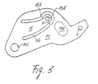
- a compensating spring element is rigidly connected to the link 14, which has the shape of at least to a limited extent in the direction parallel to the said plane of symmetry (ie essentially in the plane of the drawing of FIGS. 1-3), and transversely to the longitudinal direction of the device body 11 (ie essentially 1-3) has resilient arm 15 which has a free end 15A.
- Such a resilient arm can preferably, as is known, for example, in the case of blanks of mechanical masterworks (where, however, no flexibility is sought in the above-mentioned direction), and as in FIG Drawing is shown, by means of a suitably designed incision 14B severing the entire thickness of the link 14 to the extreme one piece with the link 14 if it is made of a material of appropriate properties (eg steel sheet).
- a suitably designed incision 14B severing the entire thickness of the link 14 to the extreme one piece with the link 14 if it is made of a material of appropriate properties (eg steel sheet).
- an opening 15A ' is provided, in which a holding pin 17A is arranged, by means of which a short web (or tab) 16 is connected at one end to the link 14.
- the web 16 has at the other end a round hole with the same diameter as the second pivot pin 14A anchored in this round hole.
- an opening 14A ' is provided for the passage of the pivot pin 14A' (preferably an elongated hole) which is larger than the diameter of the pivot pin 14A, which consequently can move freely to a certain extent in this opening 14A '.
- the link 14 is thus not rigid and / or directly connected to its pivot pin 14A.
- the end distance here is understood to mean the mutual distance between the jaw carriers 13A, 13B (in the region of their free ends) which they assume in their end position (this term will be explained later). In practice, this means that objects of different sizes (within certain limits) can be processed between the jaws carried by the jaw carriers without having to change the device, e.g. Wire end ferrules within the cross-sectional range mentioned at the beginning.
- the second pivot pin 14A passes through the device body 11 in a round opening whose diameter corresponds to the pin diameter, while for the holding pin 17 a significantly larger one in which Drawing invisible opening (possibly a circular Miger slot is provided with the center of curvature in the pin 14A) in the) device body 11.
- the two members of an organ can also be articulated to the device body 11 by such articulation and / or connecting pins and / or can be connected to members of other organs which do not penetrate the device body, but rather are fastened to the side face or short end before.
- Such a locking mechanism is to prevent a work operation from being carried out completely, and for this purpose it is designed in such a way that it only allows the actuating lever 12, and thus the jaw support 13B, to move backwards when the actuating lever 12 has reached a predetermined end position shown in FIG. 2 (which in this case is clearly determined by the end stop member mentioned earlier), in which the jaw carrier 13B is at a predetermined end distance B from the jaw carrier 13A.
- this end distance can be set automatically within certain limits.
- the invention can also be used to advantage in devices without a locking mechanism.
- the end position is generally to be understood as the greatest possible approximation of the jaw supports to each other, e.g. can be determined by mutual abutment of the handles or the like.
Landscapes
- Engineering & Computer Science (AREA)
- Mechanical Engineering (AREA)
- Life Sciences & Earth Sciences (AREA)
- Forests & Forestry (AREA)
- Gripping Jigs, Holding Jigs, And Positioning Jigs (AREA)
- Chain Conveyers (AREA)
- Manipulator (AREA)
Applications Claiming Priority (2)
| Application Number | Priority Date | Filing Date | Title |
|---|---|---|---|
| SE8804083 | 1988-11-11 | ||
| SE19888804083A SE8804083D0 (sv) | 1988-11-11 | 1988-11-11 | Taangvertyg |
Publications (3)
| Publication Number | Publication Date |
|---|---|
| EP0368824A2 true EP0368824A2 (fr) | 1990-05-16 |
| EP0368824A3 EP0368824A3 (en) | 1990-09-26 |
| EP0368824B1 EP0368824B1 (fr) | 1993-03-31 |
Family
ID=20373917
Family Applications (1)
| Application Number | Title | Priority Date | Filing Date |
|---|---|---|---|
| EP89850358A Expired - Lifetime EP0368824B1 (fr) | 1988-11-11 | 1989-10-20 | Pince |
Country Status (5)
| Country | Link |
|---|---|
| US (1) | US4982630A (fr) |
| EP (1) | EP0368824B1 (fr) |
| DE (1) | DE58903956D1 (fr) |
| ES (1) | ES2040501T3 (fr) |
| SE (1) | SE8804083D0 (fr) |
Cited By (3)
| Publication number | Priority date | Publication date | Assignee | Title |
|---|---|---|---|---|
| EP0429741A1 (fr) * | 1989-11-27 | 1991-06-05 | Weidmüller Interface GmbH & Co. | Pinces |
| US5042286A (en) * | 1988-05-09 | 1991-08-27 | C.A. Weidmuller Gmbh & Co. | Manually operated pliers-type tool |
| EP0471977A3 (en) * | 1990-08-21 | 1992-10-21 | Wezag Gmbh Werkzeugfabrik | Pliers for crimping wire end ferrules |
Families Citing this family (5)
| Publication number | Priority date | Publication date | Assignee | Title |
|---|---|---|---|---|
| US6023833A (en) * | 1999-01-29 | 2000-02-15 | Jacobsmeier; Ernest G. | Tool for installation and removal of fastener clips |
| DE29914764U1 (de) * | 1999-08-24 | 2001-01-04 | Connectool GmbH & Co., 32758 Detmold | Zange |
| US6427565B1 (en) * | 2000-11-14 | 2002-08-06 | Great Neck Saw Manufacturers, Inc. | Parallel grip plier |
| WO2014016075A1 (fr) * | 2012-07-23 | 2014-01-30 | Delphi International Operations Luxembourg S.À R.L. | Outil de sertissage manuel |
| US20150047208A1 (en) * | 2013-08-19 | 2015-02-19 | Amitai Holenberg | Double fulcrum tool |
Family Cites Families (15)
| Publication number | Priority date | Publication date | Assignee | Title |
|---|---|---|---|---|
| US1149060A (en) * | 1915-05-03 | 1915-08-03 | Walter H Loper | Wrench. |
| US1180446A (en) * | 1915-06-02 | 1916-04-25 | Rufus Harmon Sheldon | Wrench. |
| US1519938A (en) * | 1923-09-13 | 1924-12-16 | Donald V Smith | Flexible pliers |
| US1638703A (en) * | 1926-02-02 | 1927-08-09 | Charlie A Pendleton | Fuse puller |
| US2743634A (en) * | 1951-10-02 | 1956-05-01 | Thomas & Betts Corp | Flexible toggle link actuated crimping tool |
| US2910900A (en) * | 1958-01-30 | 1959-11-03 | Nat Telephone Supply Co | Adjustable multiple lever tool |
| US3204445A (en) * | 1963-04-16 | 1965-09-07 | Sargent & Co | Hand tool |
| US3575037A (en) * | 1969-01-02 | 1971-04-13 | Porter Inc H K | Distortion reducing means for jaw portion of compression tool |
| CA913346A (en) * | 1970-11-09 | 1972-10-31 | Petros Zougas | Scissors with force multiplier |
| DE2301830A1 (de) * | 1973-01-15 | 1974-07-18 | Neill Robinson Wilson | Selbsteinstellender spannschluessel |
| US4368577A (en) * | 1979-10-15 | 1983-01-18 | Emerson Electric Co. | Hand tool for cutting plastic pipe or the like |
| US4381661A (en) * | 1980-03-19 | 1983-05-03 | C. A. Weidmuller Gmbh & Co. | Tool having two working jaws |
| US4758188A (en) * | 1987-04-17 | 1988-07-19 | Myl Developments, Ltd. | Clamp-like electrical connector |
| SE8801737D0 (sv) * | 1988-05-09 | 1988-05-09 | Weidmueller C A Gmbh Co | Handverktyg |
| JP1578313S (fr) | 2016-12-08 | 2017-06-05 |
-
1988
- 1988-11-11 SE SE19888804083A patent/SE8804083D0/xx unknown
-
1989
- 1989-10-20 DE DE8989850358T patent/DE58903956D1/de not_active Expired - Fee Related
- 1989-10-20 ES ES198989850358T patent/ES2040501T3/es not_active Expired - Lifetime
- 1989-10-20 EP EP89850358A patent/EP0368824B1/fr not_active Expired - Lifetime
- 1989-11-09 US US07/433,479 patent/US4982630A/en not_active Expired - Fee Related
Cited By (3)
| Publication number | Priority date | Publication date | Assignee | Title |
|---|---|---|---|---|
| US5042286A (en) * | 1988-05-09 | 1991-08-27 | C.A. Weidmuller Gmbh & Co. | Manually operated pliers-type tool |
| EP0429741A1 (fr) * | 1989-11-27 | 1991-06-05 | Weidmüller Interface GmbH & Co. | Pinces |
| EP0471977A3 (en) * | 1990-08-21 | 1992-10-21 | Wezag Gmbh Werkzeugfabrik | Pliers for crimping wire end ferrules |
Also Published As
| Publication number | Publication date |
|---|---|
| SE8804083D0 (sv) | 1988-11-11 |
| EP0368824A3 (en) | 1990-09-26 |
| EP0368824B1 (fr) | 1993-03-31 |
| DE58903956D1 (de) | 1993-05-06 |
| ES2040501T3 (es) | 1993-10-16 |
| US4982630A (en) | 1991-01-08 |
Similar Documents
| Publication | Publication Date | Title |
|---|---|---|
| DE69611633T2 (de) | Schere | |
| DE60128533T2 (de) | Hebelschere | |
| DE69707784T2 (de) | Werkzeug mit variabler Kraft | |
| DE69013153T2 (de) | Pinzetten zum herausziehen von zecken. | |
| DE69510744T2 (de) | Schneidvorrichtung | |
| DE2642008C3 (de) | Handzange zum Abisolieren von Leiterenden | |
| CH652637A5 (de) | Werkzeug mit zwei arbeitsbacken. | |
| DE2713410A1 (de) | Zange, insbesondere zum anbringen von ohrmarkierungen bei tieren | |
| DE1616123B1 (de) | Zangenartiges chirurgisches Instrument und Verfahren zu seiner Herstellung | |
| DE2506448B2 (de) | Von Hand betätigte Rundeisenschere | |
| EP0368824B1 (fr) | Pince | |
| EP0103912A1 (fr) | Dispositif de pinces | |
| EP3944827A1 (fr) | Instrument chirurgical à mécanique de verrouillage push-push | |
| EP0321884A2 (fr) | Pince | |
| DE2755482A1 (de) | Zangenfoermiges geraet | |
| EP0074578B1 (fr) | Sécateur à effet de levier | |
| EP0635199B1 (fr) | Outil avec deux bras et deux poignées | |
| EP1080844B1 (fr) | Pince | |
| DE2555071A1 (de) | Schutzanordnung zur verhinderung des fruehzeitigen abbrechens einer arbeitsoperation | |
| EP0124919A2 (fr) | Pince à pressage munie d'une pièce d'arrêt utilisée pour presser des souliers de câble | |
| EP0512963B1 (fr) | Pince à main pour dénuder les extrémités de conducteurs | |
| DE2821212C2 (fr) | ||
| DE7607788U1 (de) | Schere, insbesondere baumschere | |
| WO2024141333A1 (fr) | Outil de coupe de type pince | |
| DE69607645T2 (de) | Mehrzweckzange |
Legal Events
| Date | Code | Title | Description |
|---|---|---|---|
| PUAI | Public reference made under article 153(3) epc to a published international application that has entered the european phase |
Free format text: ORIGINAL CODE: 0009012 |
|
| AK | Designated contracting states |
Kind code of ref document: A2 Designated state(s): DE ES FR GB IT SE |
|
| PUAL | Search report despatched |
Free format text: ORIGINAL CODE: 0009013 |
|
| AK | Designated contracting states |
Kind code of ref document: A3 Designated state(s): DE ES FR GB IT SE |
|
| 17P | Request for examination filed |
Effective date: 19900820 |
|
| 17Q | First examination report despatched |
Effective date: 19920818 |
|
| RAP3 | Party data changed (applicant data changed or rights of an application transferred) |
Owner name: WEIDMUELLER INTERFACE GMBH & CO. |
|
| GRAA | (expected) grant |
Free format text: ORIGINAL CODE: 0009210 |
|
| PGFP | Annual fee paid to national office [announced via postgrant information from national office to epo] |
Ref country code: FR Payment date: 19930324 Year of fee payment: 5 |
|
| AK | Designated contracting states |
Kind code of ref document: B1 Designated state(s): DE ES FR GB IT SE |
|
| REF | Corresponds to: |
Ref document number: 58903956 Country of ref document: DE Date of ref document: 19930506 |
|
| GBT | Gb: translation of ep patent filed (gb section 77(6)(a)/1977) |
Effective date: 19930414 |
|
| ITF | It: translation for a ep patent filed | ||
| ET | Fr: translation filed | ||
| PGFP | Annual fee paid to national office [announced via postgrant information from national office to epo] |
Ref country code: GB Payment date: 19931012 Year of fee payment: 5 |
|
| PGFP | Annual fee paid to national office [announced via postgrant information from national office to epo] |
Ref country code: DE Payment date: 19931013 Year of fee payment: 5 |
|
| PGFP | Annual fee paid to national office [announced via postgrant information from national office to epo] |
Ref country code: SE Payment date: 19931015 Year of fee payment: 5 |
|
| REG | Reference to a national code |
Ref country code: ES Ref legal event code: FG2A Ref document number: 2040501 Country of ref document: ES Kind code of ref document: T3 |
|
| PGFP | Annual fee paid to national office [announced via postgrant information from national office to epo] |
Ref country code: ES Payment date: 19931029 Year of fee payment: 5 |
|
| PLBE | No opposition filed within time limit |
Free format text: ORIGINAL CODE: 0009261 |
|
| STAA | Information on the status of an ep patent application or granted ep patent |
Free format text: STATUS: NO OPPOSITION FILED WITHIN TIME LIMIT |
|
| 26N | No opposition filed | ||
| PG25 | Lapsed in a contracting state [announced via postgrant information from national office to epo] |
Ref country code: GB Effective date: 19941020 |
|
| PG25 | Lapsed in a contracting state [announced via postgrant information from national office to epo] |
Ref country code: SE Effective date: 19941021 Ref country code: ES Free format text: LAPSE BECAUSE OF NON-PAYMENT OF DUE FEES Effective date: 19941021 |
|
| EAL | Se: european patent in force in sweden |
Ref document number: 89850358.6 |
|
| GBPC | Gb: european patent ceased through non-payment of renewal fee |
Effective date: 19941020 |
|
| PG25 | Lapsed in a contracting state [announced via postgrant information from national office to epo] |
Ref country code: FR Effective date: 19950630 |
|
| PG25 | Lapsed in a contracting state [announced via postgrant information from national office to epo] |
Ref country code: DE Effective date: 19950701 |
|
| EUG | Se: european patent has lapsed |
Ref document number: 89850358.6 |
|
| REG | Reference to a national code |
Ref country code: FR Ref legal event code: ST |
|
| REG | Reference to a national code |
Ref country code: ES Ref legal event code: FD2A Effective date: 19951113 |
|
| PG25 | Lapsed in a contracting state [announced via postgrant information from national office to epo] |
Ref country code: IT Free format text: LAPSE BECAUSE OF NON-PAYMENT OF DUE FEES Effective date: 20051020 |