EP0369521A2 - Elément de construction pour l'absorption d'énergie - Google Patents
Elément de construction pour l'absorption d'énergie Download PDFInfo
- Publication number
- EP0369521A2 EP0369521A2 EP89202812A EP89202812A EP0369521A2 EP 0369521 A2 EP0369521 A2 EP 0369521A2 EP 89202812 A EP89202812 A EP 89202812A EP 89202812 A EP89202812 A EP 89202812A EP 0369521 A2 EP0369521 A2 EP 0369521A2
- Authority
- EP
- European Patent Office
- Prior art keywords
- metal rods
- installation part
- part according
- metal
- straight
- Prior art date
- Legal status (The legal status is an assumption and is not a legal conclusion. Google has not performed a legal analysis and makes no representation as to the accuracy of the status listed.)
- Granted
Links
- 238000010276 construction Methods 0.000 title abstract 3
- 239000002184 metal Substances 0.000 claims abstract description 36
- IHQKEDIOMGYHEB-UHFFFAOYSA-M sodium dimethylarsinate Chemical class [Na+].C[As](C)([O-])=O IHQKEDIOMGYHEB-UHFFFAOYSA-M 0.000 claims abstract description 13
- 238000009434 installation Methods 0.000 claims description 15
- 238000010521 absorption reaction Methods 0.000 description 5
- 229910000831 Steel Inorganic materials 0.000 description 2
- 238000006073 displacement reaction Methods 0.000 description 2
- 239000010959 steel Substances 0.000 description 2
- 230000006835 compression Effects 0.000 description 1
- 238000007906 compression Methods 0.000 description 1
- 230000006378 damage Effects 0.000 description 1
- 238000010586 diagram Methods 0.000 description 1
- 230000010354 integration Effects 0.000 description 1
- 238000012986 modification Methods 0.000 description 1
- 230000004048 modification Effects 0.000 description 1
- 230000003068 static effect Effects 0.000 description 1
- 238000004804 winding Methods 0.000 description 1
Images


Classifications
-
- B—PERFORMING OPERATIONS; TRANSPORTING
- B62—LAND VEHICLES FOR TRAVELLING OTHERWISE THAN ON RAILS
- B62D—MOTOR VEHICLES; TRAILERS
- B62D1/00—Steering controls, i.e. means for initiating a change of direction of the vehicle
- B62D1/02—Steering controls, i.e. means for initiating a change of direction of the vehicle vehicle-mounted
- B62D1/04—Hand wheels
- B62D1/11—Hand wheels incorporating energy-absorbing arrangements, e.g. by being yieldable or collapsible
-
- F—MECHANICAL ENGINEERING; LIGHTING; HEATING; WEAPONS; BLASTING
- F16—ENGINEERING ELEMENTS AND UNITS; GENERAL MEASURES FOR PRODUCING AND MAINTAINING EFFECTIVE FUNCTIONING OF MACHINES OR INSTALLATIONS; THERMAL INSULATION IN GENERAL
- F16F—SPRINGS; SHOCK-ABSORBERS; MEANS FOR DAMPING VIBRATION
- F16F7/00—Vibration-dampers; Shock-absorbers
- F16F7/12—Vibration-dampers; Shock-absorbers using plastic deformation of members
Definitions
- the invention relates to a built-in part for absorbing energy, consisting of several, non-elastically deformable, straight metal rods arranged coaxially on a circle and fixed at their ends by a metal flange, in particular for integration in steering wheels of motor vehicles with respect to the plane of the steering wheel rim recessed steering wheel hub, with which the mounting part, which is covered on the handlebar side by an impact plate made of plastic that can be changed in shape, is firmly connected.
- components for absorbing energy which function on the principle of compressive change in shape of mechanical structures, are intended to absorb the force of the body of the driver of the motor vehicle against the steering wheel by means of deformation work in the event of collisions, i.e. the kinetic energy inherent in the driver is to be reduced over the longest possible routes and thus "small” forces, and in this way serious injuries to the driver are prevented.
- a steering wheel for motor vehicles is described in DE-B-1 912 528, whose part serving as the impact surface interacts in the event of an accident with a tubular installation part connected to the steering wheel hub for the absorption of energy.
- the built-in part has a lattice-shaped structure which is formed by a plurality of pairs of bands starting from a common point, which result in helical windings of the same pitch and opposite sense of pitch, the crossing points of the pairs of bands being evenly distributed over the circumference.
- an essential part of the deformation path goes through the pairs of bands and their Junction points are lost because they are stacked on top of each other under pressure load and thus reduce the deformation path.
- the tubular disadvantage described in DE-A-2 623 521 for absorbing energy also has the same disadvantage, with numerous systematically arranged openings, the wall sections which are effective in changing the shape being supposed to have approximately the same size.
- a built-in part for absorbing energy which consists of an elastically or plastically deformable metal body, which is formed from support elements arranged in a circle next to one another, such as webs, struts, rods or the like, and which at Pressure load on the steering wheel should result in an outward buckling of the support elements due to the arrangement of outwardly directed kink points.
- the disadvantage of such a built-in part is that too little energy is dissipated on the deformation path with sometimes dangerously high pressure force peaks. This disadvantage also applies to all of the above-mentioned tubular installation parts for absorbing energy.
- the object of the present invention is therefore to design the built-in part for absorbing energy in such a way that, in the event of a collision, the deformation force initially increases relatively steeply and then remains almost constant over the greatest length of the deformation path, so that the compression force path Characteristic curve results in a trapezoidal shape below the curve, which characterizes an installation part with ideal energy absorption capacity.
- the transverse dimensions of the prismatic metal bars are each small in relation to their longitudinal dimensions, the metal bars below the Influence of compressive force acting in the axial direction can be buckled in the direction of the larger main moment of inertia and in which a straight toothing extending transversely to the longitudinal direction is attached to at least one of the broad sides running perpendicular to the axis of the larger main moment of inertia and forming a right angle with the radius of the component.
- a built-in part designed in this way has an ideal energy absorption capacity under both static and dynamic pressure loads, since the characteristic curve for the dependence of the deformation force on the deformation path has an approximately trapezoidal shape in both pressure load cases.
- the buckling direction of the metal rods which takes place in the direction of their major principal moment of inertia, can be predetermined in that, according to a particular feature of the invention, the straight toothing is attached to the broad side opposite the desired buckling direction, preferably in the area of its free buckling length.
- An optimal energy absorption capacity can be achieved if the straight toothing of the metal rods is in the area of their free side on the broad side opposite the intended buckling direction Kink length and in the areas between their fastenings with the flanges and the turning points of the bend on the broad side pointing in the desired bend direction.
- the straight toothing of the metal bars extends over their broad sides.
- teeth connected in one piece with the comb are arranged in comb-like fashion on one or both of the narrow sides of the metal rods and bent out to form the straight toothing on the broad sides.
- a modification of this embodiment is to be seen in the fact that the comb-like tines are bent up to form the straight toothing so that they form a right angle with the broad side of the metal bars.
- the teeth of the straight toothing have an involute, cycloid, circular arc or U profile with vertical or inclined tooth flanks.
- FIG. 1 shows a schematic representation of a longitudinal section taken along the steering axis through a steering wheel connected to an installation part for absorbing energy
- FIG. 2 shows a side view of an installation part after the shape has changed.
- the built-in part (1) consists of several metal rods (2) made of steel of type St37, which are arranged coaxially on a circle and cannot be resiliently shaped, and which are firmly connected to one another at their ends by a steel flange (3, 4).
- the steering wheel spokes (6) connected to the steering wheel rim (5) are attached to the handlebar flange (3).
- the steering wheel hub (8) placed on the steering column (7) is fastened in the flange (4) on the steering column side.
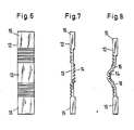
- the metal rod (12) shown in FIG. 6 as a side view in the direction of the axis of the major principal moment of inertia, which is shown in FIG. 7 as a side view perpendicular to the direction of the axis of the major principal moment of inertia, has in the area of the free buckling length (13) on the A straight toothing (14) with rectangular teeth is opposite the broadside on the opposite side.
- the straight toothing (14) runs on the one pointing in the buckling direction Broadside. 8 shows the metal rod (12) after the pressure has been applied.
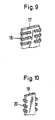
- Fig. 9 shows a perspective view of the section of a metal rod (17), in which the straight toothing is formed by tines (18) attached in comb-like manner on its two narrow sides and bent on one of the broad sides.
- Fig. 10 the portion of a metal rod (19) is shown in a perspective view, on the narrow sides of which comb-like teeth acting as straight teeth (20) are bent so that they form an angle of 90 ° with one of the broad sides.
- the deformation force is plotted over the deformation path, the dash-dotted line representing the deformation behavior of an ideal and the fully drawn curve representing the deformation behavior of the built-in part designed to absorb energy. It can be seen that the energy absorption capacity of the built-in part (1) designed according to the invention deviates comparatively slightly from the ideal course of the compressive force-displacement characteristic for a built-in part for absorbing energy.
Landscapes
- Engineering & Computer Science (AREA)
- General Engineering & Computer Science (AREA)
- Mechanical Engineering (AREA)
- Chemical & Material Sciences (AREA)
- Combustion & Propulsion (AREA)
- Transportation (AREA)
- Steering Controls (AREA)
- Vibration Dampers (AREA)
Applications Claiming Priority (2)
| Application Number | Priority Date | Filing Date | Title |
|---|---|---|---|
| DE3838594A DE3838594A1 (de) | 1988-11-15 | 1988-11-15 | Einbauteil zur absorption von energie |
| DE3838594 | 1988-11-15 |
Publications (3)
| Publication Number | Publication Date |
|---|---|
| EP0369521A2 true EP0369521A2 (fr) | 1990-05-23 |
| EP0369521A3 EP0369521A3 (fr) | 1991-11-06 |
| EP0369521B1 EP0369521B1 (fr) | 1995-02-22 |
Family
ID=6367163
Family Applications (1)
| Application Number | Title | Priority Date | Filing Date |
|---|---|---|---|
| EP89202812A Expired - Lifetime EP0369521B1 (fr) | 1988-11-15 | 1989-11-08 | Elément de construction pour l'absorption d'énergie |
Country Status (9)
| Country | Link |
|---|---|
| US (1) | US5005863A (fr) |
| EP (1) | EP0369521B1 (fr) |
| JP (1) | JPH02186140A (fr) |
| BR (1) | BR8905785A (fr) |
| DE (2) | DE3838594A1 (fr) |
| ES (1) | ES2070170T3 (fr) |
| MX (1) | MX172246B (fr) |
| PT (1) | PT92310B (fr) |
| TR (1) | TR24804A (fr) |
Cited By (3)
| Publication number | Priority date | Publication date | Assignee | Title |
|---|---|---|---|---|
| WO1995023299A1 (fr) * | 1994-02-25 | 1995-08-31 | Michel Malvy | Dispositif d'absorption d'energie par deformation plastique, notamment pour volant de direction de vehicule, et volant de direction equipe d'un tel dispositif |
| EP0733514A1 (fr) * | 1995-03-24 | 1996-09-25 | MST Automotive GmbH Automobil-Sicherheitstechnik | Volant de direction de sécurité |
| FR3016202A1 (fr) * | 2014-01-07 | 2015-07-10 | Autotech Engineering Aie | Poutre metallique a angle de flexion limite |
Families Citing this family (16)
| Publication number | Priority date | Publication date | Assignee | Title |
|---|---|---|---|---|
| US5205186A (en) * | 1989-05-23 | 1993-04-27 | Eldra-Kunststofftechnik Gmbh | Steering wheel |
| US6268546B1 (en) | 1989-07-19 | 2001-07-31 | Calgene Llc | Ovary-tissue transcriptional factors |
| DE4105026C1 (fr) * | 1991-02-19 | 1992-02-20 | Mercedes-Benz Aktiengesellschaft, 7000 Stuttgart, De | |
| JPH0575057U (ja) * | 1992-03-13 | 1993-10-12 | 日本精工株式会社 | 衝撃吸収式ステアリングコラム装置 |
| JPH07304457A (ja) * | 1994-05-11 | 1995-11-21 | Toei Sangyo Kk | ステアリングホイール |
| GB2300606A (en) * | 1995-05-10 | 1996-11-13 | Dick Lucien Chitolie | A safety steering wheel |
| DE19729893C2 (de) * | 1997-07-12 | 1999-04-29 | Mc Micro Compact Car Ag | Lenksäule in einem Kraftfahrzeug |
| DE19747873A1 (de) * | 1997-10-20 | 1999-04-22 | Petri Ag | Energie absorbierendes Lenkrad |
| DE19747423C1 (de) * | 1997-10-27 | 1999-04-29 | Bsrs Restraint Syst Gmbh | Dynamische Knieschutzeinrichtung |
| GB9817536D0 (en) * | 1998-08-13 | 1998-10-07 | Rover Group | A motor vehicle |
| US7188866B2 (en) * | 2004-02-26 | 2007-03-13 | Delphi Technologies, Inc | Steering column assembly and method of fabricating the same |
| DE202004003406U1 (de) | 2004-02-27 | 2004-05-13 | Takata-Petri Ag | Lenkanordnung für Kraftfahrzeuge |
| GB2426806A (en) * | 2005-04-27 | 2006-12-06 | Ford Global Tech Llc | A structural element designed to withstand a transverse load tending to bend the element |
| CN101157363A (zh) * | 2006-10-07 | 2008-04-09 | 阎跃军 | 方向操作装置 |
| US20120048056A1 (en) * | 2010-08-31 | 2012-03-01 | Autoliv Asp, Inc. | Adaptive energy absorption steering wheel |
| JP7052310B2 (ja) * | 2017-06-20 | 2022-04-12 | 日本精工株式会社 | ステアリング装置及び中間シャフト |
Family Cites Families (16)
| Publication number | Priority date | Publication date | Assignee | Title |
|---|---|---|---|---|
| US3373629A (en) * | 1966-04-29 | 1968-03-19 | Gen Motors Corp | Steering column assembly |
| US3495474A (en) * | 1966-11-24 | 1970-02-17 | Nissan Motor | Impact absorbing means for vehicles |
| FR1549902A (fr) * | 1966-12-31 | 1968-12-13 | ||
| US3482466A (en) * | 1967-01-24 | 1969-12-09 | Helmut Orlich | Torsion device for steering columns |
| US3508633A (en) * | 1967-05-17 | 1970-04-28 | Nissan Motor | Plastically deformable impact absorbing means for vehicles |
| US3523587A (en) * | 1967-10-02 | 1970-08-11 | Ara Inc | Energy absorbing steering mechanism for vehicles |
| FR1586115A (fr) * | 1968-07-02 | 1970-02-13 | ||
| DE1912528B2 (de) * | 1969-03-12 | 1975-01-23 | Volkswagenwerk Ag, 3180 Wolfsburg | Sicherheitslenkrad für Kraftfahrzeuge |
| DE2042220B2 (de) * | 1970-08-26 | 1977-04-28 | Daimler-Benz Ag, 7000 Stuttgart | Verformbare instrumententafel in einem kraftfahrzeug |
| DE2058411A1 (de) * | 1970-11-27 | 1972-06-08 | Daimler Benz Ag | Sicherheitslenkung |
| GB1359760A (en) * | 1971-05-28 | 1974-07-10 | Daimler Benz Ag | Collapsible vehicle-steering column |
| DE2614041A1 (de) * | 1976-04-01 | 1977-10-06 | Petri Ag | Energieabsorptionselement |
| US4312430A (en) * | 1979-12-12 | 1982-01-26 | Izumi Motor Co., Ltd. | Shock absorber |
| DE3045141C2 (de) * | 1980-11-29 | 1987-07-09 | Messerschmitt-Bölkow-Blohm GmbH, 8000 München | Sicherheitslenksäule für Kraftfahrzeuge |
| DE3049425C2 (de) * | 1980-12-30 | 1991-09-05 | Messerschmitt-Bölkow-Blohm GmbH, 8000 München | Aufprall-Schutz-Bauteil |
| DE3321197C2 (de) * | 1983-06-11 | 1986-09-25 | Messerschmitt-Bölkow-Blohm GmbH, 8000 München | Rohr, insbesondere für eine Sicherheitslenksäule für Kraftfahrzeuge |
-
1988
- 1988-11-15 DE DE3838594A patent/DE3838594A1/de not_active Withdrawn
-
1989
- 1989-11-08 ES ES89202812T patent/ES2070170T3/es not_active Expired - Lifetime
- 1989-11-08 DE DE58909030T patent/DE58909030D1/de not_active Expired - Lifetime
- 1989-11-08 EP EP89202812A patent/EP0369521B1/fr not_active Expired - Lifetime
- 1989-11-13 JP JP1294766A patent/JPH02186140A/ja active Pending
- 1989-11-13 US US07/436,275 patent/US5005863A/en not_active Expired - Fee Related
- 1989-11-14 BR BR898905785A patent/BR8905785A/pt not_active Application Discontinuation
- 1989-11-14 PT PT92310A patent/PT92310B/pt not_active IP Right Cessation
- 1989-11-15 TR TR89/0963A patent/TR24804A/xx unknown
- 1989-11-15 MX MX018377A patent/MX172246B/es unknown
Cited By (7)
| Publication number | Priority date | Publication date | Assignee | Title |
|---|---|---|---|---|
| WO1995023299A1 (fr) * | 1994-02-25 | 1995-08-31 | Michel Malvy | Dispositif d'absorption d'energie par deformation plastique, notamment pour volant de direction de vehicule, et volant de direction equipe d'un tel dispositif |
| FR2716703A1 (fr) * | 1994-02-25 | 1995-09-01 | Malvy Michel | Dispositif d'absorption d'énergie par déformation plastique, notamment pour volant de direction de véhicule, et volant de direction équipé d'un tel dispositif. |
| EP0733514A1 (fr) * | 1995-03-24 | 1996-09-25 | MST Automotive GmbH Automobil-Sicherheitstechnik | Volant de direction de sécurité |
| FR3016202A1 (fr) * | 2014-01-07 | 2015-07-10 | Autotech Engineering Aie | Poutre metallique a angle de flexion limite |
| WO2015104268A2 (fr) | 2014-01-07 | 2015-07-16 | Autotech Engineering, A.I.E. | Poutre metallique a angle de flexion limite |
| WO2015104268A3 (fr) * | 2014-01-07 | 2015-09-03 | Autotech Engineering, A.I.E. | Poutre metallique a angle de flexion limite |
| CN105899423A (zh) * | 2014-01-07 | 2016-08-24 | 自动工程公司 | 具有有限弯曲角的金属梁 |
Also Published As
| Publication number | Publication date |
|---|---|
| TR24804A (tr) | 1992-03-26 |
| DE3838594A1 (de) | 1990-05-17 |
| ES2070170T3 (es) | 1995-06-01 |
| EP0369521A3 (fr) | 1991-11-06 |
| US5005863A (en) | 1991-04-09 |
| DE58909030D1 (de) | 1995-03-30 |
| PT92310B (pt) | 1997-02-28 |
| JPH02186140A (ja) | 1990-07-20 |
| PT92310A (pt) | 1990-05-31 |
| MX172246B (es) | 1993-12-09 |
| EP0369521B1 (fr) | 1995-02-22 |
| BR8905785A (pt) | 1990-06-12 |
Similar Documents
| Publication | Publication Date | Title |
|---|---|---|
| EP0369521B1 (fr) | Elément de construction pour l'absorption d'énergie | |
| EP0369520B1 (fr) | Elément de construction pour l'absorption d'énergie | |
| DE69720171T2 (de) | Energieabsorbierende Struktur für ein Kraftfahrzeug | |
| DE3837190C1 (fr) | ||
| DE602005004514T2 (de) | Stossfängerstange für ein fahrzeug | |
| DE2751068C2 (de) | Stoßabsorbierende Sicherheitslenksäule für Kraftfahrzeuge | |
| DE102013202607A1 (de) | Aufprallabsorptionselement | |
| DE2313588A1 (de) | Bodenrahmen fuer kraftfahrzeuge | |
| DE3426281A1 (de) | Stossdaempfendes schneckenradgetriebe | |
| DE3617099C2 (fr) | ||
| WO2001089909A1 (fr) | Mecanisme telescopique | |
| DE19948830A1 (de) | Teleskopausleger für Krane | |
| DE2853244A1 (de) | Stossfaenger fuer kraftfahrzeuge | |
| DE102021006094A1 (de) | Energieabsorptionsvorrichtung für ein zumindest teilweise elektrisch betriebenes Kraftfahrzeug | |
| DE3007897C2 (de) | Lastbügel für Fahrzeuge, insbesondere für Kraftfahrzeuge | |
| DE69713829T2 (de) | Stossenergieaufnehmende Lenksäuleneinrichtung,insbesondere für ein Kraftfahrzeug | |
| DE2900941C2 (de) | Stoßfänger für Fahrzeuge | |
| DE1625261A1 (de) | Feder aus Gummi oder aehnlichen nachgiebig-elastischen Werkstoffen | |
| DE29808143U1 (de) | Aufpralldämpfer für Kraftfahrzeuge | |
| WO1992012358A1 (fr) | Ressort a boudin | |
| DE2318385A1 (de) | Einrichtung zur absorption von energie durch plastische verformung | |
| DE102005025353A1 (de) | Schutzvorrichtung für Kraftfahrzeuge | |
| DE4333891C2 (de) | Längsführung insbesondere für Kraftfahrzeugsitze | |
| DE2135872C2 (de) | Stoßfängerbefestigung für Kraftfahrzeuge | |
| DE10108352B4 (de) | Strukturbauelement für den Fahrzeugbau |
Legal Events
| Date | Code | Title | Description |
|---|---|---|---|
| PUAI | Public reference made under article 153(3) epc to a published international application that has entered the european phase |
Free format text: ORIGINAL CODE: 0009012 |
|
| AK | Designated contracting states |
Kind code of ref document: A2 Designated state(s): DE ES FR GB IT SE |
|
| PUAL | Search report despatched |
Free format text: ORIGINAL CODE: 0009013 |
|
| AK | Designated contracting states |
Kind code of ref document: A3 Designated state(s): DE ES FR GB IT SE |
|
| 17P | Request for examination filed |
Effective date: 19911207 |
|
| 17Q | First examination report despatched |
Effective date: 19930730 |
|
| GRAA | (expected) grant |
Free format text: ORIGINAL CODE: 0009210 |
|
| AK | Designated contracting states |
Kind code of ref document: B1 Designated state(s): DE ES FR GB IT SE |
|
| ET | Fr: translation filed | ||
| REF | Corresponds to: |
Ref document number: 58909030 Country of ref document: DE Date of ref document: 19950330 |
|
| ITF | It: translation for a ep patent filed | ||
| REG | Reference to a national code |
Ref country code: ES Ref legal event code: FG2A Ref document number: 2070170 Country of ref document: ES Kind code of ref document: T3 |
|
| GBT | Gb: translation of ep patent filed (gb section 77(6)(a)/1977) |
Effective date: 19950518 |
|
| PGFP | Annual fee paid to national office [announced via postgrant information from national office to epo] |
Ref country code: SE Payment date: 19950906 Year of fee payment: 7 |
|
| PGFP | Annual fee paid to national office [announced via postgrant information from national office to epo] |
Ref country code: FR Payment date: 19950915 Year of fee payment: 7 |
|
| PGFP | Annual fee paid to national office [announced via postgrant information from national office to epo] |
Ref country code: GB Payment date: 19951026 Year of fee payment: 7 |
|
| PGFP | Annual fee paid to national office [announced via postgrant information from national office to epo] |
Ref country code: ES Payment date: 19951130 Year of fee payment: 7 |
|
| PGFP | Annual fee paid to national office [announced via postgrant information from national office to epo] |
Ref country code: DE Payment date: 19951221 Year of fee payment: 7 |
|
| PLBE | No opposition filed within time limit |
Free format text: ORIGINAL CODE: 0009261 |
|
| STAA | Information on the status of an ep patent application or granted ep patent |
Free format text: STATUS: NO OPPOSITION FILED WITHIN TIME LIMIT |
|
| 26N | No opposition filed | ||
| PG25 | Lapsed in a contracting state [announced via postgrant information from national office to epo] |
Ref country code: DE Effective date: 19960702 |
|
| PG25 | Lapsed in a contracting state [announced via postgrant information from national office to epo] |
Ref country code: GB Effective date: 19961108 |
|
| PG25 | Lapsed in a contracting state [announced via postgrant information from national office to epo] |
Ref country code: SE Effective date: 19961109 Ref country code: ES Free format text: LAPSE BECAUSE OF NON-PAYMENT OF DUE FEES Effective date: 19961109 |
|
| GBPC | Gb: european patent ceased through non-payment of renewal fee |
Effective date: 19961108 |
|
| PG25 | Lapsed in a contracting state [announced via postgrant information from national office to epo] |
Ref country code: FR Effective date: 19970731 |
|
| EUG | Se: european patent has lapsed |
Ref document number: 89202812.7 |
|
| REG | Reference to a national code |
Ref country code: FR Ref legal event code: ST |
|
| REG | Reference to a national code |
Ref country code: ES Ref legal event code: FD2A Effective date: 19971213 |
|
| PG25 | Lapsed in a contracting state [announced via postgrant information from national office to epo] |
Ref country code: IT Free format text: LAPSE BECAUSE OF NON-PAYMENT OF DUE FEES;WARNING: LAPSES OF ITALIAN PATENTS WITH EFFECTIVE DATE BEFORE 2007 MAY HAVE OCCURRED AT ANY TIME BEFORE 2007. THE CORRECT EFFECTIVE DATE MAY BE DIFFERENT FROM THE ONE RECORDED. Effective date: 20051108 |