EP0369524A2 - Rack de distribution pour l'établissement des connections optiques à option libre - Google Patents
Rack de distribution pour l'établissement des connections optiques à option libre Download PDFInfo
- Publication number
- EP0369524A2 EP0369524A2 EP89202824A EP89202824A EP0369524A2 EP 0369524 A2 EP0369524 A2 EP 0369524A2 EP 89202824 A EP89202824 A EP 89202824A EP 89202824 A EP89202824 A EP 89202824A EP 0369524 A2 EP0369524 A2 EP 0369524A2
- Authority
- EP
- European Patent Office
- Prior art keywords
- end termination
- optical
- termination units
- storage
- cables
- Prior art date
- Legal status (The legal status is an assumption and is not a legal conclusion. Google has not performed a legal analysis and makes no representation as to the accuracy of the status listed.)
- Granted
Links
Images

Classifications
-
- G—PHYSICS
- G02—OPTICS
- G02B—OPTICAL ELEMENTS, SYSTEMS OR APPARATUS
- G02B6/00—Light guides; Structural details of arrangements comprising light guides and other optical elements, e.g. couplings
- G02B6/44—Mechanical structures for providing tensile strength and external protection for fibres, e.g. optical transmission cables
- G02B6/4439—Auxiliary devices
- G02B6/444—Systems or boxes with surplus lengths
- G02B6/4453—Cassettes
- G02B6/4454—Cassettes with splices
-
- G—PHYSICS
- G02—OPTICS
- G02B—OPTICAL ELEMENTS, SYSTEMS OR APPARATUS
- G02B6/00—Light guides; Structural details of arrangements comprising light guides and other optical elements, e.g. couplings
- G02B6/44—Mechanical structures for providing tensile strength and external protection for fibres, e.g. optical transmission cables
- G02B6/4439—Auxiliary devices
- G02B6/444—Systems or boxes with surplus lengths
- G02B6/4452—Distribution frames
- G02B6/44524—Distribution frames with frame parts or auxiliary devices mounted on the frame and collectively not covering a whole width of the frame or rack
-
- G—PHYSICS
- G02—OPTICS
- G02B—OPTICAL ELEMENTS, SYSTEMS OR APPARATUS
- G02B6/00—Light guides; Structural details of arrangements comprising light guides and other optical elements, e.g. couplings
- G02B6/44—Mechanical structures for providing tensile strength and external protection for fibres, e.g. optical transmission cables
- G02B6/4439—Auxiliary devices
- G02B6/444—Systems or boxes with surplus lengths
- G02B6/44528—Patch-cords; Connector arrangements in the system or in the box
Definitions
- the invention relates to a switching distributor for producing freely selectable optical plug connections between the optical fiber incoming optical cables and the optical fiber outgoing optical cables by means of optical patch cords.
- the patch cords are spliced on one side with the individual optical fibers (LWL) of the optical fibers ending in the end termination units of the outgoing optical cables.
- the plug element of the free end of the patch cords can be freely connected to plug-in connection elements of the fiber optic cables of the incoming optical cables, which also end in end termination units.
- the patch cords hang freely. They form loops corresponding to the excess length that is not required for a switching path.
- switching distributors In particular when building a fiber optic local network, switching distributors must be available, by means of which a large number (e.g. 100) of optical cables arriving (fiber optic cables) can be connected with a mostly larger number (e.g. 200) fiber optic outgoing optical cables in any combination.
- the switching connections must be able to be changed as often as required. Such connections are made using the patch cords.
- the patch cords are subject to considerable mechanical stress. Damage cannot be ruled out, especially not if it is freely suspended.
- the invention has for its object to design a switching distributor of the type mentioned in such a way that any switching connections are easy to manufacture. Damage to the patch cords should be largely excluded. At least such damage should not have any adverse effects on the optical cables routed into the switch distributor.
- the solution is achieved in that the optical fiber groups of the incoming optical cables are connected to a first group of adjacent end termination units, that the optical fiber groups of the outgoing optical cables are connected to a second group of adjacent end termination units, that the individual optical fibers of the incoming and of the outgoing cables are connected to optical plug connection elements arranged on the end termination units, that the marshalling lines are connected on both sides to mating plug elements, and that the excess length sections of the marshalling lines which are not required for the production of a respective plug connection can be stored in storage elements.
- optical fibers of the optical cables led into the switch distributor are firmly connected to the plug elements of the end termination units. Subsequent interventions in the optical line path to the plug elements are not necessary, since switching connections to the patch cords are made exclusively via plug connectors.
- end termination units are designed as plug-in modules which can be inserted into the switching distributor, on which a group of optical fibers is held strain-relieved, either of an incoming or an outgoing cable, and which memory recordings have for the insertion lengths of the optical fibers required for making splice connections .
- the respective end termination unit guided on drawer guides in the switch distributor is pulled out, so that the required operations can be carried out freely on the freely accessible end termination unit.
- At least some of the end termination units are spatially assigned to a number of storage elements corresponding to the number of plug connection elements of the end termination unit.
- the immediate proximity of the storage for the storage elements to an associated plug-in connection element of an end termination unit means that the free routing of the shunting lines is very short and a systematic routing arrangement is possible.
- the storage brackets are part of the end termination units. Then the routing routes of a patch cord to its associated plug connection element are particularly short and clear.
- Each plug connection element of a fiber optic cable of an incoming cable can then be assigned a specific storage space for a patch cord.
- a fitter then knows, without searching, which patch cord to choose for a specific switching path. This automatically gives you a convenient way of guiding the maneuvering performance.
- a space-saving and easy-to-use embodiment is that the storage receptacles and the storage brackets are arranged on opposite sides of the end termination units.
- a favorable insertion option for the storage elements results from the fact that the storage elements for the marshalling lines can be inserted into the storage brackets essentially in the direction perpendicular to the insertion direction for the end termination units.
- the storage brackets can be designed so that storage elements can be inserted from both sides of the extended end termination units.
- An orderly crossing-free routing of the marshalling lines in the area of the end termination units is made possible by the fact that guide brackets for the ends of the marshalling lines starting from each storage element are assigned to the storage brackets.
- a preferred solution is characterized in that the groups of end termination units of the incoming and outgoing cables are arranged in a common line, and that the guide holders for the switching lengths of the jumper lines, preferably on both sides, are arranged next to the line of end termination units.
- Storage elements of the type described in DE-OS 37 06 518 are preferably suitable for storing the unnecessary excess lengths of the marshalling line.
- patch cords are loosely guided through an S-shaped channel of their storage elements and excess lengths of the patch cords can be wound in parallel and together around a winding core of the storage elements.
- the end termination units have two memory receptacles, the first of which is used to insert a storage length of the entirety of the optical fibers guided in the end termination unit, while in the second memory receptacle for the production of the splice connections between the individual optical fibers and the pigtail -LWL of the connector elements required lengths of the LWL and the pigtail-LWL can be stored.
- Lengths of availability of the optical fibers supplied by an optical cable are initially stored in the first memory receptacle. Thereafter, the available lengths required for making the splice connections with the pigtail fiber optics of the plug-in connection elements can be drawn from the first memory receptacle and, after the splice points have been completed, stored together with the pigtail fiber optics in the second memory receptacle.
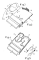
- end termination units 2 and 3 are arranged one above the other and can be pulled out like a drawer in the lower region.
- the end termination unit 2 is shown in the extended state.
- These lower end termination units are each connected to a group of ten fiber optic cables of an incoming optical cable which are combined into a flat band.
- Each of these ten fiber optics is optically connected to a plug connection element of the connector strip 4.
- end termination units 5 are arranged so that they can be pulled out one above the other.
- These optical fibers can also be combined to form a flat strip or they can be individual optical fibers of a loose tube.
- the number of end termination units 5 for outgoing cables is greater than the corresponding number for incoming cables, since there are many more outgoing than incoming optical lines.
- An optical connection must be switchable from each plug connection element of each lower end termination unit to any plug connection element of each upper end termination unit.
- Single-core patch cables 7 and 8 are used for this purpose, which have a mating connector element on both sides of the mating connector elements of the connector strips 4 and 6.
- the length of the patch cords 7 and 8 corresponds to the longest possible switching path. Length sections that are not required for shorter switching paths are wrapped in flat storage elements 9, of which a number corresponding to the number of plug-in connection elements of an end termination unit 2 can be inserted laterally into receiving brackets 10 of an end termination unit 2. No storage elements need to be assigned to the upper end termination units 5, since only a maximum of each of the optical fibers of the incoming cables is to be connected to one optical fiber of the outgoing cables.
- the jumper 7 creates an optical connection between the plug connection elements 11 and 12.
- the jumper 8 connects the plug connection elements 13 and 14. In the same way, a large number of further switching connections can be made in any way.
- the ends of the shunting lines 7 and 8 leading to the upper end termination units 5, which are fixed to guide brackets 31 and 15 starting from their storage elements 9, are outside the extension area of the end termination units 2, 3 and 5 on the edge of the housing 1 in guide brackets 16 inserted, which are designed as eyelets opened by insertion slots.
- a small free length is to be provided, which allows the end termination units 2 and 3 to be pulled out without undue curvature of the marshalling lines.
- This free length can be kept short in that the receptacle brackets 31 and 15 are arranged set back from the side of the plug connector 4 to the storage elements 9.
- end termination units 2 and the associated memory elements 9 are explained in more detail with reference to FIGS. 2 to 5.
- an end termination unit 2 according to FIG. 1 can be seen enlarged in the same position.
- details of the construction have been omitted.
- the storage brackets 10 and 30 for a plurality of storage elements 9 to be inserted each consist of two parts, a flat part and one of the circular outer contour of the storage elements 9 adapted curved part, which in the storage brackets 10 and 30 are arranged one above the other in reverse spatial order.
- Five storage elements 9 can be inserted one above the other in the guides of the lower sections from the right, and five further storage elements 9 in the guides of the upper sections from the left in the direction of arrow 19.
- the marshalling line 8 is guided with a central region 8a through an S-shaped channel of the storage element 9.
- the storage elements are preferably designed in two parts.
- the insertion channel which is initially openly accessible, is covered by joining the two parts.
- both ends 8b and 8c can be simultaneously wrapped in parallel in an annular groove of the storage element 9 which is open radially outwards.
- the shorter end 8c with the plug connection element 20 is used for connection to the connector strip 4, while the longer end 8b with the plug connection element 21 is provided for connection to a connector strip 6 of an upper end termination unit 5 indicated in FIG. 1.
- the storage element can, after the plug connections have been made and the ends 8b placed in the guide holder 15 and the ends 8c placed in the guide holders 15 and 18, in such a middle longitudinal position Shunting cable are pushed so that unnecessary lengths of the ends 8b and 8c disappear in the storage element during the subsequent winding.
- the end of the fiber optic flat belt 27 is guided by a not shown in the drawing channel in at 90 o rotated flat position in the memory receptacle 23 (hatched area in Fig. 5).
- splice connections 29 are to be made with the pigtails 26 of the plug connection elements of the plug connector 4
- a required length of the winding 24 is drawn out of the memory receptacle 23.
- the excess lengths of the pigtails 26 and the portion of the fiber optic ribbon 27 that are no longer required after the splicing are stored in the memory receptacle 23 (see winding 28 in FIG. 5).
Landscapes
- Physics & Mathematics (AREA)
- General Physics & Mathematics (AREA)
- Optics & Photonics (AREA)
- Mechanical Coupling Of Light Guides (AREA)
- Light Guides In General And Applications Therefor (AREA)
- Mechanical Light Control Or Optical Switches (AREA)
- Structure Of Telephone Exchanges (AREA)
- Optical Communication System (AREA)
Applications Claiming Priority (2)
| Application Number | Priority Date | Filing Date | Title |
|---|---|---|---|
| DE3838428A DE3838428A1 (de) | 1988-11-12 | 1988-11-12 | Schaltverteiler zur herstellung von frei waehlbaren optischen steckverbindungen |
| DE3838428 | 1988-11-12 |
Publications (3)
| Publication Number | Publication Date |
|---|---|
| EP0369524A2 true EP0369524A2 (fr) | 1990-05-23 |
| EP0369524A3 EP0369524A3 (fr) | 1991-03-06 |
| EP0369524B1 EP0369524B1 (fr) | 1994-06-22 |
Family
ID=6367058
Family Applications (1)
| Application Number | Title | Priority Date | Filing Date |
|---|---|---|---|
| EP89202824A Expired - Lifetime EP0369524B1 (fr) | 1988-11-12 | 1989-11-08 | Rack de distribution pour l'établissement des connections optiques à option libre |
Country Status (5)
| Country | Link |
|---|---|
| US (1) | US5024498A (fr) |
| EP (1) | EP0369524B1 (fr) |
| JP (1) | JPH02211408A (fr) |
| DE (2) | DE3838428A1 (fr) |
| ES (1) | ES2058482T3 (fr) |
Cited By (10)
| Publication number | Priority date | Publication date | Assignee | Title |
|---|---|---|---|---|
| DE4107228A1 (de) * | 1990-03-20 | 1991-09-26 | Loh Kg Rittal Werk | Lwl(lichtwellenleiter)-spleissbox |
| GB2242757A (en) * | 1990-03-20 | 1991-10-09 | Loh Kg Rittal Werk | Slidable light wave conductor splicing box |
| EP0474091A1 (fr) * | 1990-09-03 | 1992-03-11 | Reichle + De-Massari AG Elektro-Ingenieure | Boîte d'extrémité pour câbles de transmission de signaux, particulièrement pour câbles à fibres de verre |
| DE4126125C1 (en) * | 1991-08-07 | 1992-10-22 | Rittal-Werk Rudolf Loh Gmbh & Co Kg, 6348 Herborn, De | Fibre=optic cable splice installation - has splice cassette arranged on rectangular board with fixing holes and cable clamps |
| EP0514638A1 (fr) * | 1991-03-22 | 1992-11-25 | The Siemon Company | Panneau de communication fibre optique |
| FR2682488A1 (fr) * | 1991-10-15 | 1993-04-16 | Capelle Bruno | Tete de cables modulaire a fibres optiques de grande capacite . |
| EP0536496A3 (fr) * | 1991-10-05 | 1994-03-23 | Krone Ag | |
| DE4308228C1 (de) * | 1993-03-16 | 1994-10-20 | Quante Ag | Hauptverteiler für Lichtleitfasern der Kommunikationstechnik |
| EP0623832A1 (fr) * | 1993-05-05 | 1994-11-09 | KRONE Aktiengesellschaft | Monture de répartition pour cables |
| EP2749921A1 (fr) * | 2012-12-31 | 2014-07-02 | illi-sys | Dispositif de répartition pour guide à fibres optiques |
Families Citing this family (86)
| Publication number | Priority date | Publication date | Assignee | Title |
|---|---|---|---|---|
| US5071211A (en) * | 1988-12-20 | 1991-12-10 | Northern Telecom Limited | Connector holders and distribution frame and connector holder assemblies for optical cable |
| ES2100189T3 (es) * | 1990-10-04 | 1997-06-16 | Alcatel Cable Interface | Cajetin de conexion optica. |
| DE4034832A1 (de) * | 1990-11-02 | 1992-05-07 | Rheydt Kabelwerk Ag | Anordnung zum rangieren von lichtwellenleitern |
| EP0519210B1 (fr) * | 1991-06-10 | 1996-02-28 | International Business Machines Corporation | Connecteur optique rétractable pour des ordinateurs |
| ES1019586Y (es) * | 1991-12-12 | 1992-11-01 | Telefonica De Espana, S.A. | Conjunto terminal de empalme y reparticion optica modular. |
| US5189723A (en) * | 1992-01-06 | 1993-02-23 | Adc Telecommunications, Inc. | Below ground cross-connect/splice sytem (BGX) |
| GB2265725B (en) * | 1992-04-02 | 1995-07-12 | Northern Telecom Ltd | Submarine repeaters |
| US5274731A (en) * | 1992-12-24 | 1993-12-28 | Adc Telecommunications, Inc. | Optical fiber cabinet |
| DE4334022C1 (de) * | 1993-10-06 | 1995-03-02 | Rose Walter Gmbh & Co Kg | Vorrichtung zur Aufnahme von Spleißkassetten für Lichtwellenleiter, insbesondere in Kabelmuffen |
| US5640482A (en) * | 1995-08-31 | 1997-06-17 | The Whitaker Corporation | Fiber optic cable management rack |
| GB9603017D0 (en) * | 1996-02-14 | 1996-04-10 | Raychem Sa Nv | Optical fibre distribution system |
| US6353183B1 (en) | 1996-05-23 | 2002-03-05 | The Siemon Company | Adapter plate for use with cable adapters |
| US6438310B1 (en) * | 2000-01-24 | 2002-08-20 | Adc Telecommunications, Inc. | Cable management panel with sliding drawer |
| US6504988B1 (en) * | 2000-01-24 | 2003-01-07 | Adc Telecommunications, Inc. | Cable management panel with sliding drawer |
| GB0013278D0 (en) * | 2000-06-01 | 2000-07-26 | Raychem Sa Nv | An optical fibre distribution rack |
| US6865331B2 (en) * | 2003-01-15 | 2005-03-08 | Adc Telecommunications, Inc. | Rotating radius limiter for cable management panel and methods |
| US7922269B2 (en) * | 2006-10-17 | 2011-04-12 | Adc Telecommunications, Inc. | Cabinet assembly including a scissors lift |
| US20090175588A1 (en) * | 2007-10-30 | 2009-07-09 | Adc Telecommunications, Inc. | Lifting a Terminal Enclosure in Below Ground Applications |
| US8452148B2 (en) | 2008-08-29 | 2013-05-28 | Corning Cable Systems Llc | Independently translatable modules and fiber optic equipment trays in fiber optic equipment |
| US11294136B2 (en) | 2008-08-29 | 2022-04-05 | Corning Optical Communications LLC | High density and bandwidth fiber optic apparatuses and related equipment and methods |
| US7856166B2 (en) | 2008-09-02 | 2010-12-21 | Corning Cable Systems Llc | High-density patch-panel assemblies for optical fiber telecommunications |
| ATE534049T1 (de) * | 2009-02-24 | 2011-12-15 | Ccs Technology Inc | Haltevorrichtung für ein kabel oder eine anordnung zur verwendung mit einem kabel |
| US8699838B2 (en) | 2009-05-14 | 2014-04-15 | Ccs Technology, Inc. | Fiber optic furcation module |
| US9075216B2 (en) | 2009-05-21 | 2015-07-07 | Corning Cable Systems Llc | Fiber optic housings configured to accommodate fiber optic modules/cassettes and fiber optic panels, and related components and methods |
| US8538226B2 (en) | 2009-05-21 | 2013-09-17 | Corning Cable Systems Llc | Fiber optic equipment guides and rails configured with stopping position(s), and related equipment and methods |
| US8712206B2 (en) | 2009-06-19 | 2014-04-29 | Corning Cable Systems Llc | High-density fiber optic modules and module housings and related equipment |
| CA2765830A1 (fr) * | 2009-06-19 | 2010-12-23 | Corning Cable Systems Llc | Appareil a densite elevee de compactage de cables a fibres optiques |
| WO2010148195A1 (fr) * | 2009-06-19 | 2010-12-23 | Corning Cable Systems Llc | Appareil d'infrastructure à connexion en fibre optique haute capacité |
| WO2010148336A1 (fr) | 2009-06-19 | 2010-12-23 | Corning Cable Systems Llc | Appareils à fibres optiques à large bande et à densité élevée et équipement et procédés associés |
| EP2446312A1 (fr) * | 2009-06-22 | 2012-05-02 | Corning Cable Systems LLC | Dispositif de positionnement de câble à fibre optique |
| US8625950B2 (en) * | 2009-12-18 | 2014-01-07 | Corning Cable Systems Llc | Rotary locking apparatus for fiber optic equipment trays and related methods |
| US8593828B2 (en) | 2010-02-04 | 2013-11-26 | Corning Cable Systems Llc | Communications equipment housings, assemblies, and related alignment features and methods |
| US8913866B2 (en) * | 2010-03-26 | 2014-12-16 | Corning Cable Systems Llc | Movable adapter panel |
| AU2011265751B2 (en) | 2010-04-16 | 2015-09-10 | Corning Optical Communications LLC | Sealing and strain relief device for data cables |
| EP2381284B1 (fr) | 2010-04-23 | 2014-12-31 | CCS Technology Inc. | Dispositif de distribution à fibre optique encastré dans le sol |
| US9519118B2 (en) | 2010-04-30 | 2016-12-13 | Corning Optical Communications LLC | Removable fiber management sections for fiber optic housings, and related components and methods |
| US8660397B2 (en) | 2010-04-30 | 2014-02-25 | Corning Cable Systems Llc | Multi-layer module |
| US9720195B2 (en) | 2010-04-30 | 2017-08-01 | Corning Optical Communications LLC | Apparatuses and related components and methods for attachment and release of fiber optic housings to and from an equipment rack |
| US9632270B2 (en) | 2010-04-30 | 2017-04-25 | Corning Optical Communications LLC | Fiber optic housings configured for tool-less assembly, and related components and methods |
| US8879881B2 (en) | 2010-04-30 | 2014-11-04 | Corning Cable Systems Llc | Rotatable routing guide and assembly |
| US9075217B2 (en) | 2010-04-30 | 2015-07-07 | Corning Cable Systems Llc | Apparatuses and related components and methods for expanding capacity of fiber optic housings |
| US8705926B2 (en) | 2010-04-30 | 2014-04-22 | Corning Optical Communications LLC | Fiber optic housings having a removable top, and related components and methods |
| US8718436B2 (en) | 2010-08-30 | 2014-05-06 | Corning Cable Systems Llc | Methods, apparatuses for providing secure fiber optic connections |
| US9279951B2 (en) | 2010-10-27 | 2016-03-08 | Corning Cable Systems Llc | Fiber optic module for limited space applications having a partially sealed module sub-assembly |
| US8662760B2 (en) | 2010-10-29 | 2014-03-04 | Corning Cable Systems Llc | Fiber optic connector employing optical fiber guide member |
| US9116324B2 (en) | 2010-10-29 | 2015-08-25 | Corning Cable Systems Llc | Stacked fiber optic modules and fiber optic equipment configured to support stacked fiber optic modules |
| CA2819235C (fr) | 2010-11-30 | 2018-01-16 | Corning Cable Systems Llc | Support de corps de fibre et dispositif de reduction des tensions |
| WO2012106510A2 (fr) | 2011-02-02 | 2012-08-09 | Corning Cable Systems Llc | Ensembles de connecteurs de fibres optiques denses et connecteurs associés et câbles appropriés pour établir des connexions optiques pour des fonds de panier optiques dans des râteliers d'équipement |
| US9008485B2 (en) | 2011-05-09 | 2015-04-14 | Corning Cable Systems Llc | Attachment mechanisms employed to attach a rear housing section to a fiber optic housing, and related assemblies and methods |
| WO2013003303A1 (fr) | 2011-06-30 | 2013-01-03 | Corning Cable Systems Llc | Ensembles d'équipement à fibres optiques utilisant des boîtiers hors dimensions de largeur u, et procédés associés |
| US8953924B2 (en) | 2011-09-02 | 2015-02-10 | Corning Cable Systems Llc | Removable strain relief brackets for securing fiber optic cables and/or optical fibers to fiber optic equipment, and related assemblies and methods |
| WO2013052854A2 (fr) | 2011-10-07 | 2013-04-11 | Adc Telecommunications, Inc. | Module de connexion de fibre optique pouvant coulisser avec gestion de mou de câble |
| US9170391B2 (en) | 2011-10-07 | 2015-10-27 | Adc Telecommunications, Inc. | Slidable fiber optic connection module with cable slack management |
| US9002166B2 (en) | 2011-10-07 | 2015-04-07 | Adc Telecommunications, Inc. | Slidable fiber optic connection module with cable slack management |
| US9038832B2 (en) | 2011-11-30 | 2015-05-26 | Corning Cable Systems Llc | Adapter panel support assembly |
| US9075203B2 (en) | 2012-01-17 | 2015-07-07 | Adc Telecommunications, Inc. | Fiber optic adapter block |
| US9250409B2 (en) | 2012-07-02 | 2016-02-02 | Corning Cable Systems Llc | Fiber-optic-module trays and drawers for fiber-optic equipment |
| US9042702B2 (en) | 2012-09-18 | 2015-05-26 | Corning Cable Systems Llc | Platforms and systems for fiber optic cable attachment |
| US9195021B2 (en) | 2012-09-21 | 2015-11-24 | Adc Telecommunications, Inc. | Slidable fiber optic connection module with cable slack management |
| US10082636B2 (en) | 2012-09-21 | 2018-09-25 | Commscope Technologies Llc | Slidable fiber optic connection module with cable slack management |
| ES2551077T3 (es) | 2012-10-26 | 2015-11-16 | Ccs Technology, Inc. | Unidad de gestión de fibra óptica y dispositivo de distribución de fibra óptica |
| AP2015008641A0 (en) | 2013-01-29 | 2015-08-31 | Tyco Electronics Raychem Bvba | Optical fiber distribution system |
| US9128262B2 (en) | 2013-02-05 | 2015-09-08 | Adc Telecommunications, Inc. | Slidable telecommunications tray with cable slack management |
| EP2962148A4 (fr) | 2013-02-27 | 2016-10-19 | Adc Telecommunications Inc | Module de connexion de fibre optique coulissant avec gestion de mou de câble |
| US8985862B2 (en) | 2013-02-28 | 2015-03-24 | Corning Cable Systems Llc | High-density multi-fiber adapter housings |
| HUE035920T2 (en) | 2013-04-24 | 2018-05-28 | CommScope Connectivity Belgium BVBA | Cable socket |
| AU2014257660B2 (en) | 2013-04-24 | 2018-03-22 | CommScope Connectivity Belgium BVBA | Universal mounting mechanism for mounting a telecommunications chassis to a telecommunications fixture |
| EP3230780B1 (fr) | 2014-12-10 | 2023-10-25 | CommScope Technologies LLC | Module de gestion de mou de câble à fibres optiques |
| US10261281B2 (en) | 2015-04-03 | 2019-04-16 | CommScope Connectivity Belgium BVBA | Telecommunications distribution elements |
| ES2851948T3 (es) | 2016-04-19 | 2021-09-09 | Commscope Inc North Carolina | Bastidor de telecomunicaciones con bandejas deslizables |
| US11674345B2 (en) | 2016-04-19 | 2023-06-13 | Commscope, Inc. Of North Carolina | Door assembly for a telecommunications chassis with a combination hinge structure |
| WO2018226959A1 (fr) | 2017-06-07 | 2018-12-13 | Commscope Technologies Llc | Adaptateur et cassette de fibre optique |
| WO2019079419A1 (fr) | 2017-10-18 | 2019-04-25 | Commscope Technologies Llc | Cassettes de connexion de fibres optiques |
| WO2019169148A1 (fr) | 2018-02-28 | 2019-09-06 | Commscope Technologies Llc | Ensemble d'emballage pour équipement de télécommunications |
| WO2019204317A1 (fr) | 2018-04-16 | 2019-10-24 | Commscope Technologies Llc | Structure d'adaptateur |
| US11635578B2 (en) | 2018-04-17 | 2023-04-25 | CommScope Connectivity Belgium BVBA | Telecommunications distribution elements |
| EP3844973B1 (fr) | 2018-08-31 | 2024-11-06 | CommScope Connectivity Belgium BVBA | Ensembles cadre pour éléments de distribution de fibres optiques |
| WO2020043909A1 (fr) | 2018-08-31 | 2020-03-05 | CommScope Connectivity Belgium BVBA | Assemblage de châssis pour éléments de distribution de fibres optiques |
| EP3844972B1 (fr) | 2018-08-31 | 2022-08-03 | CommScope Connectivity Belgium BVBA | Ensembles cadres pour éléments de distribution de fibres optiques |
| WO2020043896A1 (fr) | 2018-08-31 | 2020-03-05 | CommScope Connectivity Belgium BVBA | Ensembles cadres pour éléments de distribution de fibres optiques |
| WO2020043911A1 (fr) | 2018-08-31 | 2020-03-05 | CommScope Connectivity Belgium BVBA | Ensembles bâtis d'éléments de distribution de fibre optique |
| ES3041619T3 (en) | 2018-10-23 | 2025-11-13 | CommScope Connectivity Belgium BVBA | Frame assemblies for optical fiber distribution elements |
| EP3914947B1 (fr) | 2019-01-25 | 2025-10-22 | CommScope Connectivity Belgium BVBA | Ensembles cadre pour éléments de distribution de fibre optique |
| WO2021148544A1 (fr) | 2020-01-22 | 2021-07-29 | CommScope Connectivity Belgium BVBA | Unités de terminaison de câble pour des éléments de distribution de fibre optique |
| US12099246B2 (en) | 2020-01-24 | 2024-09-24 | CommScope Connectivity Belgium BVBA | Telecommunications distribution elements |
| WO2021156389A1 (fr) | 2020-02-07 | 2021-08-12 | CommScope Connectivity Belgium BVBA | Agencements de modules de télécommunication |
Family Cites Families (17)
| Publication number | Priority date | Publication date | Assignee | Title |
|---|---|---|---|---|
| FR2538918A1 (fr) * | 1983-01-05 | 1984-07-06 | Telecommunications Sa | Boite de raccordement et de brassage pour fibres optiques |
| US4630886A (en) * | 1984-04-16 | 1986-12-23 | At&T Bell Laboratories | Lightguide distributing unit |
| FR2587127B1 (fr) * | 1985-09-06 | 1987-10-23 | Valleix Paul | Structure pour connexions optiques |
| DE3532312A1 (de) * | 1985-09-11 | 1987-03-12 | Philips Patentverwaltung | Verfahren zur herstellung einer verbindung zwischen zwei optischen leitungen und anordnung zur ausuebung des verfahrens |
| EP0215668B1 (fr) * | 1985-09-17 | 1990-12-19 | Adc Telecommunications, Inc. | Répartiteur de fibres optiques |
| US4792203A (en) * | 1985-09-17 | 1988-12-20 | Adc Telecommunications, Inc. | Optical fiber distribution apparatus |
| FR2590371B1 (fr) * | 1985-11-18 | 1988-09-16 | Cit Alcatel | Chassis de tete de cables optiques |
| GB2198549A (en) * | 1986-12-12 | 1988-06-15 | Telephone Cables Ltd | Optical fibre distribution frame |
| CH674110A5 (fr) * | 1987-04-28 | 1990-04-30 | Reichle & De Massari Fa | |
| US4824196A (en) * | 1987-05-26 | 1989-04-25 | Minnesota Mining And Manufacturing Company | Optical fiber distribution panel |
| US4805979A (en) * | 1987-09-04 | 1989-02-21 | Minnesota Mining And Manufacturing Company | Fiber optic cable splice closure |
| US4895425A (en) * | 1988-02-26 | 1990-01-23 | Nippon Telegraph And Telephone Corporation | Plug-in optical fiber connector |
| US4898448A (en) * | 1988-05-02 | 1990-02-06 | Gte Products Corporation | Fiber distribution panel |
| US4884863A (en) * | 1989-03-06 | 1989-12-05 | Siecor Corporation | Optical fiber splicing enclosure for installation in pedestals |
| DE8809714U1 (de) * | 1988-07-29 | 1988-09-22 | Siemens AG, 1000 Berlin und 8000 München | Verteiler für Telekommunikationsanlagen mit Lichtleitern |
| US4971421A (en) * | 1989-09-29 | 1990-11-20 | Reliance Comm/Tec Corporation | Fiber optic splice and patch enclosure |
| US4976510B2 (en) * | 1989-11-20 | 1995-05-09 | Siecor Corp | Communication outlet |
-
1988
- 1988-11-12 DE DE3838428A patent/DE3838428A1/de not_active Withdrawn
-
1989
- 1989-11-08 ES ES89202824T patent/ES2058482T3/es not_active Expired - Lifetime
- 1989-11-08 EP EP89202824A patent/EP0369524B1/fr not_active Expired - Lifetime
- 1989-11-08 DE DE58907946T patent/DE58907946D1/de not_active Expired - Fee Related
- 1989-11-09 US US07/434,644 patent/US5024498A/en not_active Expired - Fee Related
- 1989-11-13 JP JP1292533A patent/JPH02211408A/ja active Pending
Cited By (13)
| Publication number | Priority date | Publication date | Assignee | Title |
|---|---|---|---|---|
| GB2242757B (en) * | 1990-03-20 | 1994-07-06 | Loh Kg Rittal Werk | Slidable light-wave conductor splicing box |
| GB2242757A (en) * | 1990-03-20 | 1991-10-09 | Loh Kg Rittal Werk | Slidable light wave conductor splicing box |
| US5142607A (en) * | 1990-03-20 | 1992-08-25 | Rittal-Werk Rudolf Loh Gmbh & Co. Kg | Splice box for optical wave guide |
| DE4107228A1 (de) * | 1990-03-20 | 1991-09-26 | Loh Kg Rittal Werk | Lwl(lichtwellenleiter)-spleissbox |
| EP0474091A1 (fr) * | 1990-09-03 | 1992-03-11 | Reichle + De-Massari AG Elektro-Ingenieure | Boîte d'extrémité pour câbles de transmission de signaux, particulièrement pour câbles à fibres de verre |
| EP0514638A1 (fr) * | 1991-03-22 | 1992-11-25 | The Siemon Company | Panneau de communication fibre optique |
| DE4126125C1 (en) * | 1991-08-07 | 1992-10-22 | Rittal-Werk Rudolf Loh Gmbh & Co Kg, 6348 Herborn, De | Fibre=optic cable splice installation - has splice cassette arranged on rectangular board with fixing holes and cable clamps |
| EP0536496A3 (fr) * | 1991-10-05 | 1994-03-23 | Krone Ag | |
| FR2682488A1 (fr) * | 1991-10-15 | 1993-04-16 | Capelle Bruno | Tete de cables modulaire a fibres optiques de grande capacite . |
| EP0538164A1 (fr) * | 1991-10-15 | 1993-04-21 | France Telecom | Tête de câbles modulaire à fibres optiques de grande capacité |
| DE4308228C1 (de) * | 1993-03-16 | 1994-10-20 | Quante Ag | Hauptverteiler für Lichtleitfasern der Kommunikationstechnik |
| EP0623832A1 (fr) * | 1993-05-05 | 1994-11-09 | KRONE Aktiengesellschaft | Monture de répartition pour cables |
| EP2749921A1 (fr) * | 2012-12-31 | 2014-07-02 | illi-sys | Dispositif de répartition pour guide à fibres optiques |
Also Published As
| Publication number | Publication date |
|---|---|
| EP0369524A3 (fr) | 1991-03-06 |
| US5024498A (en) | 1991-06-18 |
| EP0369524B1 (fr) | 1994-06-22 |
| ES2058482T3 (es) | 1994-11-01 |
| DE3838428A1 (de) | 1990-05-31 |
| JPH02211408A (ja) | 1990-08-22 |
| DE58907946D1 (de) | 1994-07-28 |
Similar Documents
| Publication | Publication Date | Title |
|---|---|---|
| EP0369524B1 (fr) | Rack de distribution pour l'établissement des connections optiques à option libre | |
| DE3025700C2 (de) | Muffe für hochpaarige Lichtwellenleiter-Kabel | |
| EP0149250B1 (fr) | Monture de répartition pour les pièces terminales de câbles à fibre de verre | |
| EP1891474B1 (fr) | Dispositif de distribution de fibres optiques | |
| DE4229884C2 (de) | Vorrichtung zur Aufbewahrung der Einzel- und Bündeladern von Glasfaserkabeln in Verteilereinrichtungen der Telekommunikations- und Datentechnik | |
| DE10317620B4 (de) | Glasfaser-Kopplermodul | |
| DE3133586C2 (de) | Spleißträger für Lichtwellenleiter-Kabel | |
| DE69728967T2 (de) | Verteilersystem für optische fiber | |
| DE2735106C2 (de) | Kabelgarnitur für ein Fernmeldekabel | |
| DE69930212T2 (de) | Faseroptischer Zusammenschaltungsabschluss mit einem Fasermanagementrahmen | |
| DE69608314T2 (de) | Spleissanordnungen für faseroptische kabel | |
| EP0216073B1 (fr) | Boîtier pour dispositifs de raccordement de fibres optiques | |
| EP0872750B1 (fr) | Boite de jonction avec un dispositif de retenue de cassettes pour le stockage de fibres optiques ainsi que leurs épissures | |
| DE68918455T2 (de) | Verbindung von optischen fasern. | |
| DE19611770A1 (de) | Managementfähige Spleißkassette | |
| DE102010006611A1 (de) | Halterung für mindestens eine Kassette | |
| DE60123059T2 (de) | In gebäuden anzuwendendes gehäuse zur verbindung zwischen optischen fasern und arbeitsplätzen | |
| EP0579019B1 (fr) | Dispositif pour déposer des cassettes d'épissure pour guides d'ondes optiques dans un manchon à câble | |
| DE2914217C2 (de) | Kassette zur Aufnahme der Vorratslängen von Lichtleitfasern | |
| DE68912902T2 (de) | Faserverteilanordnung. | |
| DE3706518A1 (de) | Verfahren und anordnung zum aufwickeln der ueberlaengen miteinander verbundener lichtwellenleiter mittels einer wickelkassette | |
| DE4405666A1 (de) | Universal-Anschlußeinheit für Lichtwellenleiter | |
| DE4438668A1 (de) | Kassette zum Ablegen von Lichtwellenleiterüberlängen und Lichtwellenleiterspleißverbindungen | |
| EP1532478B1 (fr) | Systeme de gestion de cassettes d'epissurage | |
| DE60000727T2 (de) | Management für optische fasern |
Legal Events
| Date | Code | Title | Description |
|---|---|---|---|
| PUAI | Public reference made under article 153(3) epc to a published international application that has entered the european phase |
Free format text: ORIGINAL CODE: 0009012 |
|
| AK | Designated contracting states |
Kind code of ref document: A2 Designated state(s): DE ES FR GB IT |
|
| PUAL | Search report despatched |
Free format text: ORIGINAL CODE: 0009013 |
|
| AK | Designated contracting states |
Kind code of ref document: A3 Designated state(s): DE ES FR GB IT |
|
| 17P | Request for examination filed |
Effective date: 19910808 |
|
| 17Q | First examination report despatched |
Effective date: 19930324 |
|
| GRAA | (expected) grant |
Free format text: ORIGINAL CODE: 0009210 |
|
| AK | Designated contracting states |
Kind code of ref document: B1 Designated state(s): DE ES FR GB IT |
|
| REF | Corresponds to: |
Ref document number: 58907946 Country of ref document: DE Date of ref document: 19940728 |
|
| ITF | It: translation for a ep patent filed | ||
| GBT | Gb: translation of ep patent filed (gb section 77(6)(a)/1977) |
Effective date: 19940913 |
|
| ET | Fr: translation filed | ||
| ITPR | It: changes in ownership of a european patent |
Owner name: CAMBIO RAGIONE SOCIALE;PHILIPS ELECTRONICS N.V. |
|
| PLBE | No opposition filed within time limit |
Free format text: ORIGINAL CODE: 0009261 |
|
| STAA | Information on the status of an ep patent application or granted ep patent |
Free format text: STATUS: NO OPPOSITION FILED WITHIN TIME LIMIT |
|
| REG | Reference to a national code |
Ref country code: FR Ref legal event code: CD |
|
| 26N | No opposition filed | ||
| REG | Reference to a national code |
Ref country code: FR Ref legal event code: TP |
|
| REG | Reference to a national code |
Ref country code: GB Ref legal event code: 732E |
|
| REG | Reference to a national code |
Ref country code: ES Ref legal event code: PC2A Owner name: ALCATEL KABEL AG & CO. |
|
| PGFP | Annual fee paid to national office [announced via postgrant information from national office to epo] |
Ref country code: GB Payment date: 19961021 Year of fee payment: 8 |
|
| PGFP | Annual fee paid to national office [announced via postgrant information from national office to epo] |
Ref country code: ES Payment date: 19961107 Year of fee payment: 8 |
|
| PGFP | Annual fee paid to national office [announced via postgrant information from national office to epo] |
Ref country code: FR Payment date: 19961114 Year of fee payment: 8 Ref country code: DE Payment date: 19961114 Year of fee payment: 8 |
|
| PG25 | Lapsed in a contracting state [announced via postgrant information from national office to epo] |
Ref country code: GB Free format text: LAPSE BECAUSE OF NON-PAYMENT OF DUE FEES Effective date: 19971108 |
|
| PG25 | Lapsed in a contracting state [announced via postgrant information from national office to epo] |
Ref country code: ES Free format text: LAPSE BECAUSE OF NON-PAYMENT OF DUE FEES Effective date: 19971109 |
|
| PG25 | Lapsed in a contracting state [announced via postgrant information from national office to epo] |
Ref country code: FR Free format text: THE PATENT HAS BEEN ANNULLED BY A DECISION OF A NATIONAL AUTHORITY Effective date: 19971130 |
|
| GBPC | Gb: european patent ceased through non-payment of renewal fee |
Effective date: 19971108 |
|
| PG25 | Lapsed in a contracting state [announced via postgrant information from national office to epo] |
Ref country code: DE Free format text: LAPSE BECAUSE OF NON-PAYMENT OF DUE FEES Effective date: 19980801 |
|
| REG | Reference to a national code |
Ref country code: FR Ref legal event code: ST |
|
| REG | Reference to a national code |
Ref country code: ES Ref legal event code: FD2A Effective date: 19981212 |
|
| PG25 | Lapsed in a contracting state [announced via postgrant information from national office to epo] |
Ref country code: IT Free format text: LAPSE BECAUSE OF NON-PAYMENT OF DUE FEES;WARNING: LAPSES OF ITALIAN PATENTS WITH EFFECTIVE DATE BEFORE 2007 MAY HAVE OCCURRED AT ANY TIME BEFORE 2007. THE CORRECT EFFECTIVE DATE MAY BE DIFFERENT FROM THE ONE RECORDED. Effective date: 20051108 |